2001 NISSAN ALMERA fuse box diagram
[x] Cancel search: fuse box diagramPage 909 of 2898

12 CHECK ECM POWER SUPPLY CIRCUIT-IV
1. Disconnect ECM relay. (For ECM relay location, refer to ªEngine Control Compartment Parts Locationº.)
2. Check voltage between ECM relay terminal 3 or 5 (only ECM relay in relay box) and ground with CONSULT-II or tester.
YEC048A
OK or NG
OK©GO TO 14.
NG©GO TO 13.
13 DETECT MALFUNCTIONING PART
Check the following.
+Harness connectors E75, F36 (If so equipped)
+Harness for open or short between ECM relay and 10A fuse
©Repair open circuit or short to ground or short to power in harness or connectors.
14 CHECK HARNESS CONTINUITY BETWEEN ECM RELAY AND ECM FOR OPEN AND SHORT
1. Check harness continuity between ECM terminals 110, 112 and ECM relay terminal 5 or 3 (only ECM relay in relay
box).
Refer to WIRING DIAGRAM.
Continuity should exist.
2. Also check harness for short to ground and short to power.
OK or NG
OK©GO TO 16.
NG©GO TO 15.
15 DETECT MALFUNCTIONING PART
Check the following.
+Joint connector-4 (If so equipped)
+Joint connector-6 (If so equipped)
+Harness connector E75, F36 (If so equipped)
+Harness for open or short between ECM and ECM relay
©Repair open circuit or short to ground or short to power in harness or connectors.
TROUBLE DIAGNOSIS FOR POWER SUPPLYQG
Main Power Supply and Ground Circuit (Cont'd)
EC-185
Page 1955 of 2898

POWER SUPPLY AND GROUND CIRCUIT CHECK=NJEL0478S03
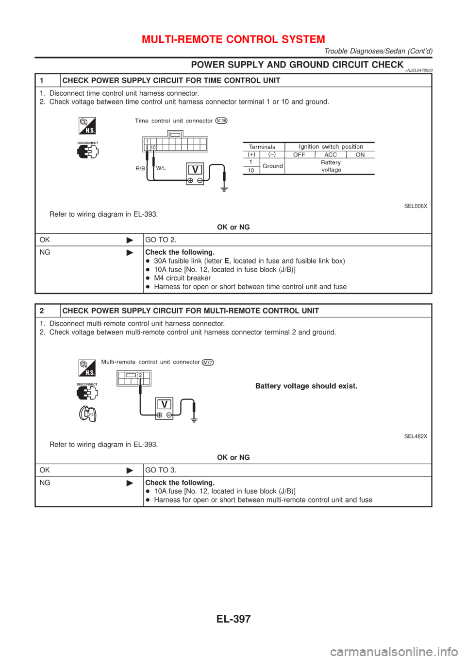
1 CHECK POWER SUPPLY CIRCUIT FOR TIME CONTROL UNIT
1. Disconnect time control unit harness connector.
2. Check voltage between time control unit harness connector terminal 1 or 10 and ground.
SEL006X
Refer to wiring diagram in EL-393.
OK or NG
OK©GO TO 2.
NG©Check the following.
+30A fusible link (letterE, located in fuse and fusible link box)
+10A fuse [No. 12, located in fuse block (J/B)]
+M4 circuit breaker
+Harness for open or short between time control unit and fuse
2 CHECK POWER SUPPLY CIRCUIT FOR MULTI-REMOTE CONTROL UNIT
1. Disconnect multi-remote control unit harness connector.
2. Check voltage between multi-remote control unit harness connector terminal 2 and ground.
SEL482X
Refer to wiring diagram in EL-393.
OK or NG
OK©GO TO 3.
NG©Check the following.
+10A fuse [No. 12, located in fuse block (J/B)]
+Harness for open or short between multi-remote control unit and fuse
MULTI-REMOTE CONTROL SYSTEM
Trouble Diagnoses/Sedan (Cont'd)
EL-397
Page 2359 of 2898

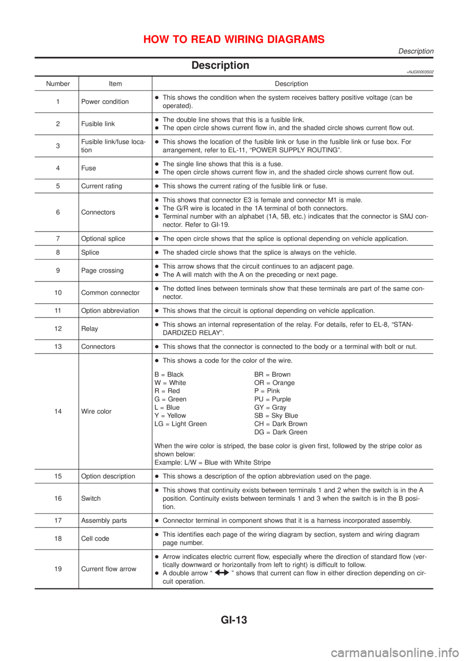
Description=NJGI0003S02
Number Item Description
1 Power condition+This shows the condition when the system receives battery positive voltage (can be
operated).
2 Fusible link+The double line shows that this is a fusible link.
+The open circle shows current flow in, and the shaded circle shows current flow out.
3Fusible link/fuse loca-
tion+This shows the location of the fusible link or fuse in the fusible link or fuse box. For
arrangement, refer to EL-11, ªPOWER SUPPLY ROUTINGº.
4 Fuse+The single line shows that this is a fuse.
+The open circle shows current flow in, and the shaded circle shows current flow out.
5 Current rating+This shows the current rating of the fusible link or fuse.
6 Connectors+This shows that connector E3 is female and connector M1 is male.
+The G/R wire is located in the 1A terminal of both connectors.
+Terminal number with an alphabet (1A, 5B, etc.) indicates that the connector is SMJ con-
nector. Refer to GI-19.
7 Optional splice+The open circle shows that the splice is optional depending on vehicle application.
8 Splice+The shaded circle shows that the splice is always on the vehicle.
9 Page crossing+This arrow shows that the circuit continues to an adjacent page.
+The A will match with the A on the preceding or next page.
10 Common connector+The dotted lines between terminals show that these terminals are part of the same con-
nector.
11 Option abbreviation+This shows that the circuit is optional depending on vehicle application.
12 Relay+This shows an internal representation of the relay. For details, refer to EL-8, ªSTAN-
DARDIZED RELAYº.
13 Connectors+This shows that the connector is connected to the body or a terminal with bolt or nut.
14 Wire color+This shows a code for the color of the wire.
B = Black
W = White
R = Red
G = Green
L = Blue
Y = Yellow
LG = Light GreenBR = Brown
OR = Orange
P = Pink
PU = Purple
GY = Gray
SB = Sky Blue
CH = Dark Brown
DG = Dark Green
When the wire color is striped, the base color is given first, followed by the stripe color as
shown below:
Example: L/W = Blue with White Stripe
15 Option description+This shows a description of the option abbreviation used on the page.
16 Switch+This shows that continuity exists between terminals 1 and 2 when the switch is in the A
position. Continuity exists between terminals 1 and 3 when the switch is in the B posi-
tion.
17 Assembly parts+Connector terminal in component shows that it is a harness incorporated assembly.
18 Cell code+This identifies each page of the wiring diagram by section, system and wiring diagram
page number.
19 Current flow arrow+Arrow indicates electric current flow, especially where the direction of standard flow (ver-
tically downward or horizontally from left to right) is difficult to follow.
+A double arrow ª
º shows that current can flow in either direction depending on cir-
cuit operation.
HOW TO READ WIRING DIAGRAMS
Description
GI-13
Page 2360 of 2898

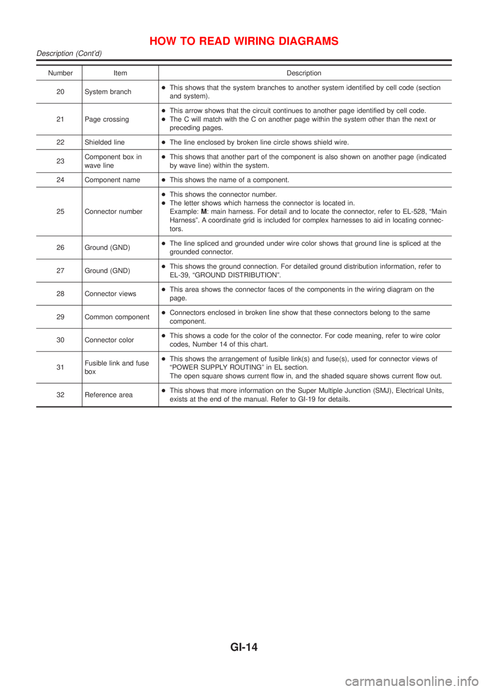
Number Item Description
20 System branch+This shows that the system branches to another system identified by cell code (section
and system).
21 Page crossing+This arrow shows that the circuit continues to another page identified by cell code.
+The C will match with the C on another page within the system other than the next or
preceding pages.
22 Shielded line+The line enclosed by broken line circle shows shield wire.
23Component box in
wave line+This shows that another part of the component is also shown on another page (indicated
by wave line) within the system.
24 Component name+This shows the name of a component.
25 Connector number+This shows the connector number.
+The letter shows which harness the connector is located in.
Example:M: main harness. For detail and to locate the connector, refer to EL-528, ªMain
Harnessº. A coordinate grid is included for complex harnesses to aid in locating connec-
tors.
26 Ground (GND)+The line spliced and grounded under wire color shows that ground line is spliced at the
grounded connector.
27 Ground (GND)+This shows the ground connection. For detailed ground distribution information, refer to
EL-39, ªGROUND DISTRIBUTIONº.
28 Connector views+This area shows the connector faces of the components in the wiring diagram on the
page.
29 Common component+Connectors enclosed in broken line show that these connectors belong to the same
component.
30 Connector color+This shows a code for the color of the connector. For code meaning, refer to wire color
codes, Number 14 of this chart.
31Fusible link and fuse
box+This shows the arrangement of fusible link(s) and fuse(s), used for connector views of
ªPOWER SUPPLY ROUTINGº in EL section.
The open square shows current flow in, and the shaded square shows current flow out.
32 Reference area+This shows that more information on the Super Multiple Junction (SMJ), Electrical Units,
exists at the end of the manual. Refer to GI-19 for details.
HOW TO READ WIRING DIAGRAMS
Description (Cont'd)
GI-14
Page 2366 of 2898

manual.
Fuse block Ð Junction box (J/B)
Fuse block Ð Junction box (J/B) connector number is shown in the
Reference Area of the wiring diagram. For connector terminal and
fuse arrangement, refer to the ªFUSE BLOCK Ð Junction Box
(J/B)º electrical reference page at the end of the manual.
Fuse and fusible link box
For fuse arrangement in the fuse and fusible link box, refer to the
ªFUSE AND FUSIBLE LINK BOXº electrical reference page at the
end of the manual.
Electrical units
Electrical unit connector symbols are shown in the Connector Area
of the wiring diagram.
However, when there is not enough space to show the connector
terminal arrangement in the Connector Area of the wiring diagram,
the electrical unit connector number is shown in the Reference
Area of the wiring diagram. For electrical unit connector terminal
arrangement, refer to the ªELECTRICAL UNITSº electrical refer-
ence page at the end of the manual. Most of the electrical unit
connectors on this page are shown from the harness side of the
connector.
Joint connector
Joint connector symbols are shown in the connector area of the
wiring diagram. For connector internal wiring layout and joint con-
nector terminal arrangement, refer to the ªJOINT CONNECTOR
(J/C)º electrical reference page at the end of the manual.
HOW TO READ WIRING DIAGRAMS
Description (Cont'd)
GI-20