2001 NISSAN ALMERA differential
[x] Cancel search: differentialPage 5 of 2898

Component Inspection .............................................251
DTC P0755 SHIFT SOLENOID VALVE B..................252
Description ...............................................................252
Wiring Diagram - AT - SSV/B ..................................254
Diagnostic Procedure ..............................................255
Component Inspection .............................................257
DTC P1705 THROTTLE POSITION SENSOR...........258
Description ...............................................................258
Wiring Diagram - AT - TPS ......................................261
Diagnostic Procedure ..............................................263
Component Inspection .............................................267
DTC P1760 OVERRUN CLUTCH SOLENOID
VALVE..........................................................................268
Description ...............................................................268
Wiring Diagram - AT - OVRCSV..............................270
Diagnostic Procedure ..............................................271
Component Inspection .............................................273
DTC BATT/FLUID TEMP SEN (A/T FLUID TEMP
SENSOR CIRCUIT AND TCM POWER SOURCE)....274
Description ...............................................................274
Wiring Diagram - AT - BA/FTS ................................276
Diagnostic Procedure ..............................................277
Component Inspection .............................................280
DTC VHCL SPEED SEN.MTR VEHICLE SPEED
SENSOR.MTR..............................................................281
Description ...............................................................281
Wiring Diagram - AT - VSSMTR ..............................283
Diagnostic Procedure ..............................................285
DTC CONTROL UNIT (RAM), CONTROL UNIT
(ROM)...........................................................................286
Description ...............................................................286
Diagnostic Procedure ..............................................286
DTC CONTROL UNIT (EEP ROM).............................288
Description ...............................................................288
Diagnostic Procedure ..............................................289
TROUBLE DIAGNOSES FOR SYMPTOMS...............290
Wiring Diagram - AT - NONDTC/General and
Except for Euro-OBD ...............................................290
Wiring Diagram - AT - NONDTC/EURO-OBD .........292
1. O/D OFF Indicator Lamp Does Not Come On....296
2. Engine Cannot Be Started In²P²and²N²
Position ....................................................................299
3. In²P²Position, Vehicle Moves Forward Or
Backward When Pushed .........................................300
4. In²N²Position, Vehicle Moves ...........................301
5. Large Shock.²N²->²R²Position .......................303
6. Vehicle Does Not Creep Backward In²R²
Position ....................................................................305
7. Vehicle Does Not Creep Forward In²D²,²2²
Or²1²Position .........................................................3088. Vehicle Cannot Be Started From D
1................... 311
9. A/T Does Not Shift: D
1-> D2Or Does Not
Kickdown: D
4-> D2..................................................314
10. A/T Does Not Shift: D
2-> D3.............................317
11. A/T Does Not Shift: D
3-> D4.............................320
12. A/T Does Not Perform Lock-up .........................323
13. A/T Does Not Hold Lock-up Condition ..............325
14. Lock-up Is Not Released ...................................327
15. Engine Speed Does Not Return To Idle (Light
Braking D
4-> D3).....................................................328
16. Vehicle Does Not Start From D
1.......................330
17. A/T Does Not Shift: D
4-> D3, When
Overdrive Control Switch²ON²->²OFF²...............331
18. A/T Does Not Shift: D
3-> 22, When Selector
Lever²D²->²2²Position.........................................332
19. A/T Does Not Shift: 2
2-> 11, When Selector
Lever²2²->²1²Position .........................................333
20. Vehicle Does Not Decelerate By Engine
Brake........................................................................334
21. TCM Self-diagnosis Does Not Activate (PNP,
Overdrive Control and Throttle Position Switches
Circuit Checks) ........................................................334
A/T SHIFT LOCK SYSTEM.........................................343
Description ...............................................................343
Shift Lock System Electrical Parts Location............343
Wiring Diagram - SHIFT -........................................344
Diagnostic Procedure ..............................................345
KEY INTERLOCK CABLE..........................................349
Components.............................................................349
Removal ...................................................................349
Installation ................................................................350
ON-VEHICLE SERVICE..............................................351
Control Valve Assembly and Accumulators .............351
Control Cable Adjustment ........................................352
Park/Neutral Position (PNP) Switch Adjustment .....352
Differential Side Oil Seal Replacement ...................353
Revolution Sensor Replacement .............................353
REMOVAL AND INSTALLATION...............................354
Removal ...................................................................354
Installation ................................................................355
OVERHAUL.................................................................357
Components-1 3AX00, 3AX01, 3AX19, 3AX63
and 3AX64 models ..................................................357
Components-1 3AX10 and 3AX18 models .............358
Components-2 3AX00, 3AX01, 3AX19, 3AX63
and 3AX64 models ..................................................359
Components-2 3AX10 and 3AX18 models .............360
Components-3 3AX00, 3AX01, 3AX19, 3AX63
and 3AX64 models ..................................................361
Components-3 3AX10 and 3AX18 models .............362
Oil Channel ..............................................................363
CONTENTS(Cont'd)
AT-3
Page 13 of 2898
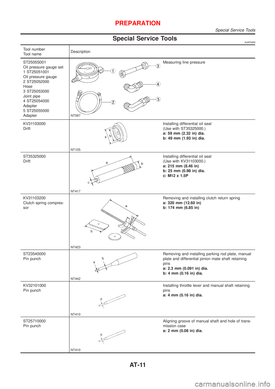
Special Service ToolsNJAT0006
Tool number
Tool nameDescription
ST2505S001
Oil pressure gauge set
1 ST25051001
Oil pressure gauge
2 ST25052000
Hose
3 ST25053000
Joint pipe
4 ST25054000
Adapter
5 ST25055000
Adapter
NT097
Measuring line pressure
KV31103000
Drift
NT105
Installing differential oil seal
(Use with ST35325000.)
a: 59 mm (2.32 in) dia.
b: 49 mm (1.93 in) dia.
ST35325000
Drift
NT417
Installing differential oil seal
(Use with KV31103000.)
a: 215 mm (8.46 in)
b: 25 mm (0.98 in) dia.
c: M12 x 1.5P
KV31103200
Clutch spring compres-
sor
NT423
Removing and installing clutch return spring
a: 320 mm (12.60 in)
b: 174 mm (6.85 in)
ST23540000
Pin punch
NT442
Removing and installing parking rod plate, manual
plate and differential pinion mate shaft retaining
pins
a: 2.3 mm (0.091 in) dia.
b: 4 mm (0.16 in) dia.
KV32101000
Pin punch
NT410
Installing throttle lever and manual shaft retaining
pins
a: 4 mm (0.16 in) dia.
ST25710000
Pin punch
NT410
Aligning groove of manual shaft and hole of trans-
mission case
a: 2 mm (0.08 in) dia.
PREPARATION
Special Service Tools
AT-11
Page 14 of 2898
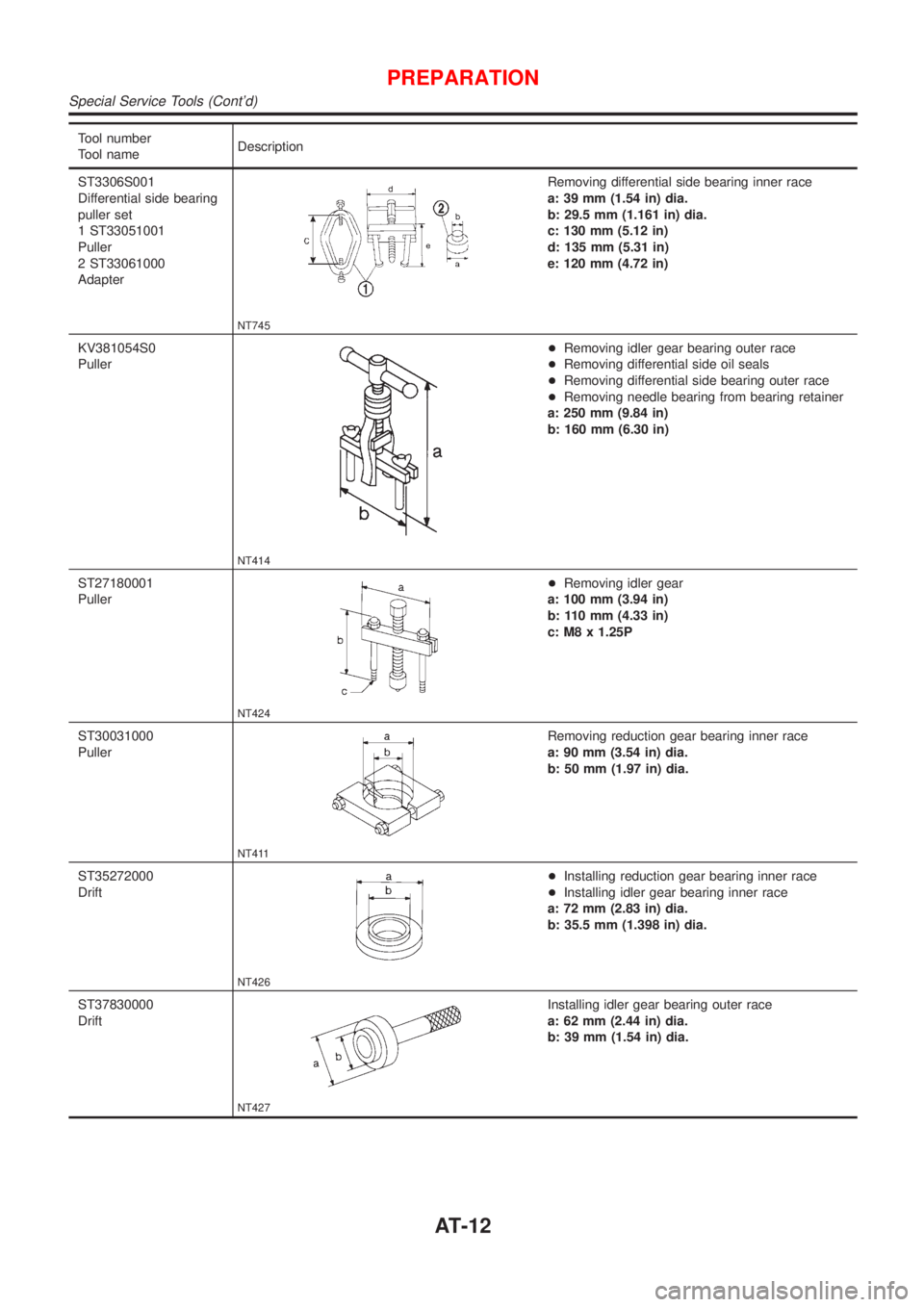
Tool number
Tool nameDescription
ST3306S001
Differential side bearing
puller set
1 ST33051001
Puller
2 ST33061000
Adapter
NT745
Removing differential side bearing inner race
a: 39 mm (1.54 in) dia.
b: 29.5 mm (1.161 in) dia.
c: 130 mm (5.12 in)
d: 135 mm (5.31 in)
e: 120 mm (4.72 in)
KV381054S0
Puller
NT414
+Removing idler gear bearing outer race
+Removing differential side oil seals
+Removing differential side bearing outer race
+Removing needle bearing from bearing retainer
a: 250 mm (9.84 in)
b: 160 mm (6.30 in)
ST27180001
Puller
NT424
+Removing idler gear
a: 100 mm (3.94 in)
b: 110 mm (4.33 in)
c: M8 x 1.25P
ST30031000
Puller
NT411
Removing reduction gear bearing inner race
a: 90 mm (3.54 in) dia.
b: 50 mm (1.97 in) dia.
ST35272000
Drift
NT426
+Installing reduction gear bearing inner race
+Installing idler gear bearing inner race
a: 72 mm (2.83 in) dia.
b: 35.5 mm (1.398 in) dia.
ST37830000
Drift
NT427
Installing idler gear bearing outer race
a: 62 mm (2.44 in) dia.
b: 39 mm (1.54 in) dia.
PREPARATION
Special Service Tools (Cont'd)
AT-12
Page 15 of 2898
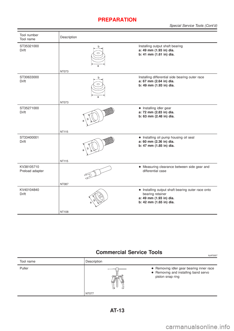
Tool number
Tool nameDescription
ST35321000
Drift
NT073
Installing output shaft bearing
a: 49 mm (1.93 in) dia.
b: 41 mm (1.61 in) dia.
ST30633000
Drift
NT073
Installing differential side bearing outer race
a: 67 mm (2.64 in) dia.
b: 49 mm (1.93 in) dia.
ST35271000
Drift
NT115
+Installing idler gear
a: 72 mm (2.83 in) dia.
b: 63 mm (2.48 in) dia.
ST33400001
Drift
NT115
+Installing oil pump housing oil seal
a: 60 mm (2.36 in) dia.
b: 47 mm (1.85 in) dia.
KV38105710
Preload adapter
NT087
+Measuring clearance between side gear and
differential case
KV40104840
Drift
NT108
+Installing output shaft bearing outer race onto
bearing retainer
a: 49 mm (1.93 in) dia.
b: 42 mm (1.65 in) dia.
Commercial Service ToolsNJAT0007
Tool name Description
Puller
NT077
+Removing idler gear bearing inner race
+Removing and installing band servo
piston snap ring
PREPARATION
Special Service Tools (Cont'd)
AT-13
Page 16 of 2898
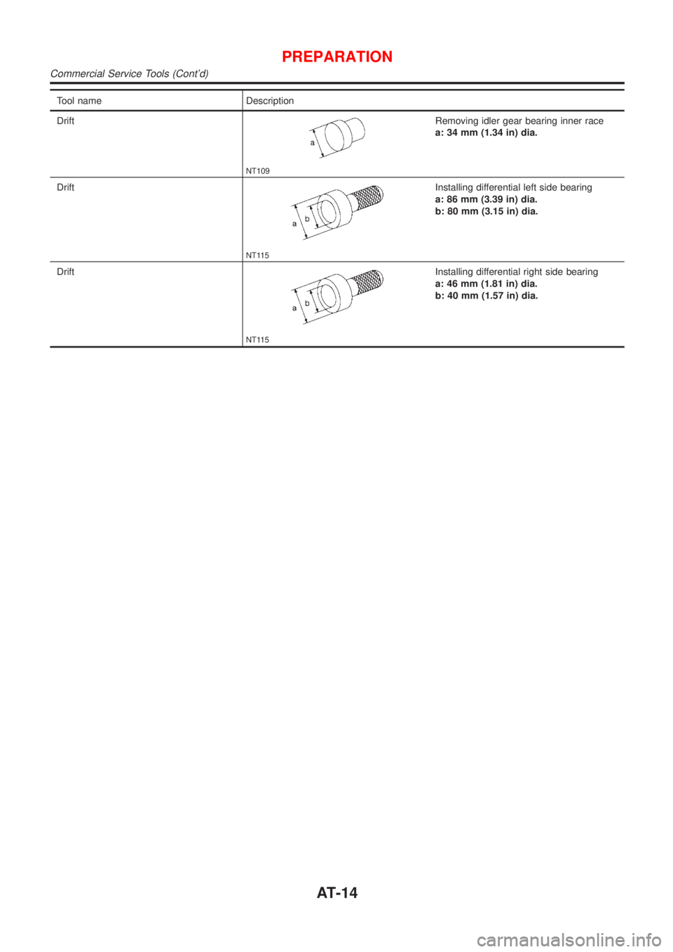
Tool name Description
Drift
NT109
Removing idler gear bearing inner race
a: 34 mm (1.34 in) dia.
Drift
NT115
Installing differential left side bearing
a: 86 mm (3.39 in) dia.
b: 80 mm (3.15 in) dia.
Drift
NT115
Installing differential right side bearing
a: 46 mm (1.81 in) dia.
b: 40 mm (1.57 in) dia.
PREPARATION
Commercial Service Tools (Cont'd)
AT-14
Page 355 of 2898
SAT480J
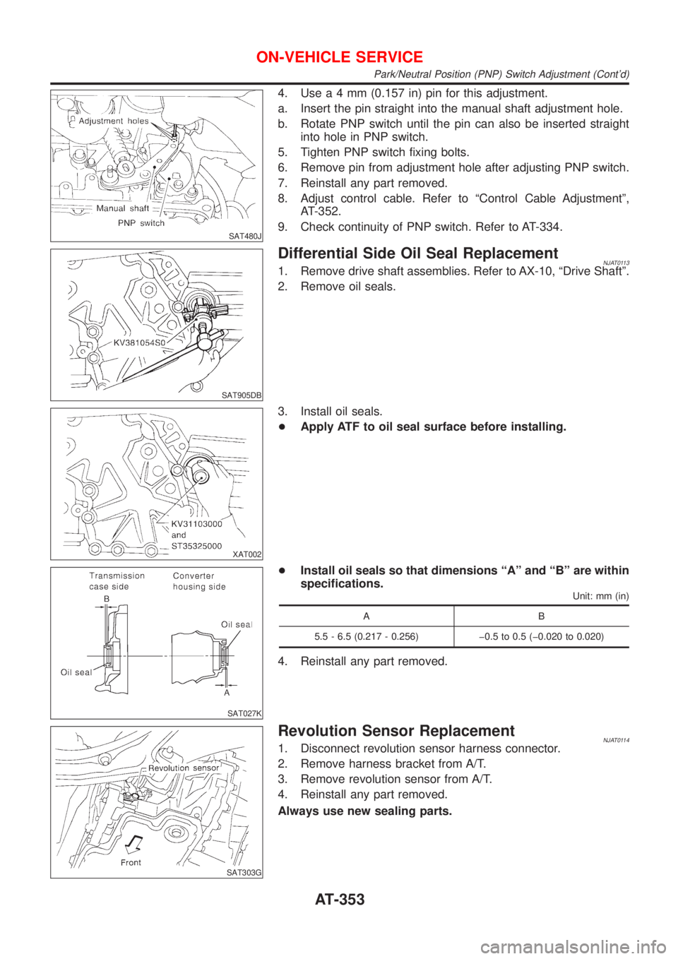
4. Usea4mm(0.157 in) pin for this adjustment.
a. Insert the pin straight into the manual shaft adjustment hole.
b. Rotate PNP switch until the pin can also be inserted straight
into hole in PNP switch.
5. Tighten PNP switch fixing bolts.
6. Remove pin from adjustment hole after adjusting PNP switch.
7. Reinstall any part removed.
8. Adjust control cable. Refer to ªControl Cable Adjustmentº,
AT-352.
9. Check continuity of PNP switch. Refer to AT-334.
SAT905DB
Differential Side Oil Seal ReplacementNJAT01131. Remove drive shaft assemblies. Refer to AX-10, ªDrive Shaftº.
2. Remove oil seals.
XAT002
3. Install oil seals.
+Apply ATF to oil seal surface before installing.
SAT027K
+Install oil seals so that dimensions ªAº and ªBº are within
specifications.
Unit: mm (in)
AB
5.5 - 6.5 (0.217 - 0.256) þ0.5 to 0.5 (þ0.020 to 0.020)
4. Reinstall any part removed.
SAT303G
Revolution Sensor ReplacementNJAT01141. Disconnect revolution sensor harness connector.
2. Remove harness bracket from A/T.
3. Remove revolution sensor from A/T.
4. Reinstall any part removed.
Always use new sealing parts.
ON-VEHICLE SERVICE
Park/Neutral Position (PNP) Switch Adjustment (Cont'd)
AT-353
Page 371 of 2898
SAT023DA
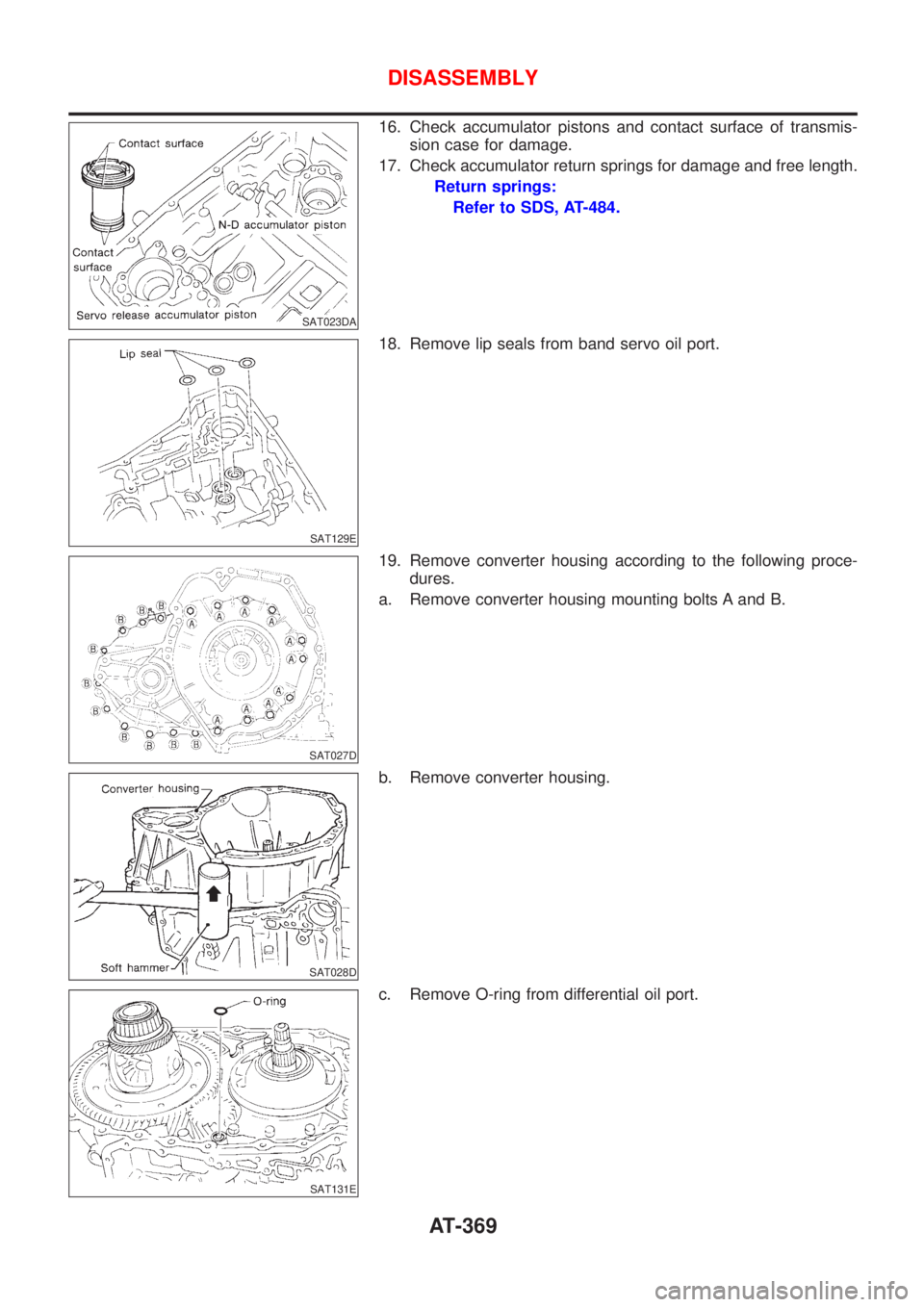
16. Check accumulator pistons and contact surface of transmis-
sion case for damage.
17. Check accumulator return springs for damage and free length.
Return springs:
Refer to SDS, AT-484.
SAT129E
18. Remove lip seals from band servo oil port.
SAT027D
19. Remove converter housing according to the following proce-
dures.
a. Remove converter housing mounting bolts A and B.
SAT028D
b. Remove converter housing.
SAT131E
c. Remove O-ring from differential oil port.
DISASSEMBLY
AT-369
Page 372 of 2898
SAT030D
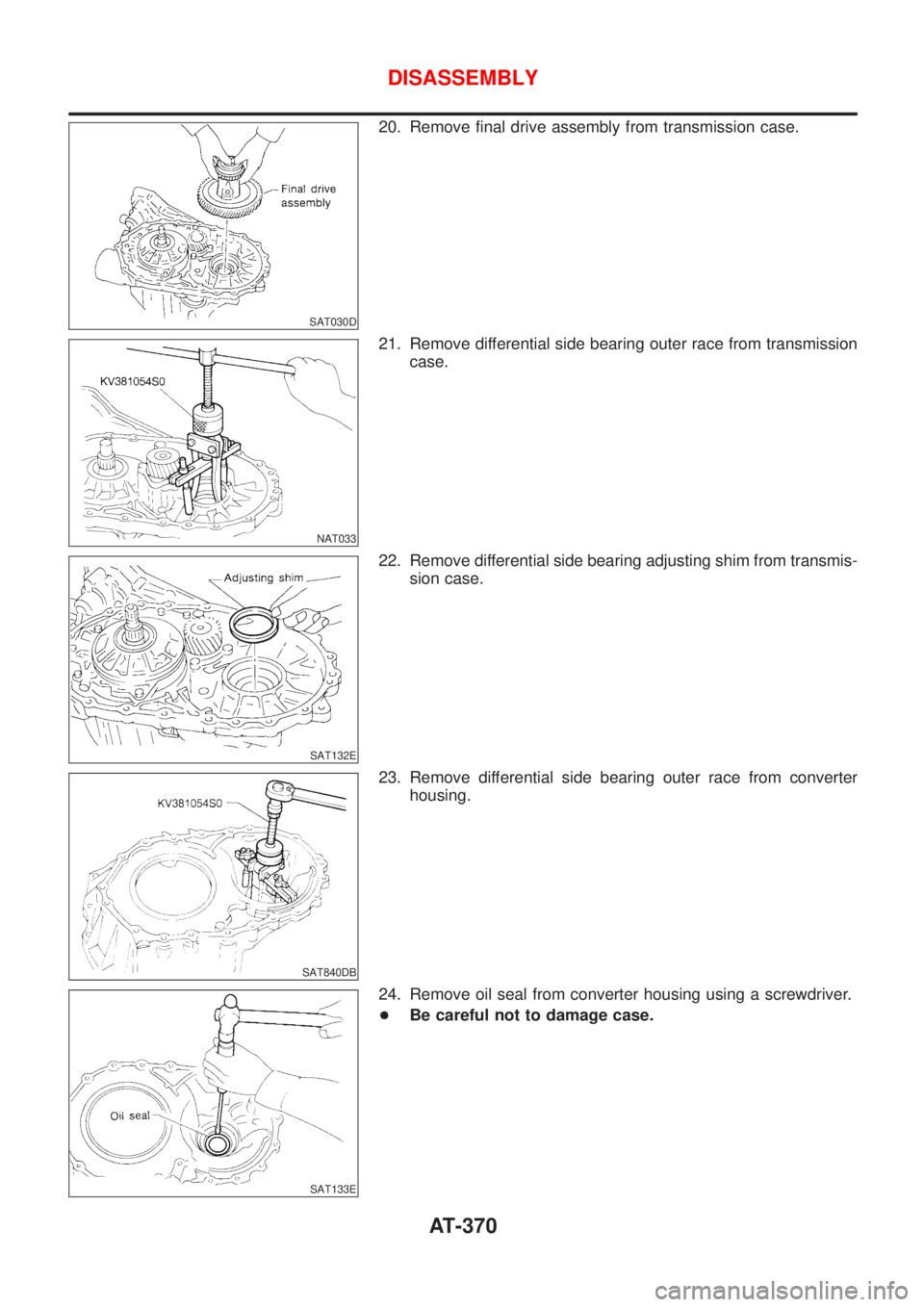
20. Remove final drive assembly from transmission case.
NAT033
21. Remove differential side bearing outer race from transmission
case.
SAT132E
22. Remove differential side bearing adjusting shim from transmis-
sion case.
SAT840DB
23. Remove differential side bearing outer race from converter
housing.
SAT133E
24. Remove oil seal from converter housing using a screwdriver.
+Be careful not to damage case.
DISASSEMBLY
AT-370