Page 456 of 2898

SAT874DA
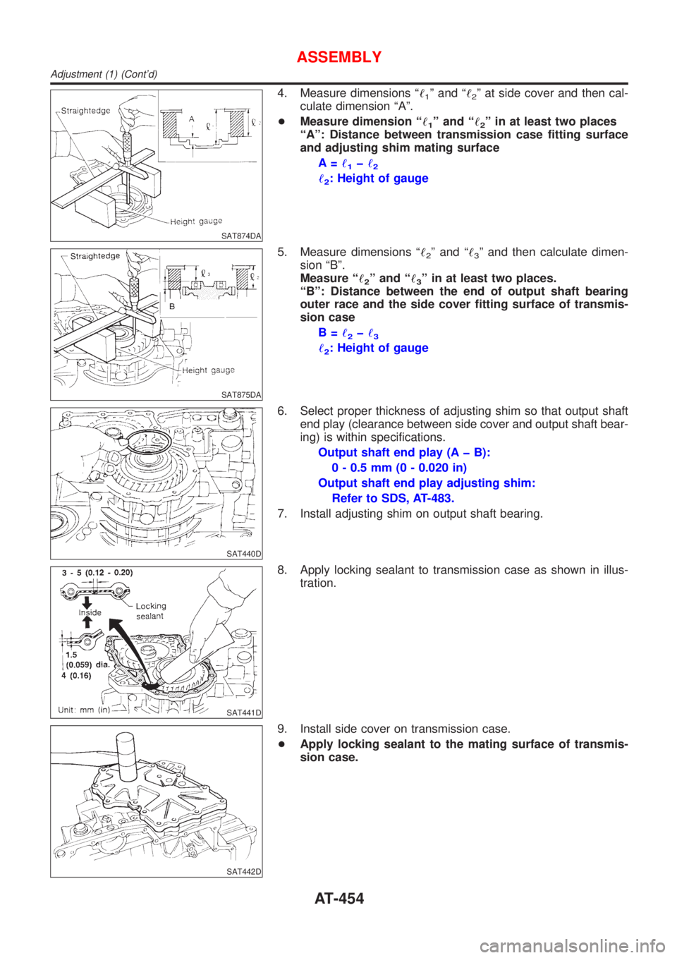
4. Measure dimensions ª!1º and ª!2º at side cover and then cal-
culate dimension ªAº.
+Measure dimension ª!
1º and ª!2º in at least two places
ªAº: Distance between transmission case fitting surface
and adjusting shim mating surface
A=!
1þ!2
!2: Height of gauge
SAT875DA
5. Measure dimensions ª!2º and ª!3º and then calculate dimen-
sion ªBº.
Measure ª!
2º and ª!3º in at least two places.
ªBº: Distance between the end of output shaft bearing
outer race and the side cover fitting surface of transmis-
sion case
B=!
2þ!3
!2: Height of gauge
SAT440D
6. Select proper thickness of adjusting shim so that output shaft
end play (clearance between side cover and output shaft bear-
ing) is within specifications.
Output shaft end play (A þ B):
0 - 0.5 mm (0 - 0.020 in)
Output shaft end play adjusting shim:
Refer to SDS, AT-483.
7. Install adjusting shim on output shaft bearing.
SAT441D
8. Apply locking sealant to transmission case as shown in illus-
tration.
SAT442D
9. Install side cover on transmission case.
+Apply locking sealant to the mating surface of transmis-
sion case.
ASSEMBLY
Adjustment (1) (Cont'd)
AT-454
Page 513 of 2898
SRA711A
1. Remove brake caliper assembly.
2. Remove wheel bearing lock nut.
3. Remove brake rotor (models with disk brake) or brake drum
(models with drum brakes).
4. Remove wheel hub bearing from spindle.
CAUTION:
Do not disconnect brake hose from caliper.
+Suspend caliper assembly with wire so as not to stretch
brake hose.
+Be careful not to depress brake pedal, or piston will pop
out.
Make sure brake hose is not twisted.
ARA082
5. Remove the sensor rotor using suitable puller, drift and bea
ring replacer.
SAX014
INSTALLATIONNJAX0030+With vehicles equipped with ABS, press-fit ABS sensor rotor
into wheel hub bearing using a drift.
Do not reuse ABS sensor rotor. When installing, replace it
with a new one.
SRA734AB
+Press-fit ABS sensor rotor as far as the location shown in fig-
ure at left.
Height ªhº:
Models with disk brakes
1.5 - 2.5 mm (0.059 - 0.098 in)
Models with drum brakes
17.7 - 18.7 mm (0.697 - 0.736 in)
REAR AXLE
Wheel Hub (Cont'd)
AX-25
Page 528 of 2898
Removal and InstallationNJBR0015
JBR752E
SBR997
InspectionNJBR0016Check brake pedal for following items.
+Brake pedal bend
+Clevis pin deformation
+Crack of any welded portion
+Crack or deformation of clevis pin stopper
SBR657EA
AdjustmentNJBR0017Check brake pedal free height from metal panel. Adjust if neces-
sary.
H: Free height
Refer to SDS, BR-101.
C
1,C2: Clearance between pedal stopper and threaded
end of stop lamp switch and brake switch
0.74 - 1.96 mm (0.0291 - 0.0772 in)
D: Depressed height
LHD (M/T): More than 90 mm (3.54 in)
LHD (A/T): More than 95 mm (3.74 in)
RHD (M/T): More than 90 mm (3.54 in)
RHD (A/T): More than 95 mm (3.74 in)
Under force of 490 N (50 kg, 110 lb) with engine run-
ning
A: Pedal free play at pedal pad
1.0 - 3.0 mm (0.039 - 0.118 in)
BRAKE PEDAL AND BRACKET
Removal and Installation
BR-12
Page 529 of 2898
SBR229E
1. Loosen lock nut and adjust pedal free height by turning brake
booster input rod. Then tighten lock nut.
2. Check pedal free play.
Make sure that stop lamps go off when pedal is released.
3. Check brake pedal's depressed height while engine is running.
If lower than specification, check brake system for leaks, accu-
mulation of air or any damage to components (master cylinder,
wheel cylinder, etc.); then make necessary repairs.
BRAKE PEDAL AND BRACKET
Adjustment (Cont'd)
BR-13
Page 617 of 2898

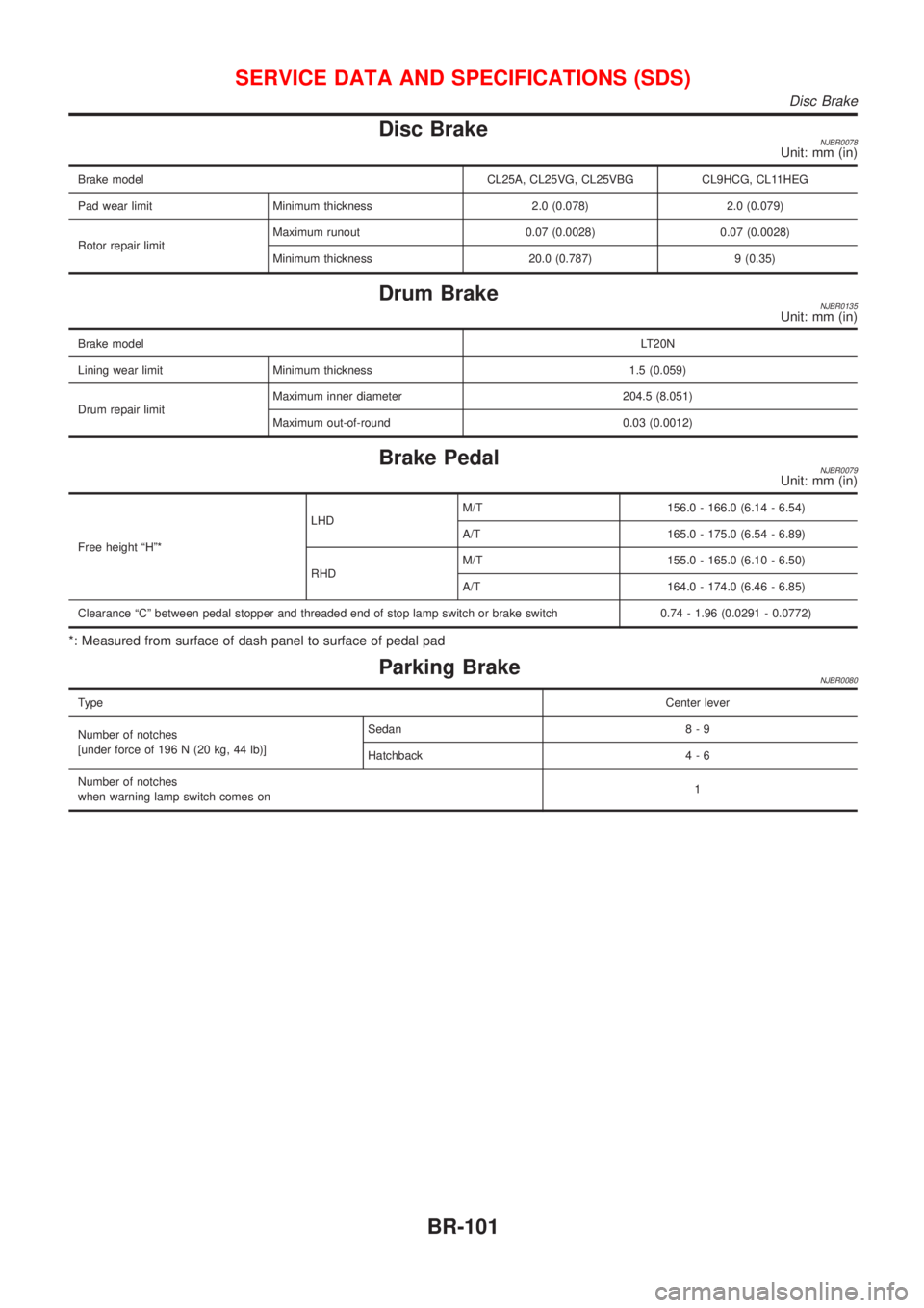
Disc BrakeNJBR0078Unit: mm (in)
Brake model CL25A, CL25VG, CL25VBG CL9HCG, CL11HEG
Pad wear limit Minimum thickness 2.0 (0.078) 2.0 (0.079)
Rotor repair limitMaximum runout 0.07 (0.0028) 0.07 (0.0028)
Minimum thickness 20.0 (0.787) 9 (0.35)
Drum BrakeNJBR0135Unit: mm (in)
Brake modelLT20N
Lining wear limit Minimum thickness 1.5 (0.059)
Drum repair limitMaximum inner diameter 204.5 (8.051)
Maximum out-of-round 0.03 (0.0012)
Brake PedalNJBR0079Unit: mm (in)
Free height ªHº*LHDM/T 156.0 - 166.0 (6.14 - 6.54)
A/T 165.0 - 175.0 (6.54 - 6.89)
RHDM/T 155.0 - 165.0 (6.10 - 6.50)
A/T 164.0 - 174.0 (6.46 - 6.85)
Clearance ªCº between pedal stopper and threaded end of stop lamp switch or brake switch 0.74 - 1.96 (0.0291 - 0.0772)
*: Measured from surface of dash panel to surface of pedal pad
Parking BrakeNJBR0080
TypeCenter lever
Number of notches
[under force of 196 N (20 kg, 44 lb)]Sedan 8 - 9
Hatchback 4 - 6
Number of notches
when warning lamp switch comes on1
SERVICE DATA AND SPECIFICATIONS (SDS)
Disc Brake
BR-101
Page 686 of 2898
ADJUSTMENTNJBT0022S03
SBT004A
If any height difference between glass lid and roof is found, check
glass lid fit and adjust as follows:
Height Difference AdjustmentNJBT0022S03021. Tilt glass lid up and down.
2. Check height difference between roof panel and glass lid to
see if it is as ªA-Aº as shown in the figure above.
3. If necessary, adjust it by using one of following procedures.
+Adjust by adding or removing adjustment shim(s) between
glass lid and link assembly.
+If glass lid protrudes above roof panel, add shim(s) or plain
washer(s) at sunroof mounting bracket or stud bolt locations to
adjust sunroof installation as required.
SUNROOF
Trouble Diagnoses (Cont'd)
BT-68
Page 723 of 2898

SCL466-C
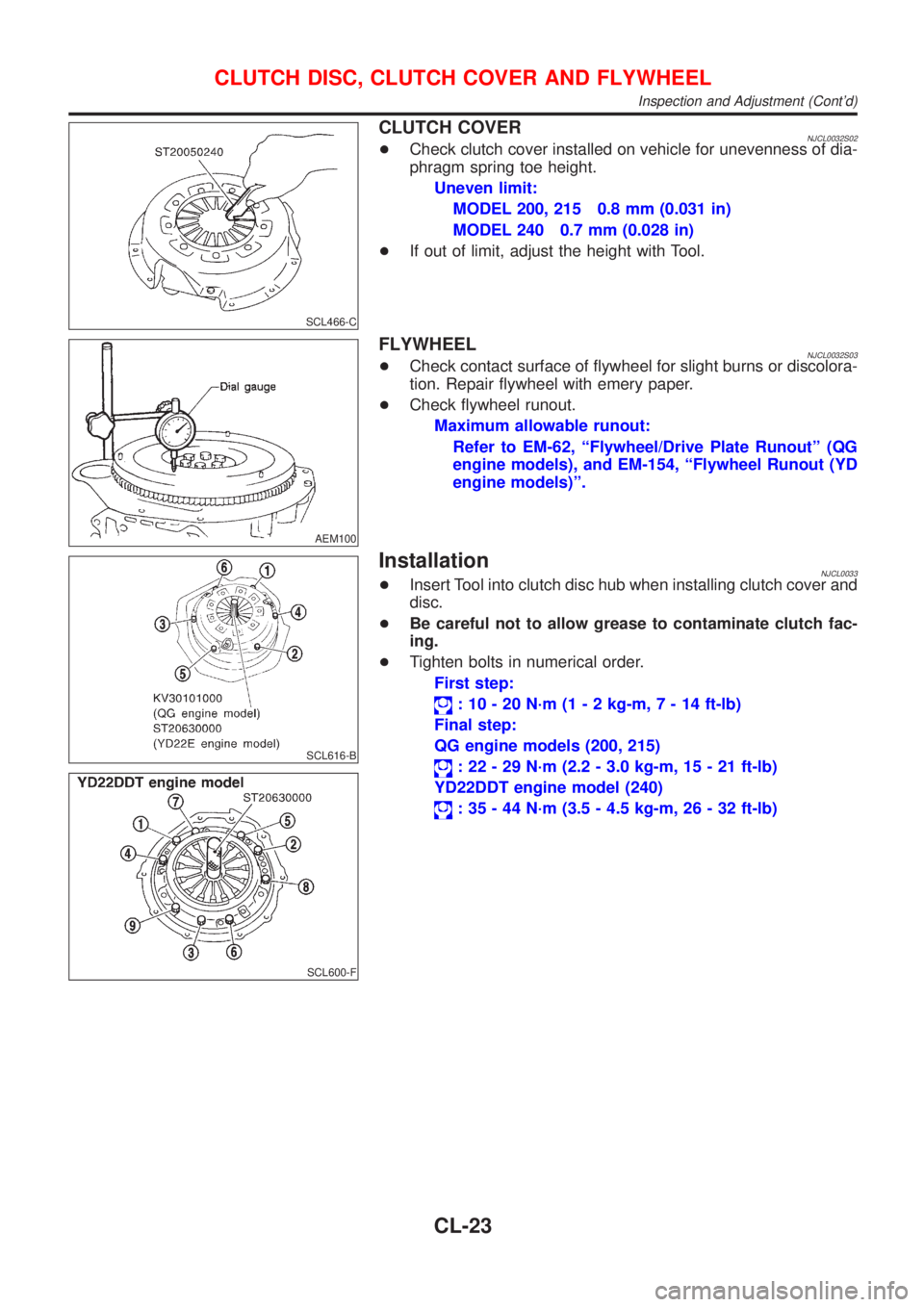
CLUTCH COVERNJCL0032S02+Check clutch cover installed on vehicle for unevenness of dia-
phragm spring toe height.
Uneven limit:
MODEL 200, 215 0.8 mm (0.031 in)
MODEL 240 0.7 mm (0.028 in)
+If out of limit, adjust the height with Tool.
AEM100
FLYWHEELNJCL0032S03+Check contact surface of flywheel for slight burns or discolora-
tion. Repair flywheel with emery paper.
+Check flywheel runout.
Maximum allowable runout:
Refer to EM-62, ªFlywheel/Drive Plate Runoutº (QG
engine models), and EM-154, ªFlywheel Runout (YD
engine models)º.
SCL616-B
SCL600-F
InstallationNJCL0033+Insert Tool into clutch disc hub when installing clutch cover and
disc.
+Be careful not to allow grease to contaminate clutch fac-
ing.
+Tighten bolts in numerical order.
First step:
: 10 - 20 N´m (1 - 2 kg-m,7-14ft-lb)
Final step:
QG engine models (200, 215)
: 22 - 29 N´m (2.2 - 3.0 kg-m, 15 - 21 ft-lb)
YD22DDT engine model (240)
: 35 - 44 N´m (3.5 - 4.5 kg-m, 26 - 32 ft-lb)
CLUTCH DISC, CLUTCH COVER AND FLYWHEEL
Inspection and Adjustment (Cont'd)
CL-23
Page 724 of 2898

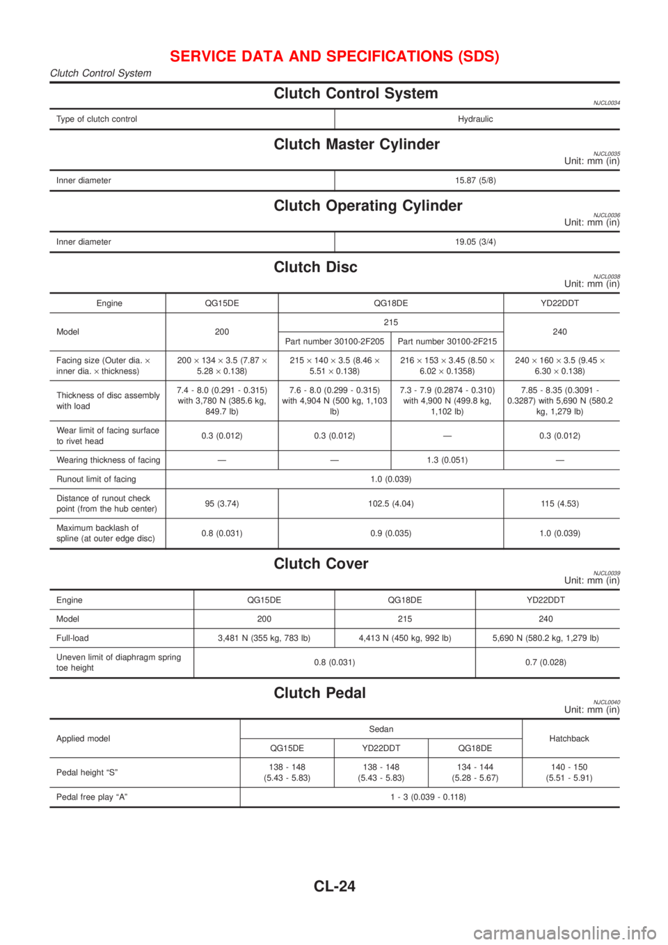
Clutch Control SystemNJCL0034
Type of clutch controlHydraulic
Clutch Master CylinderNJCL0035Unit: mm (in)
Inner diameter15.87 (5/8)
Clutch Operating CylinderNJCL0036Unit: mm (in)
Inner diameter19.05 (3/4)
Clutch DiscNJCL0038Unit: mm (in)
Engine QG15DE QG18DE YD22DDT
Model 200215
240
Part number 30100-2F205 Part number 30100-2F215
Facing size (Outer dia.´
inner dia.´thickness)200´134´3.5 (7.87´
5.28´0.138)215´140´3.5 (8.46´
5.51´0.138)216´153´3.45 (8.50´
6.02´0.1358)240´160´3.5 (9.45´
6.30´0.138)
Thickness of disc assembly
with load7.4 - 8.0 (0.291 - 0.315)
with 3,780 N (385.6 kg,
849.7 lb)7.6 - 8.0 (0.299 - 0.315)
with 4,904 N (500 kg, 1,103
lb)7.3 - 7.9 (0.2874 - 0.310)
with 4,900 N (499.8 kg,
1,102 lb)7.85 - 8.35 (0.3091 -
0.3287) with 5,690 N (580.2
kg, 1,279 lb)
Wear limit of facing surface
to rivet head0.3 (0.012) 0.3 (0.012) Ð 0.3 (0.012)
Wearing thickness of facing Ð Ð 1.3 (0.051) Ð
Runout limit of facing 1.0 (0.039)
Distance of runout check
point (from the hub center)95 (3.74) 102.5 (4.04) 115 (4.53)
Maximum backlash of
spline (at outer edge disc)0.8 (0.031) 0.9 (0.035) 1.0 (0.039)
Clutch CoverNJCL0039Unit: mm (in)
Engine QG15DE QG18DE YD22DDT
Model 200 215 240
Full-load 3,481 N (355 kg, 783 lb) 4,413 N (450 kg, 992 lb) 5,690 N (580.2 kg, 1,279 lb)
Uneven limit of diaphragm spring
toe height0.8 (0.031) 0.7 (0.028)
Clutch PedalNJCL0040Unit: mm (in)
Applied modelSedan
Hatchback
QG15DE YD22DDT QG18DE
Pedal height ªSº138 - 148
(5.43 - 5.83)138 - 148
(5.43 - 5.83)134 - 144
(5.28 - 5.67)140 - 150
(5.51 - 5.91)
Pedal free play ªAº1 - 3 (0.039 - 0.118)
SERVICE DATA AND SPECIFICATIONS (SDS)
Clutch Control System
CL-24