2001 NISSAN ALMERA trunk release
[x] Cancel search: trunk releasePage 2362 of 2898

AGI070
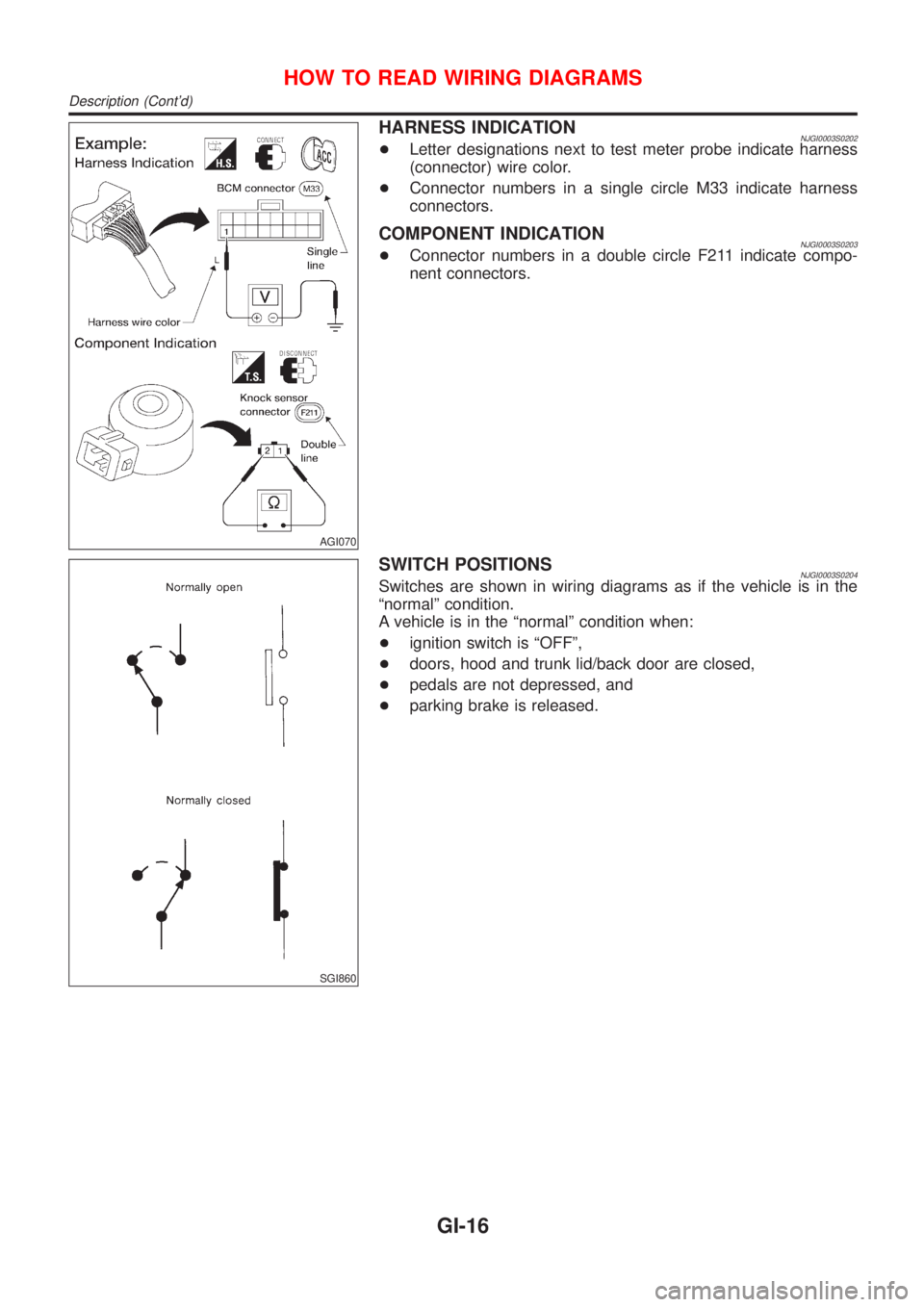
HARNESS INDICATIONNJGI0003S0202+Letter designations next to test meter probe indicate harness
(connector) wire color.
+Connector numbers in a single circle M33 indicate harness
connectors.
COMPONENT INDICATIONNJGI0003S0203+Connector numbers in a double circle F211 indicate compo-
nent connectors.
SGI860
SWITCH POSITIONSNJGI0003S0204Switches are shown in wiring diagrams as if the vehicle is in the
ªnormalº condition.
A vehicle is in the ªnormalº condition when:
+ignition switch is ªOFFº,
+doors, hood and trunk lid/back door are closed,
+pedals are not depressed, and
+parking brake is released.
HOW TO READ WIRING DIAGRAMS
Description (Cont'd)
GI-16
Page 2502 of 2898

Electronic fuel injection pump ........ EC-618, 716,
723, 757, 764, 771, 778, 785, 803
Engine compartment ................................. BT-78
Engine control circuit diagram .......... EC-25, 606
Engine control component parts
location .......................................... EC-21, 603
Engine control module (ECM) ....... EC-391, 659,
714, 792, 794, 799, 801
Engine control system diagram and
chart .............................................. EC-29, 608
Engine coolant temperature sensor
(ECTS) ........................................ EC-201, 680
Engine fail-safe system ........................... EC-154
Engine oil precautions .................................. GI-7
Engine outer component parts ................. EM-11
Engine removal ................................ EM-51, 137
Engine room - See Engine
compartment .......................................... BT-78
Engine serial number ................................. GI-41
Evaporative emission (EVAP)
system ................................................... EC-36
Exhaust gas recirculation (EGR)
valve .................................... EC-343, 425, 491
Exhaust system ................................... FE-15, 32
Exterior ...................................................... BT-47
F
F/PUMP - Wiring diagram ....................... EC-563
FR02 - Wiring diagram ... EC-219, 239, 247, 451
FR02/H - Wiring diagram ................ EC-254, 458
FUEL - Wiring diagram ................... EC-299, 307
Fan switch ................................................. HA-54
Final drive (FF A/T) .................................. AT-442
Final drive (FF M/T) .............. MT-44, 77, 93, 107
Finisher, interior - See Trim ....................... BT-31
Finisher, trunk lid ....................................... BT-45
Floor trim ................................................... BT-31
Fluid temperature sensor (A/T) ................ AT-194
Fluids ........................................................ MA-16
Flywheel (clutch) ....................................... CL-22
Flywheel runout ................................ EM-62, 154
Fog lamp, front, removal and
installation ................................................ BT-7
Fog lamp, front .......................................... EL-89
Fork rod (M/T) .............................. MT-32, 56, 94
Forward clutch ......................................... AT-412
Freeze frame data .............................. EC-61, 72
Front axle .................................................... AX-2
Front bumper ............................................... BT-7
Front combination lamp removal and
installation ................................................ BT-7
Front disc brake ........................................ BR-27
Front door .................................................. BT-16
Front fog lamp removal and
installation ................................................ BT-7
Front fog lamp ........................................... EL-89
Front heated oxygen sensor (HO2S)
heater .......................................... EC-252, 457Front heated oxygen sensor (HO2S) ..... EC-216,
224, 230, 236, 245, 450
Front seat belt ............................................. RS-5
Front seat .................................................. BT-56
Front suspension ........................................ SU-2
Front washer ............................................ EL-215
Front wiper ............................................... EL-215
Fuel cut control (at no load & high
engine speed) ............................... EC-36, 612
Fuel gauge ............................................... EL-144
Fuel injection system .............. EC-297, 305, 610
Fuel injector ............................................ EC-541
Fuel precautions ........................................... GI-8
Fuel pressure check ................................. EC-40
Fuel pressure regulator ............................. EC-41
Fuel pressure release ............................... EC-40
Fuel pump relay ...................................... EC-561
Fuel pump ............................................... EC-561
Fuel system ........................................... FE-5, 20
Fuel tank vacuum relief valve ................... EC-37
Fuse block ............................................... EL-577
Fuse ........................................................... EL-38
Fusible link ................................................. EL-38
G
GLOW - Wiring diagram ......................... EC-806
Garage jack and safety stand .................... GI-45
Gauges .................................................... EL-144
Gear components (M/T) ............... MT-31, 55, 93
Generator - See Alternator ....................... SC-31
Generic scan tool (GST) ........................... EC-94
Glass .......................................................... BT-17
Glow plug ................................................ EC-806
Glow relay ............................................... EC-806
Grease ...................................................... MA-16
Ground distribution .................................... EL-39
H
H/LAMP - Wiring diagram ................... EL-60, 61
HEATER - Wiring diagram ........................ HA-24
HFC134a (R134a) system
precaution ................................................ HA-2
HFC134a (R134a) system service
procedure .............................................. HA-78
HFC134a (R134a) system service
tools ....................................................... HA-11
HFC134a system service equipment
precaution ................................................ HA-6
HORN - Wiring diagram .................. EL-234, 235
HSEAT - Wiring diagram ................. EL-288, 290
Harness connector ...................................... EL-6
Harness layout ......................................... EL-522
Hazard warning lamp ................................ EL-96
Headlamp removal and installation ............. BT-7
Headlamp washer .................................... EL-231
Headlamp .................................................. EL-60
ALPHABETICAL INDEX
IDX-4
Page 2505 of 2898

Seat, rear ................................................... BT-60
Self-diagnostic results ....................... EC-74, 628
Shift control components (M/T) .... MT-32, 56, 94
Shift fork (M/T) .............................. MT-32, 56, 94
Shift lever .................................................. MT-29
Shift lock system ...................................... AT-343
Shift schedule .......................................... AT-470
Shift solenoid valve A (A/T) ..... AT-204, 209, 222
Shift solenoid valve B (A/T) ............. AT-204, 209
Shock absorber (front) .............................. SU-10
Shock absorber (rear) ............................... SU-21
Side air bag ........................................ RS-36, 38
Side trim .................................................... BT-31
Spare tire size ............................................ GI-43
Speedometer ........................................... EL-144
Spiral cable ............................................... RS-29
Spot lamp ................................................ EL-141
Spring (Wheelarch) height .......................... SU-6
Stabilizer bar (front) ................................... SU-11
Stall test (A/T) ............................................ AT-80
Standardized relay ....................................... EL-8
Start signal ...................................... EC-557, 823
Starter ....................................................... SC-18
Starting system ......................................... SC-13
Steering linkage ......................................... ST-16
Steering switch .......................................... EL-59
Steering wheel and column ....................... ST-11
Steering wheel play ..................................... ST-6
Steering wheel turning force ....................... ST-8
Stop lamp .................................................. EL-85
Striking rod (M/T) .......................... MT-32, 56, 94
Strut (front) .................................................. SU-9
Strut (rear) ................................................. SU-20
Sub-gear (M/T) ................................... MT-31, 55
Sunroof, electric ....................................... EL-292
Sunroof ...................................................... BT-63
Super lock ................................................ EL-349
Supplemental Restraint System ............... RS-20
Supplemental restraint system - Wiring
diagram .................................................. RS-53
Swirl control valve control solenoid
valve ............................................ EC-399, 475
Symbols and abbreviations ........................ GI-10
Symptom matrix chart ..................... EC-155, 646
Synchronizer (M/T) ....................... MT-31, 55, 93
System readiness test (SRT) code ........... EC-62
T
TCM circuit diagram ................................... AT-17
TCM inspection table ............................... AT-119
TFTS - Wiring diagram ........................... EC-315
TP/SW - Wiring diagram ................. EC-387, 521
TPS - Wiring diagram ............................. EC-210
TURN - Wiring diagram ........................... EL-103
Tachometer .............................................. EL-144
Tail lamp .................................................... EL-81
Tank fuel temperature sensor ................. EC-313
Thermostat .......................................... LC-15, 41Three way catalyst precautions ................... GI-6
Three way catalyst .................................. EC-359
Throttle position sensor (TPS) ................ EC-207
Throttle position sensor
adjustment ................................... EC-100, 128
Throttle position switch ........... AT-141, 267, 341,
EC-385, 520
Throwout bearing - See Clutch release
bearing ............................................. CL-17, 20
Tie-rod ball joints ....................................... ST-20
Tie-rod ........................................................ ST-16
Tightening torque of standard bolts ........... GI-49
Timing chain ....................................... EM-23, 94
Tire size ...................................................... GI-43
Torque converter installation .................... AT-355
Tow truck towing ........................................ GI-47
Transmission case (M/T) .............. MT-30, 54, 92
Tread-FR&RR (Dimensions) ...................... GI-43
Trim ............................................................ BT-31
Trouble diagnoses ...................................... GI-31
Trunk lid finisher ........................................ BT-45
Trunk lid opener - See Trunk lid ................ BT-10
Trunk lid trim .............................................. BT-45
Trunk lid ..................................................... BT-10
Trunk room lamp ..................................... EL-141
Trunk room trim ......................................... BT-45
Turn signal lamp ........................................ EL-96
Two trip detection logic ............................. EC-59
Two-pole lift ................................................ GI-46
U
Under body ................................................ BT-80
V
VSS - Wiring diagram ..................... EC-372, 701
Vacuum hose (brake system) ................... BR-22
Vacuum hose drawing (Engine control) .... EC-30
Vacuum pump ........................................... BR-23
Valve clearance ................................ EM-44, 133
Valve guide ....................................... EM-39, 124
Valve lifter ................................................. EM-43
Valve seat ......................................... EM-41, 126
Valve spring ...................................... EM-42, 128
Vehicle speed sensor (VSS) ........... EC-370, 701
Viscosity number (SAE) ............................ MA-17
Viscous coupling (FF M/T) ........................ MT-93
W
WARN - Wiring diagram .......................... EL-190
WIP/R - Wiring diagram .................. EL-225, 227
WIPER - Wiring diagram ................. EL-217, 220
Warning chime ......................................... EL-197
Warning lamps ......................................... EL-184
Washer, front ........................................... EL-215
ALPHABETICAL INDEX
IDX-7
Page 2557 of 2898

NJMA0004
General maintenance includes those items which should be checked during the normal day-to-day operation
of the vehicle. They are essential if the vehicle is to continue operating properly. The owners can perform the
checks and inspections themselves or they can have their NISSAN dealers do them for a nominal charge.
OUTSIDE THE VEHICLE
The maintenance items listed here should be performed from time to time, unless otherwise specified.
Item Reference page
TiresCheck the pressure with a gauge periodically when at a service station,
including the spare, and adjust to the specified pressure if necessary. Check
carefully for damage, cuts or excessive wear.Ð
Windshield wiper
bladesCheck for cracks or wear if not functioning correctly. Ð
Doors and engine
hoodCheck that all doors, the engine hood, the trunk lid and back door operate
properly. Also ensure that all latches lock securely. Lubricate if necessary.
Make sure that the secondary latch keeps the hood from opening when the
primary latch is released.
When driving in areas using road salt or other corrosive materials, check for
lubrication frequently.BT-7
BT-16
Tire rotationTires should be rotated every 10,000 km (6,000 miles). SU-7
INSIDE THE VEHICLE
The maintenance items listed here should be checked on a regular basis, such as when performing periodic maintenance, cleaning the
vehicle, etc.
Item Reference page
LampsMake sure that the headlamps, stop lamps, tail lamps, turn signal lamps,
and other lamps are all operating properly and installed securely. Also check
headlamp aim.Ð
Warning lamps and
chimesMake sure that all warning lamps and buzzers/chimes are operating prop-
erly.Ð
Steering wheelCheck that it has the specified play.
Check for changes in the steering conditions, such as excessive free play,
hard steering or strange noises.
Free play: Less than 35 mm (1.38 in)Ð
Seat beltsCheck that all parts of the seat belt system (e.g. buckles, anchors, adjusters
and retractors) operate properly and smoothly, and are installed securely.
Check the belt webbing for cuts, fraying, wear or damage.RS-4
UNDER THE HOOD AND VEHICLE
The maintenance items listed here should be checked periodically e.g. each time you check the engine oil or refuel.
Item Reference page
Windshield washer
fluidCheck that there is adequate fluid in the tank. Ð
Engine coolant levelCheck the coolant level when the engine is cold. LC-19, LC-45
Engine oil levelCheck the level after parking the vehicle (on level ground) and turning off
the engine.LC-8, LC-31
Brake and clutch
fluid levelsMake sure that the brake and clutch fluid levels are between the ªMAXº and
ªMINº lines on the reservoir.BR-8
BatteryCheck the fluid level in each cell. It should be between the ªMAXº and ªMINº
lines.Ð
GENERAL MAINTENANCE
MA-3