2001 NISSAN ALMERA heating
[x] Cancel search: heatingPage 2401 of 2898
HEATER &
AIR CONDITIONER
SECTION
HA
CONTENTS
PRECAUTIONS...............................................................2
Supplemental Restraint System (SRS)²AIR
BAG²and²SEAT BELT PRE-TENSIONER²...............2
Precautions for Working with HFC-134a (R-134a) .....2
General Refrigerant Precautions .................................2
Precautions for Refrigerant Connection ......................3
Precautions for Servicing Compressor ........................5
Precautions for Service Equipment .............................6
Wiring Diagrams and Trouble Diagnosis .....................8
PREPARATION...............................................................9
Special Service Tools ..................................................9
HFC-134a (R-134a) Service Tools and
Equipment .................................................................. 11
DESCRIPTION...............................................................13
Refrigeration System .................................................13
CSV613 Variable Displacement Compressor............14
Component Layout ....................................................18
Control Operation ......................................................19
Discharge Air Flow.....................................................20
System Description ....................................................21
TROUBLE DIAGNOSES................................................22
Component Location..................................................22
Wiring Diagram - Heater............................................24
Circuit Diagram - Air Conditioner...............................26
Wiring Diagram - A/C, M - .........................................27
How to Perform Trouble Diagnoses for Quick
and Accurate Repair ..................................................33
Operational Check .....................................................34
Intake Door ................................................................36
Mode Door .................................................................40Air Mix Door ...............................................................42
Max Hot Door (For Scandinavia and Cold Spec
Models) ......................................................................44
Blower Motor..............................................................48
Magnet Clutch............................................................55
Insufficient Cooling ....................................................68
Insufficient Heating ....................................................76
Noise ..........................................................................77
SERVICE PROCEDURE................................................78
HFC-134a (R-134a) Service Procedure ....................78
Maintenance of Lubricant Quantity in
Compressor ...............................................................80
Compressor ...............................................................83
Compressor Clutch - CSV613 (CALSONIC
make) .........................................................................84
Heater & Cooling Unit (Heater Core) ........................88
A/C Evaporator ..........................................................88
Blower Unit ................................................................89
Refrigerant Lines .......................................................91
Belt .............................................................................95
Idle Air Control Valve (IACV) - Auxiliary Air
Control (AAC) Valve ..................................................96
Ventilation Air Filter ....................................................96
SERVICE DATA AND SPECIFICATIONS (SDS).........97
Compressor ...............................................................97
Lubricant ....................................................................97
Refrigerant .................................................................97
Engine Idling Speed (When A/C is On).....................97
Belt Tension ...............................................................97
Page 2433 of 2898
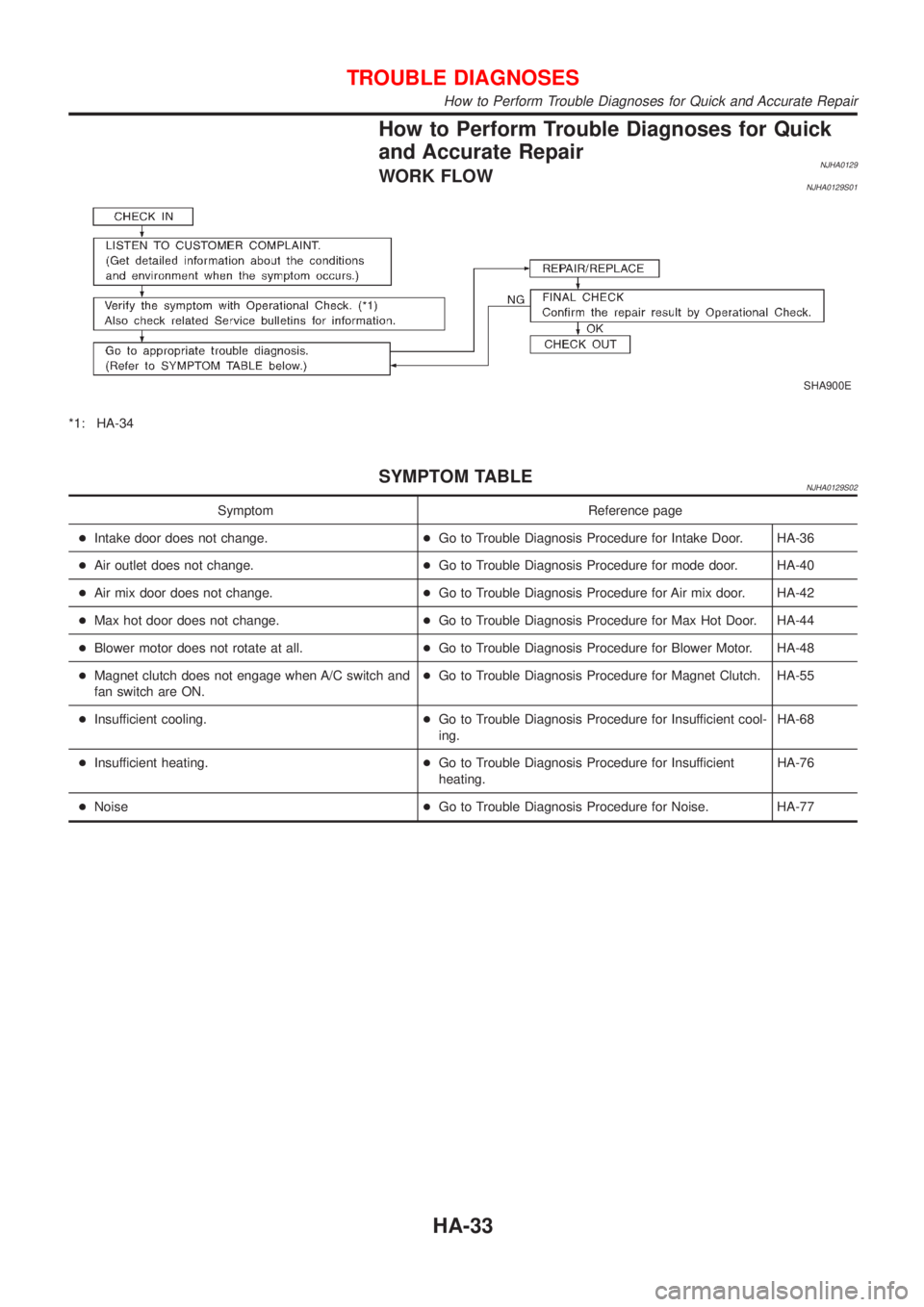
How to Perform Trouble Diagnoses for Quick
and Accurate Repair
NJHA0129WORK FLOWNJHA0129S01
SHA900E
*1: HA-34
SYMPTOM TABLENJHA0129S02
Symptom Reference page
+Intake door does not change.+Go to Trouble Diagnosis Procedure for Intake Door. HA-36
+Air outlet does not change.+Go to Trouble Diagnosis Procedure for mode door. HA-40
+Air mix door does not change.+Go to Trouble Diagnosis Procedure for Air mix door. HA-42
+Max hot door does not change.+Go to Trouble Diagnosis Procedure for Max Hot Door. HA-44
+Blower motor does not rotate at all.+Go to Trouble Diagnosis Procedure for Blower Motor. HA-48
+Magnet clutch does not engage when A/C switch and
fan switch are ON.+Go to Trouble Diagnosis Procedure for Magnet Clutch. HA-55
+Insufficient cooling.+Go to Trouble Diagnosis Procedure for Insufficient cool-
ing.HA-68
+Insufficient heating.+Go to Trouble Diagnosis Procedure for Insufficient
heating.HA-76
+Noise+Go to Trouble Diagnosis Procedure for Noise. HA-77
TROUBLE DIAGNOSES
How to Perform Trouble Diagnoses for Quick and Accurate Repair
HA-33
Page 2435 of 2898
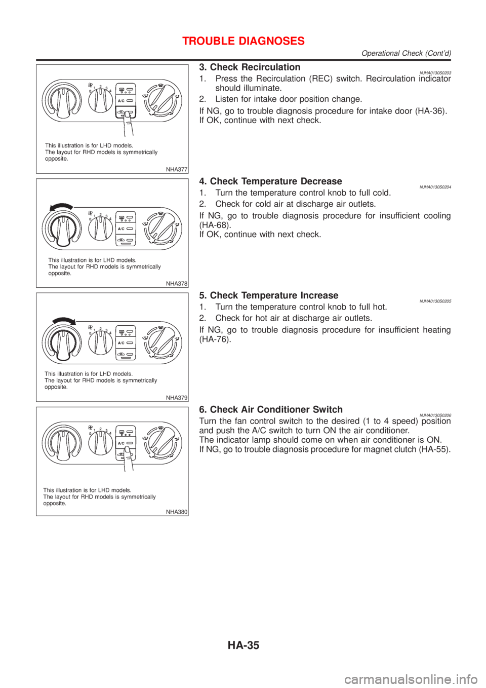
NHA377
3. Check RecirculationNJHA0130S02031. Press the Recirculation (REC) switch. Recirculation indicator
should illuminate.
2. Listen for intake door position change.
If NG, go to trouble diagnosis procedure for intake door (HA-36).
If OK, continue with next check.
NHA378
4. Check Temperature DecreaseNJHA0130S02041. Turn the temperature control knob to full cold.
2. Check for cold air at discharge air outlets.
If NG, go to trouble diagnosis procedure for insufficient cooling
(HA-68).
If OK, continue with next check.
NHA379
5. Check Temperature IncreaseNJHA0130S02051. Turn the temperature control knob to full hot.
2. Check for hot air at discharge air outlets.
If NG, go to trouble diagnosis procedure for insufficient heating
(HA-76).
NHA380
6. Check Air Conditioner SwitchNJHA0130S0206Turn the fan control switch to the desired (1 to 4 speed) position
and push the A/C switch to turn ON the air conditioner.
The indicator lamp should come on when air conditioner is ON.
If NG, go to trouble diagnosis procedure for magnet clutch (HA-55).
TROUBLE DIAGNOSES
Operational Check (Cont'd)
HA-35
Page 2476 of 2898
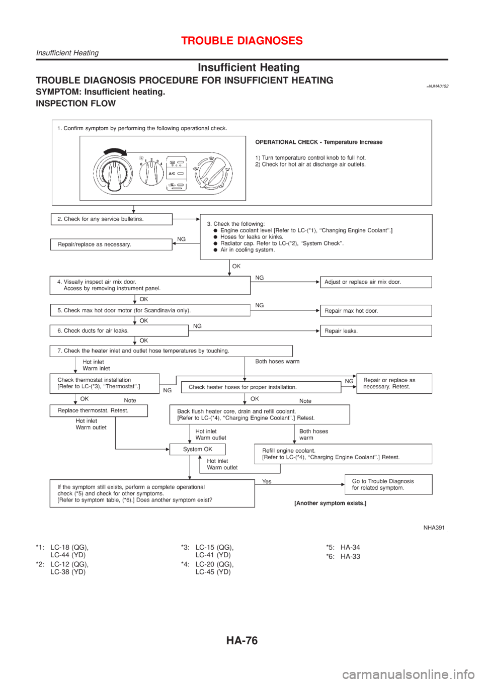
Insufficient Heating
TROUBLE DIAGNOSIS PROCEDURE FOR INSUFFICIENT HEATING=NJHA0152SYMPTOM: Insufficient heating.
INSPECTION FLOW
NHA391
*1: LC-18 (QG),
LC-44 (YD)
*2: LC-12 (QG),
LC-38 (YD)*3: LC-15 (QG),
LC-41 (YD)
*4: LC-20 (QG),
LC-45 (YD)*5: HA-34
*6: HA-33
TROUBLE DIAGNOSES
Insufficient Heating
HA-76
Page 2507 of 2898
ENGINE LUBRICATION &
COOLING SYSTEMS
SECTION
LC
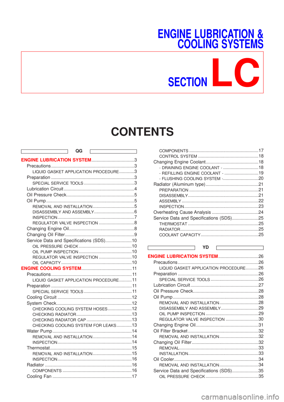
CONTENTS
QG
ENGINE LUBRICATION SYSTEM..................................3
Precautions ..................................................................3
LIQUID GASKET APPLICATION PROCEDURE............3
Preparation ..................................................................3
SPECIAL SERVICE TOOLS........................................3
Lubrication Circuit ........................................................4
Oil Pressure Check......................................................5
Oil Pump ......................................................................5
REMOVAL AND INSTALLATION.................................5
DISASSEMBLY AND ASSEMBLY................................6
INSPECTION.............................................................7
REGULATOR VALVE INSPECTION............................8
Changing Engine Oil....................................................8
Changing Oil Filter .......................................................9
Service Data and Specifications (SDS).....................10
OIL PRESSURE CHECK..........................................10
OIL PUMP INSPECTION..........................................10
REGULATOR VALVE INSPECTION..........................10
OIL CAPACITY........................................................10
ENGINE COOLING SYSTEM........................................ 11
Precautions ................................................................ 11
LIQUID GASKET APPLICATION PROCEDURE.......... 11
Preparation ................................................................ 11
SPECIAL SERVICE TOOLS...................................... 11
Cooling Circuit ...........................................................12
System Check............................................................12
CHECKING COOLING SYSTEM HOSES...................12
CHECKING RADIATOR............................................13
CHECKING RADIATOR CAP....................................13
CHECKING COOLING SYSTEM FOR LEAKS............13
Water Pump ...............................................................14
REMOVAL AND INSTALLATION...............................14
INSPECTION...........................................................14
Thermostat .................................................................15
REMOVAL AND INSTALLATION...............................15
INSPECTION...........................................................16
Radiator .....................................................................16
COMPONENTS.......................................................16
Cooling Fan ...............................................................17
COMPONENTS.......................................................17
CONTROL SYSTEM................................................18
Changing Engine Coolant..........................................18
- DRAINING ENGINE COOLANT -............................18
- REFILLING ENGINE COOLANT -...........................19
- FLUSHING COOLING SYSTEM -............................20
Radiator (Aluminum type) ..........................................21
PREPARATION.......................................................21
DISASSEMBLY........................................................21
ASSEMBLY.............................................................22
INSPECTION...........................................................23
Overheating Cause Analysis .....................................24
Service Data and Specifications (SDS).....................25
THERMOSTAT........................................................25
RADIATOR..............................................................25
COOLANT CAPACITY..............................................25
YD
ENGINE LUBRICATION SYSTEM................................26
Precautions ................................................................26
LIQUID GASKET APPLICATION PROCEDURE..........26
Preparation ................................................................26
SPECIAL SERVICE TOOLS......................................26
Lubrication Circuit ......................................................27
Oil Pressure Check....................................................28
Oil Pump ....................................................................28
REMOVAL AND INSTALLATION...............................28
DISASSEMBLY AND ASSEMBLY..............................29
OIL PUMP INSPECTION..........................................29
REGULATOR VALVE INSPECTION..........................30
Changing Engine Oil..................................................31
Oil Filter Bracket ........................................................32
REMOVAL AND INSTALLATION...............................32
Changing Oil Filter .....................................................32
REMOVAL...............................................................33
INSTALLATION........................................................33
Oil Cooler ...................................................................34
REMOVAL AND INSTALLATION...............................34
Service Data and Specifications (SDS).....................35
OIL PRESSURE CHECK..........................................35
Page 2508 of 2898
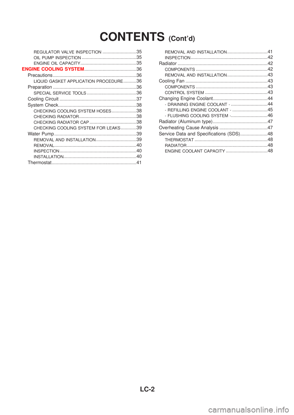
REGULATOR VALVE INSPECTION..........................35
OIL PUMP INSPECTION..........................................35
ENGINE OIL CAPACITY...........................................35
ENGINE COOLING SYSTEM........................................36
Precautions ................................................................36
LIQUID GASKET APPLICATION PROCEDURE..........36
Preparation ................................................................36
SPECIAL SERVICE TOOLS......................................36
Cooling Circuit ...........................................................37
System Check............................................................38
CHECKING COOLING SYSTEM HOSES...................38
CHECKING RADIATOR............................................38
CHECKING RADIATOR CAP....................................38
CHECKING COOLING SYSTEM FOR LEAKS............39
Water Pump ...............................................................39
REMOVAL AND INSTALLATION...............................39
REMOVAL...............................................................40
INSPECTION...........................................................40
INSTALLATION........................................................40
Thermostat .................................................................41
REMOVAL AND INSTALLATION...............................41
INSPECTION...........................................................42
Radiator .....................................................................42
COMPONENTS.......................................................42
REMOVAL AND INSTALLATION...............................43
Cooling Fan ...............................................................43
COMPONENTS.......................................................43
CONTROL SYSTEM................................................43
Changing Engine Coolant..........................................44
- DRAINING ENGINE COOLANT -............................44
- REFILLING ENGINE COOLANT -...........................45
- FLUSHING COOLING SYSTEM -............................46
Radiator (Aluminum type) ..........................................47
Overheating Cause Analysis .....................................47
Service Data and Specifications (SDS).....................48
THERMOSTAT........................................................48
RADIATOR..............................................................48
ENGINE COOLANT CAPACITY................................48
CONTENTS(Cont'd)
LC-2
Page 2530 of 2898
SLC934
2. Check for leakage.
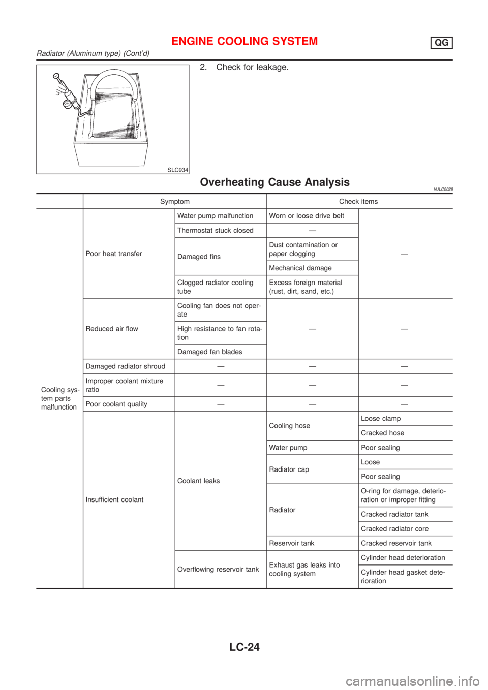
Overheating Cause AnalysisNJLC0028
Symptom Check items
Cooling sys-
tem parts
malfunctionPoor heat transferWater pump malfunction Worn or loose drive belt
Ð Thermostat stuck closed Ð
Damaged finsDust contamination or
paper clogging
Mechanical damage
Clogged radiator cooling
tubeExcess foreign material
(rust, dirt, sand, etc.)
Reduced air flowCooling fan does not oper-
ate
ÐÐ High resistance to fan rota-
tion
Damaged fan blades
Damaged radiator shroud Ð Ð Ð
Improper coolant mixture
ratioÐÐÐ
Poor coolant quality Ð Ð Ð
Insufficient coolantCoolant leaksCooling hoseLoose clamp
Cracked hose
Water pump Poor sealing
Radiator capLoose
Poor sealing
RadiatorO-ring for damage, deterio-
ration or improper fitting
Cracked radiator tank
Cracked radiator core
Reservoir tank Cracked reservoir tank
Overflowing reservoir tankExhaust gas leaks into
cooling systemCylinder head deterioration
Cylinder head gasket dete-
rioration
ENGINE COOLING SYSTEMQG
Radiator (Aluminum type) (Cont'd)
LC-24
Page 2531 of 2898
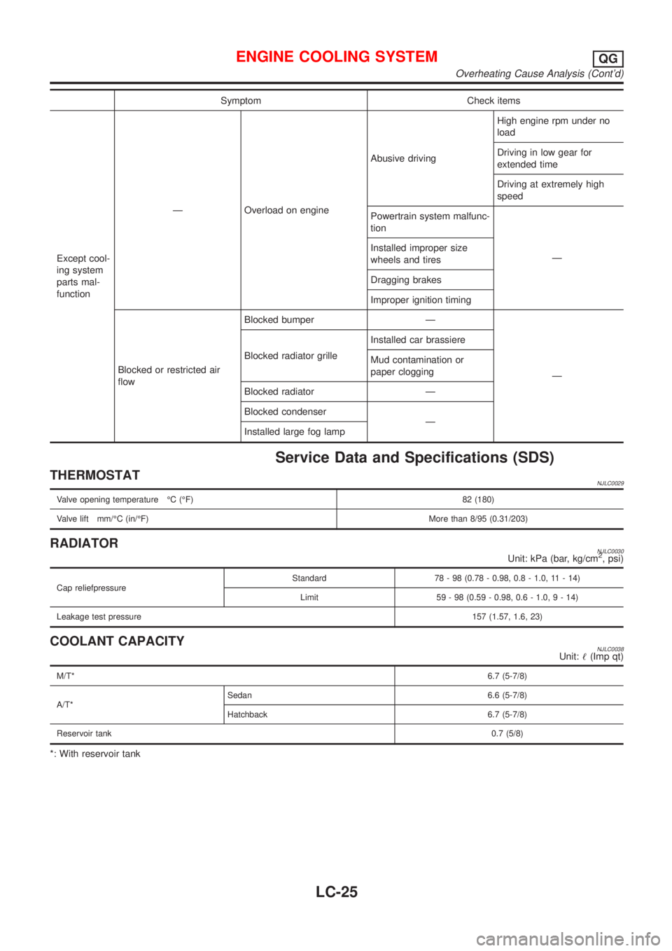
Symptom Check items
Except cool-
ing system
parts mal-
functionÐ Overload on engineAbusive drivingHigh engine rpm under no
load
Driving in low gear for
extended time
Driving at extremely high
speed
Powertrain system malfunc-
tion
Ð Installed improper size
wheels and tires
Dragging brakes
Improper ignition timing
Blocked or restricted air
flowBlocked bumper Ð
Ð Blocked radiator grilleInstalled car brassiere
Mud contamination or
paper clogging
Blocked radiator Ð
Blocked condenser
Ð
Installed large fog lamp
Service Data and Specifications (SDS)
THERMOSTATNJLC0029
Valve opening temperature ÉC (ÉF) 82 (180)
Valve lift mm/ÉC (in/ÉF)More than 8/95 (0.31/203)
RADIATORNJLC0030Unit: kPa (bar, kg/cm2, psi)
Cap reliefpressureStandard 78 - 98 (0.78 - 0.98, 0.8 - 1.0, 11 - 14)
Limit 59 - 98 (0.59 - 0.98, 0.6 - 1.0,9-14)
Leakage test pressure157 (1.57, 1.6, 23)
COOLANT CAPACITYNJLC0038Unit:!(Imp qt)
M/T*6.7 (5-7/8)
A/T*Sedan 6.6 (5-7/8)
Hatchback 6.7 (5-7/8)
Reservoir tank0.7 (5/8)
*: With reservoir tank
ENGINE COOLING SYSTEMQG
Overheating Cause Analysis (Cont'd)
LC-25