2001 NISSAN ALMERA fuel filter
[x] Cancel search: fuel filterPage 716 of 2898
SCL729
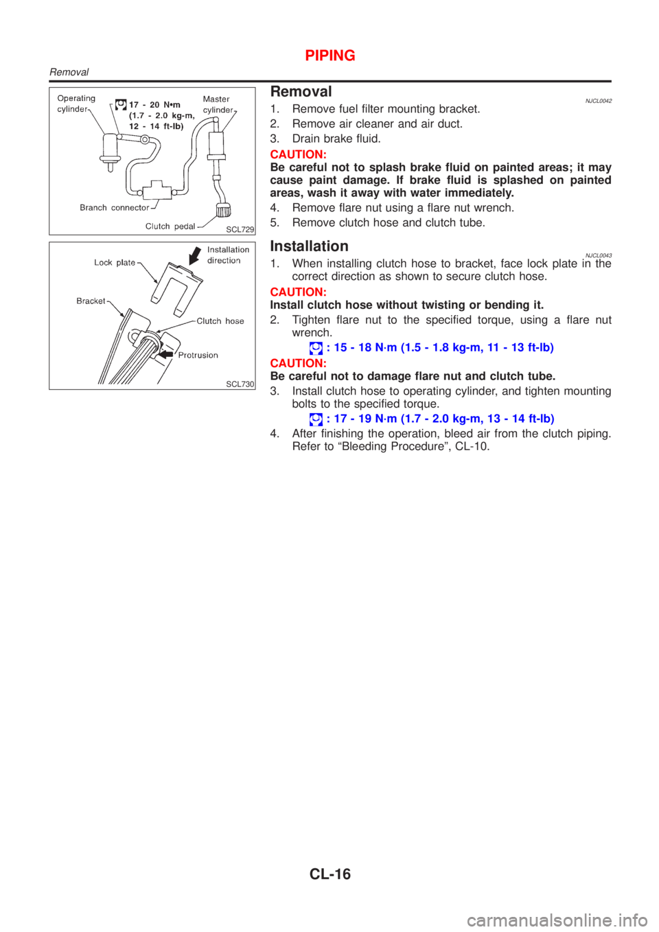
RemovalNJCL00421. Remove fuel filter mounting bracket.
2. Remove air cleaner and air duct.
3. Drain brake fluid.
CAUTION:
Be careful not to splash brake fluid on painted areas; it may
cause paint damage. If brake fluid is splashed on painted
areas, wash it away with water immediately.
4. Remove flare nut using a flare nut wrench.
5. Remove clutch hose and clutch tube.
SCL730
InstallationNJCL00431. When installing clutch hose to bracket, face lock plate in the
correct direction as shown to secure clutch hose.
CAUTION:
Install clutch hose without twisting or bending it.
2. Tighten flare nut to the specified torque, using a flare nut
wrench.
: 15 - 18 N´m (1.5 - 1.8 kg-m, 11 - 13 ft-lb)
CAUTION:
Be careful not to damage flare nut and clutch tube.
3. Install clutch hose to operating cylinder, and tighten mounting
bolts to the specified torque.
: 17 - 19 N´m (1.7 - 2.0 kg-m, 13 - 14 ft-lb)
4. After finishing the operation, bleed air from the clutch piping.
Refer to ªBleeding Procedureº, CL-10.
PIPING
Removal
CL-16
Page 731 of 2898

ECM Terminals and Reference Value .....................578
Wiring Diagram ........................................................579
Diagnostic Procedure - Load Signal - .....................583
Diagnostic Procedure - Heater Control Panel
(Fan Switch) - ..........................................................589
Component Inspection .............................................590
MI & DATA LINK CONNECTORS..............................591
Wiring Diagram ........................................................591
SERVICE DATA AND SPECIFICATIONS (SDS).......593
Fuel Pressure Regulator..........................................593
Idle Speed and Ignition Timing ................................593
Mass Air Flow Sensor..............................................593
Intake Air Temperature Sensor ................................593
Engine Coolant Temperature Sensor ......................593
Throttle Position Sensor ..........................................593
Heated Oxygen Sensor 1 Heater (Front) ................593
Heated Oxygen Sensor 2 Heater (Rear).................593
Fuel Tank Temperature Sensor (Where Fitted) .......594
EGR Volume Control Valve (Where Fitted) .............594
EGR Temperature Sensor (Where Fitted) ...............594
EVAP Canister Purge Volume Control Valve ..........594
IACV-AAC Valve ......................................................594
Injector .....................................................................594
Ignition Coil with Power Transistor ..........................594
Condenser ...............................................................594
Fuel Pump ...............................................................594
Crankshaft Position Sensor (POS) ..........................595
Camshaft Position Sensor (PHASE) .......................595
YD
TROUBLE DIAGNOSIS - INDEX................................596
Alphabetical & P No. Index for DTC .......................596
PRECAUTIONS...........................................................598
Supplemental Restraint System (SRS)²AIR
BAG²and²SEAT BELT PRE-TENSIONER²...........598
Engine Fuel & Emission Control System ................599
Precautions ..............................................................600
Wiring Diagrams and Trouble Diagnosis .................601
PREPARATION...........................................................602
Special Service Tools ..............................................602
ENGINE AND EMISSION CONTROL OVERALL
SYSTEM.......................................................................603
Engine Control Component Parts Location .............603
Circuit Diagram ........................................................606
System Diagram ......................................................608
System Chart ...........................................................609
ENGINE AND EMISSION BASIC CONTROL
SYSTEM DESCRIPTION.............................................610
Fuel Injection Control System .................................610
Fuel Injection Timing Control System...................... 611
Air Conditioning Cut Control ....................................612Fuel Cut Control (at no load & high engine
speed) ......................................................................612
Crankcase Ventilation System .................................613
BASIC SERVICE PROCEDURE.................................614
Injection Tube and Injection Nozzle ........................614
Electronic Control Fuel Injection Pump ...................618
Fuel Filter .................................................................625
ON BOARD DIAGNOSTIC SYSTEM
DESCRIPTION.............................................................627
DTC and MI Detection Logic ...................................627
Diagnostic Trouble Code (DTC) ..............................627
Malfunction Indicator (MI) ........................................628
CONSULT-II .............................................................632
TROUBLE DIAGNOSIS - INTRODUCTION................637
Introduction ..............................................................637
Work Flow ................................................................639
TROUBLE DIAGNOSIS - BASIC INSPECTION.........641
Basic Inspection.......................................................641
TROUBLE DIAGNOSIS - GENERAL
DESCRIPTION.............................................................646
Symptom Matrix Chart .............................................646
CONSULT-II Reference Value in Data Monitor
Mode ........................................................................656
Major Sensor Reference Graph in Data Monitor
Mode ........................................................................658
ECM Terminals and Reference Value .....................659
TROUBLE DIAGNOSIS FOR INTERMITTENT
INCIDENT.....................................................................665
Description ...............................................................665
Diagnostic Procedure ..............................................665
TROUBLE DIAGNOSIS FOR POWER SUPPLY........666
Main Power Supply and Ground Circuit ..................666
DTC P0100 MASS AIR FLOW SEN...........................673
Component Description ...........................................673
CONSULT-II Reference Value in Data Monitor
Mode ........................................................................673
ECM Terminals and Reference Value .....................673
On Board Diagnosis Logic.......................................673
DTC Confirmation Procedure ..................................673
Wiring Diagram ........................................................675
Diagnostic Procedure ..............................................677
DTC P0115 COOLANT TEMP SEN............................680
Description ...............................................................680
On Board Diagnosis Logic.......................................680
DTC Confirmation Procedure ..................................680
Wiring Diagram ........................................................682
Diagnostic Procedure ..............................................683
DTC P0120 ACCEL POS SENSOR............................685
Description ...............................................................685
CONSULT-II Reference Value in Data Monitor
Mode ........................................................................685
ECM Terminals and Reference Value .....................685
CONTENTS(Cont'd)
EC-7
Page 764 of 2898
SEF094Y
SEF214Y
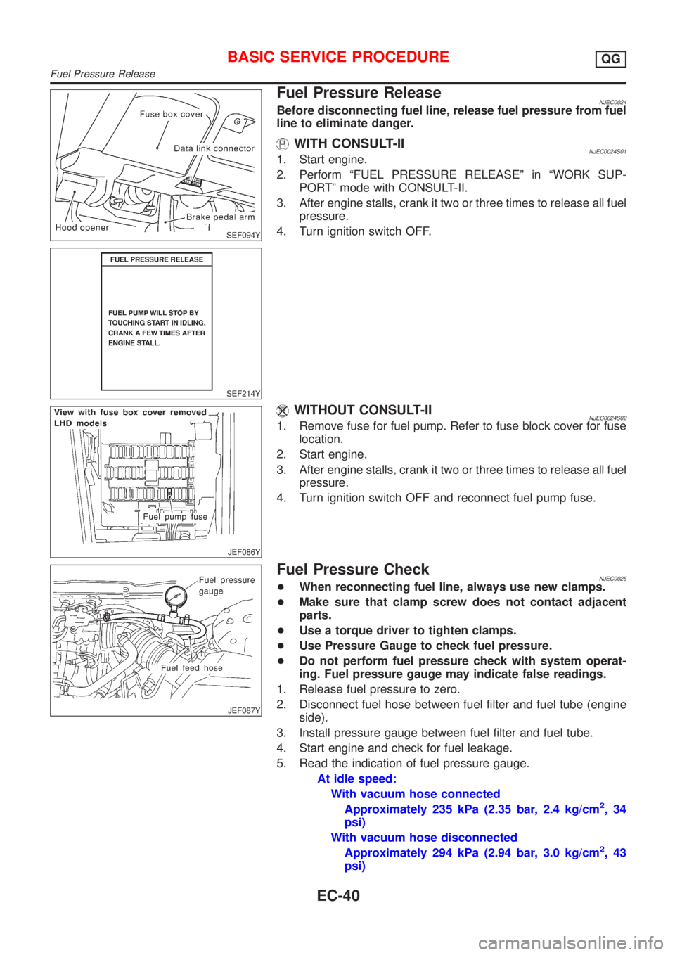
Fuel Pressure ReleaseNJEC0024Before disconnecting fuel line, release fuel pressure from fuel
line to eliminate danger.
WITH CONSULT-IINJEC0024S011. Start engine.
2. Perform ªFUEL PRESSURE RELEASEº in ªWORK SUP-
PORTº mode with CONSULT-II.
3. After engine stalls, crank it two or three times to release all fuel
pressure.
4. Turn ignition switch OFF.
JEF086Y
WITHOUT CONSULT-IINJEC0024S021. Remove fuse for fuel pump. Refer to fuse block cover for fuse
location.
2. Start engine.
3. After engine stalls, crank it two or three times to release all fuel
pressure.
4. Turn ignition switch OFF and reconnect fuel pump fuse.
JEF087Y
Fuel Pressure CheckNJEC0025+When reconnecting fuel line, always use new clamps.
+Make sure that clamp screw does not contact adjacent
parts.
+Use a torque driver to tighten clamps.
+Use Pressure Gauge to check fuel pressure.
+Do not perform fuel pressure check with system operat-
ing. Fuel pressure gauge may indicate false readings.
1. Release fuel pressure to zero.
2. Disconnect fuel hose between fuel filter and fuel tube (engine
side).
3. Install pressure gauge between fuel filter and fuel tube.
4. Start engine and check for fuel leakage.
5. Read the indication of fuel pressure gauge.
At idle speed:
With vacuum hose connected
Approximately 235 kPa (2.35 bar, 2.4 kg/cm
2,34
psi)
With vacuum hose disconnected
Approximately 294 kPa (2.94 bar, 3.0 kg/cm
2,43
psi)
BASIC SERVICE PROCEDUREQG
Fuel Pressure Release
EC-40
Page 882 of 2898
SYMPTOM
Reference
page
HARD/NO START/RESTART (EXCP. HA)
ENGINE STALL
HESITATION/SURGING/FLAT SPOT
SPARK KNOCK/DETONATION
LACK OF POWER/POOR ACCELERATION
HIGH IDLE/LOW IDLE
ROUGH IDLE/HUNTING
IDLING VIBRATION
SLOW/NO RETURN TO IDLE
OVERHEATS/WATER TEMPERATURE HIGH
EXCESSIVE FUEL CONSUMPTION
EXCESSIVE OIL CONSUMPTION
BATTERY DEAD (UNDER CHARGE)
Warranty symptom code AA AB AC AD AE AF AG AH AJ AK AL AM HA
Engine Cylinder head
55555 55 5
EM section Cylinder head gasket 4 3
Cylinder block
66666 66 64 Piston
Piston ring
Connecting rod
Bearing
Crankshaft
Valve
mecha-
nismTiming chain
55555 55 5 EMsection Camshaft
Intake valve
3
Exhaust valve
Exhaust Exhaust manifold/Tube/
Muffler/Gasket
55555 55 5 FEsection
Three way catalyst
Lubrica-
tionOil pan/Oil strainer/Oil
pump/Oil filter/Oil gallery
55555 55 5MA, EM and
LC sections
Oil level (Low)/Filthy oil
LC section Cooling Radiator/Hose/Radiator filler
cap
55555 55 45 Thermostat 5
Water pump
Water gallery
Cooling fan 5 EC-406
Coolant level (low)/
Contaminated coolantMA section
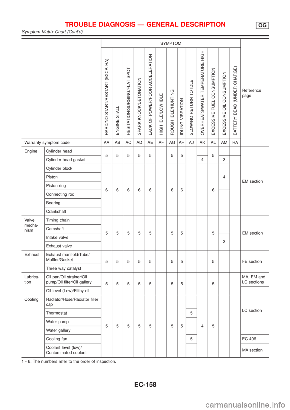
1 - 6: The numbers refer to the order of inspection.
TROUBLE DIAGNOSIS Ð GENERAL DESCRIPTIONQG
Symptom Matrix Chart (Cont'd)
EC-158
Page 1026 of 2898
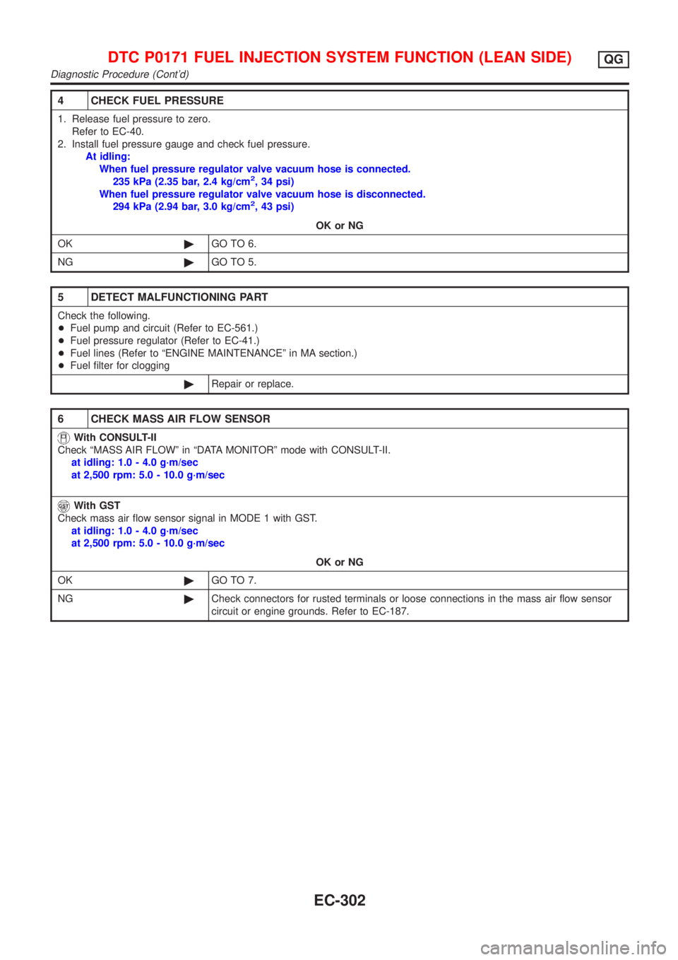
4 CHECK FUEL PRESSURE
1. Release fuel pressure to zero.
Refer to EC-40.
2. Install fuel pressure gauge and check fuel pressure.
At idling:
When fuel pressure regulator valve vacuum hose is connected.
235 kPa (2.35 bar, 2.4 kg/cm
2, 34 psi)
When fuel pressure regulator valve vacuum hose is disconnected.
294 kPa (2.94 bar, 3.0 kg/cm
2, 43 psi)
OK or NG
OK©GO TO 6.
NG©GO TO 5.
5 DETECT MALFUNCTIONING PART
Check the following.
+Fuel pump and circuit (Refer to EC-561.)
+Fuel pressure regulator (Refer to EC-41.)
+Fuel lines (Refer to ªENGINE MAINTENANCEº in MA section.)
+Fuel filter for clogging
©Repair or replace.
6 CHECK MASS AIR FLOW SENSOR
With CONSULT-II
Check ªMASS AIR FLOWº in ªDATA MONITORº mode with CONSULT-II.
at idling: 1.0 - 4.0 g´m/sec
at 2,500 rpm: 5.0 - 10.0 g´m/sec
With GST
Check mass air flow sensor signal in MODE 1 with GST.
at idling: 1.0 - 4.0 g´m/sec
at 2,500 rpm: 5.0 - 10.0 g´m/sec
OK or NG
OK©GO TO 7.
NG©Check connectors for rusted terminals or loose connections in the mass air flow sensor
circuit or engine grounds. Refer to EC-187.
DTC P0171 FUEL INJECTION SYSTEM FUNCTION (LEAN SIDE)QG
Diagnostic Procedure (Cont'd)
EC-302
Page 1046 of 2898
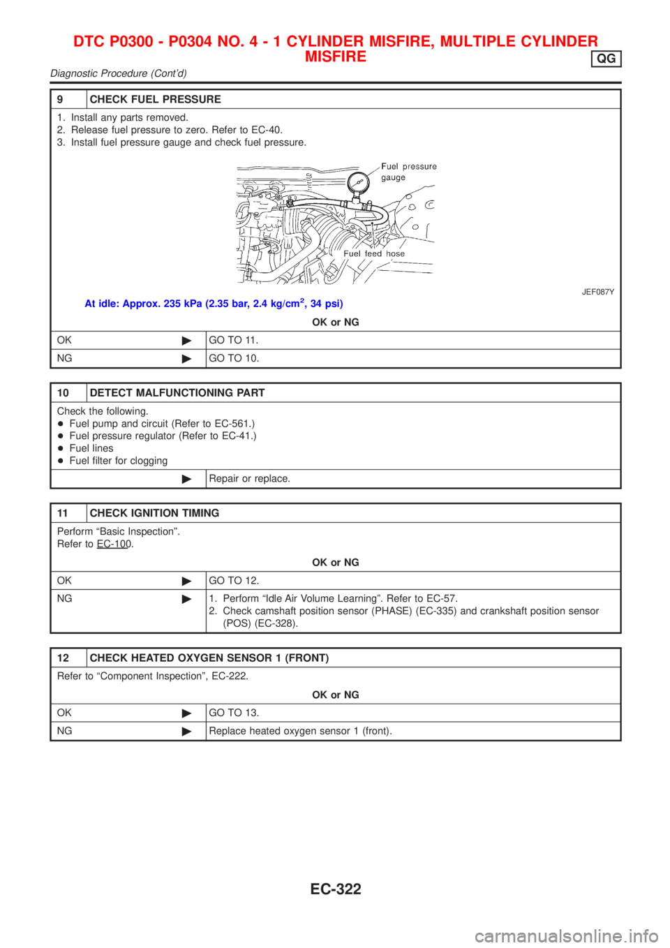
9 CHECK FUEL PRESSURE
1. Install any parts removed.
2. Release fuel pressure to zero. Refer to EC-40.
3. Install fuel pressure gauge and check fuel pressure.
JEF087Y
At idle: Approx. 235 kPa (2.35 bar, 2.4 kg/cm2, 34 psi)OK or NG
OK ©GO TO 11.
NG ©GO TO 10.
10 DETECT MALFUNCTIONING PART
Check the following.
+Fuel pump and circuit (Refer to EC-561.)
+ Fuel pressure regulator (Refer to EC-41.)
+ Fuel lines
+ Fuel filter for clogging
©Repair or replace.
11 CHECK IGNITION TIMING
Perform ªBasic Inspectionº.
Referto EC- 100.
OK or NG
OK ©GO TO 12.
NG ©1. Perform ªIdle Air Volume Learningº. Refer to EC-57.
2. Check camshaft position sensor (PHASE) (EC-335) and crankshaft position sensor
(POS) (EC-328).
12 CHECK HEATED OXYGEN SENSOR 1 (FRONT)
Refer to ªComponent Inspectionº, EC-222.
OK or NG
OK ©GO TO 13.
NG ©Replace heated oxygen sensor 1 (front).
DTC P0300 - P0304 NO .4-1CYLINDER MISFIRE, MULTIPLE CYLINDER
MISFIRE
QG
Diagnostic Procedure(Cont'd)
EC-322
Page 1324 of 2898
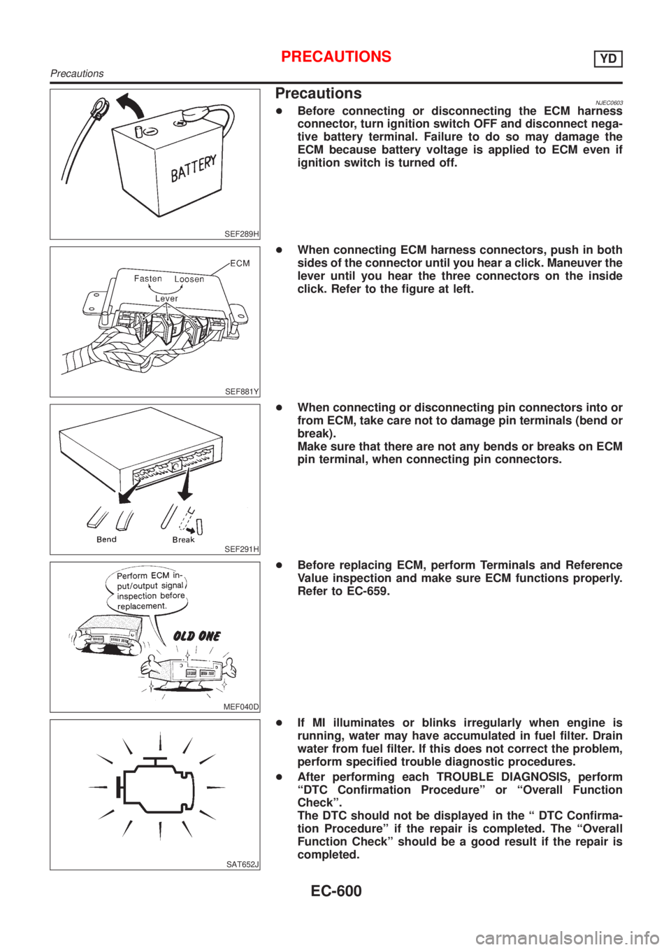
SEF289H
PrecautionsNJEC0603+Before connecting or disconnecting the ECM harness
connector, turn ignition switch OFF and disconnect nega-
tive battery terminal. Failure to do so may damage the
ECM because battery voltage is applied to ECM even if
ignition switch is turned off.
SEF881Y
+When connecting ECM harness connectors, push in both
sides of the connector until you hear a click. Maneuver the
lever until you hear the three connectors on the inside
click. Refer to the figure at left.
SEF291H
+When connecting or disconnecting pin connectors into or
from ECM, take care not to damage pin terminals (bend or
break).
Make sure that there are not any bends or breaks on ECM
pin terminal, when connecting pin connectors.
MEF040D
+Before replacing ECM, perform Terminals and Reference
Value inspection and make sure ECM functions properly.
Refer to EC-659.
SAT652J
+If MI illuminates or blinks irregularly when engine is
running, water may have accumulated in fuel filter. Drain
water from fuel filter. If this does not correct the problem,
perform specified trouble diagnostic procedures.
+After performing each TROUBLE DIAGNOSIS, perform
ªDTC Confirmation Procedureº or ªOverall Function
Checkº.
The DTC should not be displayed in the ª DTC Confirma-
tion Procedureº if the repair is completed. The ªOverall
Function Checkº should be a good result if the repair is
completed.
PRECAUTIONSYD
Precautions
EC-600
Page 1349 of 2898
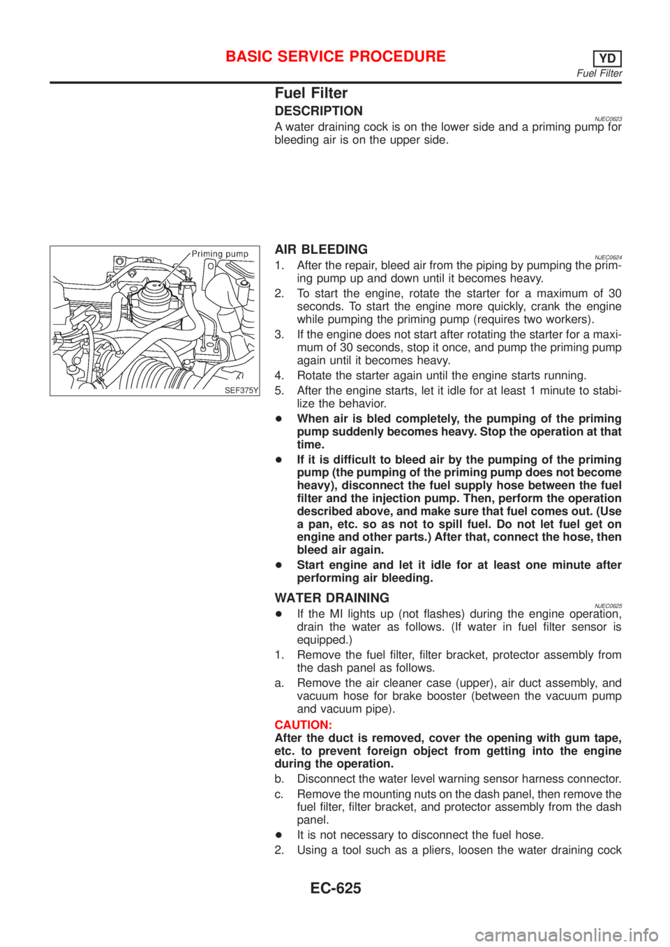
Fuel Filter
DESCRIPTIONNJEC0623A water draining cock is on the lower side and a priming pump for
bleeding air is on the upper side.
SEF375Y
AIR BLEEDINGNJEC06241. After the repair, bleed air from the piping by pumping the prim-
ing pump up and down until it becomes heavy.
2. To start the engine, rotate the starter for a maximum of 30
seconds. To start the engine more quickly, crank the engine
while pumping the priming pump (requires two workers).
3. If the engine does not start after rotating the starter for a maxi-
mum of 30 seconds, stop it once, and pump the priming pump
again until it becomes heavy.
4. Rotate the starter again until the engine starts running.
5. After the engine starts, let it idle for at least 1 minute to stabi-
lize the behavior.
+When air is bled completely, the pumping of the priming
pump suddenly becomes heavy. Stop the operation at that
time.
+If it is difficult to bleed air by the pumping of the priming
pump (the pumping of the priming pump does not become
heavy), disconnect the fuel supply hose between the fuel
filter and the injection pump. Then, perform the operation
described above, and make sure that fuel comes out. (Use
a pan, etc. so as not to spill fuel. Do not let fuel get on
engine and other parts.) After that, connect the hose, then
bleed air again.
+Start engine and let it idle for at least one minute after
performing air bleeding.
WATER DRAININGNJEC0625+If the MI lights up (not flashes) during the engine operation,
drain the water as follows. (If water in fuel filter sensor is
equipped.)
1. Remove the fuel filter, filter bracket, protector assembly from
the dash panel as follows.
a. Remove the air cleaner case (upper), air duct assembly, and
vacuum hose for brake booster (between the vacuum pump
and vacuum pipe).
CAUTION:
After the duct is removed, cover the opening with gum tape,
etc. to prevent foreign object from getting into the engine
during the operation.
b. Disconnect the water level warning sensor harness connector.
c. Remove the mounting nuts on the dash panel, then remove the
fuel filter, filter bracket, and protector assembly from the dash
panel.
+It is not necessary to disconnect the fuel hose.
2. Using a tool such as a pliers, loosen the water draining cock
BASIC SERVICE PROCEDUREYD
Fuel Filter
EC-625