Page 10 of 2898

AAT470A
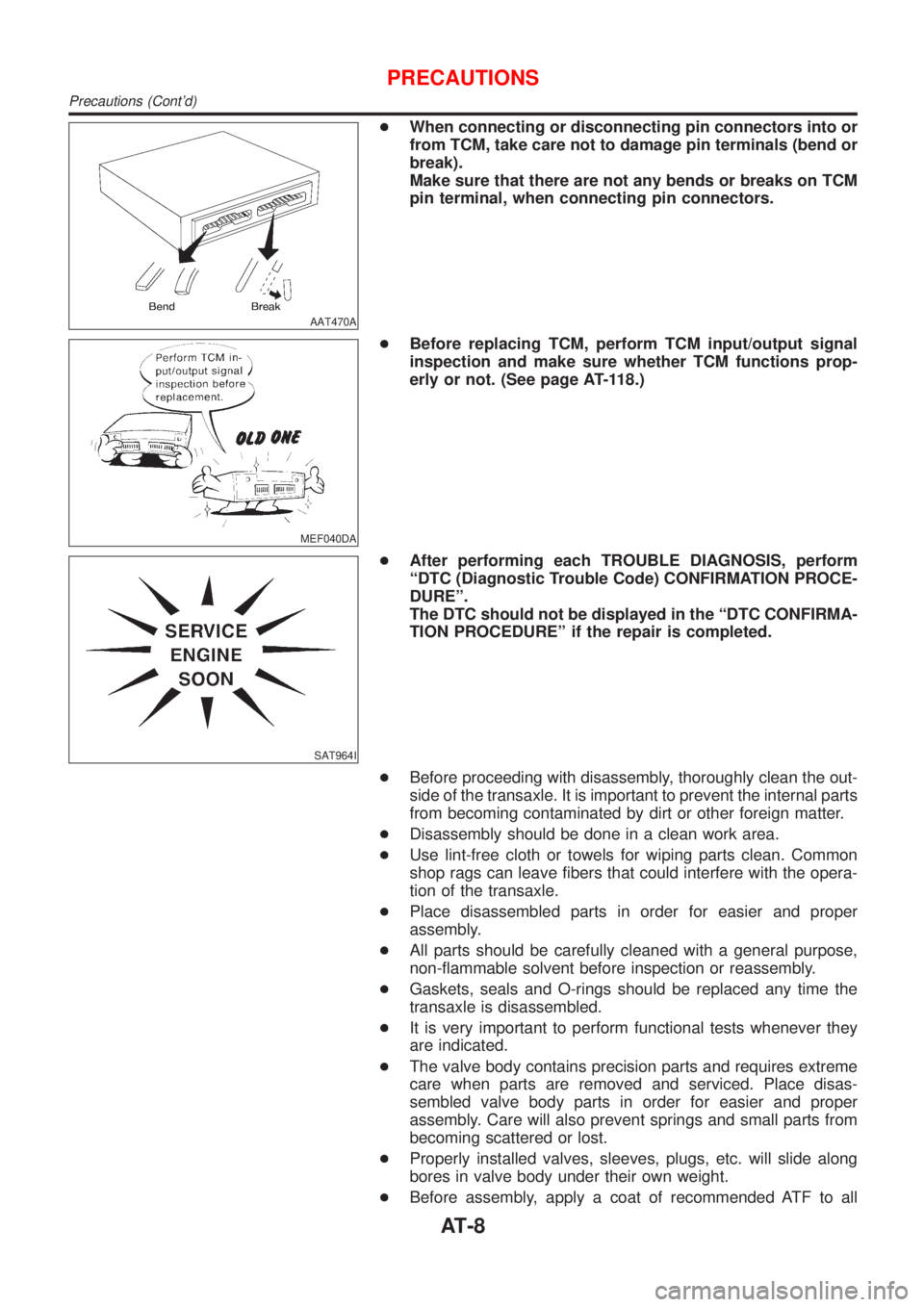
+When connecting or disconnecting pin connectors into or
from TCM, take care not to damage pin terminals (bend or
break).
Make sure that there are not any bends or breaks on TCM
pin terminal, when connecting pin connectors.
MEF040DA
+Before replacing TCM, perform TCM input/output signal
inspection and make sure whether TCM functions prop-
erly or not. (See page AT-118.)
SAT964I
+After performing each TROUBLE DIAGNOSIS, perform
ªDTC (Diagnostic Trouble Code) CONFIRMATION PROCE-
DUREº.
The DTC should not be displayed in the ªDTC CONFIRMA-
TION PROCEDUREº if the repair is completed.
+Before proceeding with disassembly, thoroughly clean the out-
side of the transaxle. It is important to prevent the internal parts
from becoming contaminated by dirt or other foreign matter.
+Disassembly should be done in a clean work area.
+Use lint-free cloth or towels for wiping parts clean. Common
shop rags can leave fibers that could interfere with the opera-
tion of the transaxle.
+Place disassembled parts in order for easier and proper
assembly.
+All parts should be carefully cleaned with a general purpose,
non-flammable solvent before inspection or reassembly.
+Gaskets, seals and O-rings should be replaced any time the
transaxle is disassembled.
+It is very important to perform functional tests whenever they
are indicated.
+The valve body contains precision parts and requires extreme
care when parts are removed and serviced. Place disas-
sembled valve body parts in order for easier and proper
assembly. Care will also prevent springs and small parts from
becoming scattered or lost.
+Properly installed valves, sleeves, plugs, etc. will slide along
bores in valve body under their own weight.
+Before assembly, apply a coat of recommended ATF to all
PRECAUTIONS
Precautions (Cont'd)
AT-8
Page 211 of 2898

2 CHECK CONTROL VALVE
1. Disassemble control valve assembly. Refer to ªControl Valve Assemblyº, AT-388.
2. Check to ensure that:
+Valve, sleeve and plug slide along valve bore under their own weight.
+Valve, sleeve and plug are free from burrs, dents and scratches.
+Control valve springs are free from damage, deformation and fatigue.
+Hydraulic line is free from obstacles.
SAT367H
OK or NG
OK©GO TO 3.
NG©Repair control valve assembly.
3 CHECK DTC
Perform Diagnostic Trouble Code (DTC) confirmation procedure, AT-205.
OK or NG
OK©INSPECTION END
NG©Check control valve again. Repair or replace control valve assembly.
SAT050KA
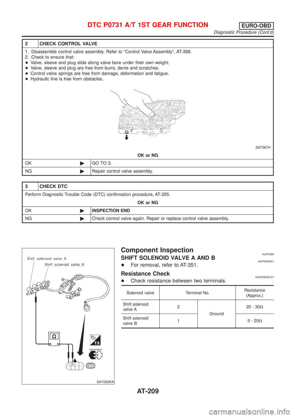
Component InspectionNJAT0282SHIFT SOLENOID VALVE A AND BNJAT0282S01+For removal, refer to AT-351.
Resistance CheckNJAT0282S0101+Check resistance between two terminals.
Solenoid valve Terminal No.Resistance
(Approx.)
Shift solenoid
valve A2
Ground20-30W
Shift solenoid
valve B1 5-20W
DTC P0731 A/T 1ST GEAR FUNCTIONEURO-OBD
Diagnostic Procedure (Cont'd)
AT-209
Page 217 of 2898
Diagnostic ProcedureNJAT0285
1 CHECK SHIFT SOLENOID VALVE
1. Remove control valve assembly. Refer to AT-351.
2. Check shift solenoid valve operation.
+Shift solenoid valve B
Refer to ªComponent Inspectionº, AT-216.
SAT884JB
OK or NG
OK©GO TO 2.
NG©Repair or replace shift solenoid valve assembly.
2 CHECK CONTROL VALVE
1. Disassemble control valve assembly. Refer to ªControl Valve Assemblyº, AT-388.
2. Check to ensure that:
+Valve, sleeve and plug slide along valve bore under their own weight.
+Valve, sleeve and plug are free from burrs, dents and scratches.
+Control valve springs are free from damage, deformation and fatigue.
+Hydraulic line is free from obstacles.
SAT367H
OK or NG
OK©GO TO 3.
NG©Repair control valve assembly.
DTC P0732 A/T 2ND GEAR FUNCTIONEURO-OBD
Diagnostic Procedure
AT-215
Page 223 of 2898
Diagnostic ProcedureNJAT0289
1 CHECK SHIFT SOLENOID VALVE
1. Remove control valve assembly. Refer to AT-351.
2. Check shift solenoid valve operation.
+Shift solenoid valve A
Refer to ªComponent Inspectionº below.
SAT886JA
OK or NG
OK©GO TO 2.
NG©Repair or replace shift solenoid valve assembly.
2 CHECK CONTROL VALVE
1. Disassemble control valve assembly. Refer to ªControl Valve Assemblyº, AT-388.
2. Check to ensure that:
+Valve, sleeve and plug slide along valve bore under their own weight.
+Valve, sleeve and plug are free from burrs, dents and scratches.
+Control valve springs are free from damage, deformation and fatigue.
+Hydraulic line is free from obstacles.
SAT367H
OK or NG
OK©GO TO 3.
NG©Repair control valve assembly.
DTC P0733 A/T 3RD GEAR FUNCTIONEURO-OBD
Diagnostic Procedure
AT-221
Page 231 of 2898
3 CHECK SOLENOID VALVES
1. Remove control valve assembly.
Refer to AT-351.
2. Refer to ªComponent Inspectionº, AT-232.
SAT847JB
OK or NG
OK©GO TO 4.
NG©Replace solenoid valve assembly.
4 CHECK CONTROL VALVE
1. Disassemble control valve assembly.
Refer to AT-388.
2. Check to ensure that:
+Valve, sleeve and plug slide along valve bore under their own weight.
+Valve, sleeve and plug are free from burrs, dents and scratches.
+Control valve springs are free from damage, deformation and fatigue.
+Hydraulic line is free from obstacles.
SAT367H
OK or NG
OK©GO TO 5.
NG©Repair control valve.
DTC P0734 A/T 4TH GEAR FUNCTIONEURO-OBD
Diagnostic Procedure (Cont'd)
AT-229
Page 881 of 2898

SYSTEM Ð ENGINE MECHANICAL & OTHERNJEC0041S03
SYMPTOM
Reference
page
HARD/NO START/RESTART (EXCP. HA)
ENGINE STALL
HESITATION/SURGING/FLAT SPOT
SPARK KNOCK/DETONATION
LACK OF POWER/POOR ACCELERATION
HIGH IDLE/LOW IDLE
ROUGH IDLE/HUNTING
IDLING VIBRATION
SLOW/NO RETURN TO IDLE
OVERHEATS/WATER TEMPERATURE HIGH
EXCESSIVE FUEL CONSUMPTION
EXCESSIVE OIL CONSUMPTION
BATTERY DEAD (UNDER CHARGE)
Warranty symptom code AA AB AC AD AE AF AG AH AJ AK AL AM HA
Fuel Fuel tank
5
5FE section
Fuel piping 5 5 5 5 5 5
Ð Vapor lock
Valve deposit
5 555 55 5
Poor fuel (Heavy weight
gasoline, Low octane)
Air Air duct
55555 5 Air cleaner
Air leakage from air duct
(Mass air flow sensor Ð
throttle body)
5555
Throttle body, Throttle wireFE section
Air leakage from intake
manifold/Collector/GasketÐ
Cranking Battery
111111 11
EL section Alternator circuit
Starter circuit 3
Flywheel/drive plate 6EM section
1 - 6: The numbers refer to the order of inspection.
(continued on next page)
TROUBLE DIAGNOSIS Ð GENERAL DESCRIPTIONQG
Symptom Matrix Chart (Cont'd)
EC-157
Page 1623 of 2898
Aiming AdjustmentNJEL0016For details, refer to the regulations in your own country.
Before performing aiming adjustment, check the following.
1) Keep all tires inflated to correct pressures.
2) Place vehicle on flat surface.
3) See that there is no-load in vehicle (coolant, engine oil filled up
to correct level and full fuel tank) other than the driver (or
equivalent weight placed in driver's position).
SEL984W
CAUTION:
Be sure aiming switch is set to ª0º when performing aiming
adjustment on vehicles equipped with headlamp aiming con-
trol.
HEADLAMP
Aiming Adjustment
EL-65
Page 1650 of 2898

SEL976W
SEL480X
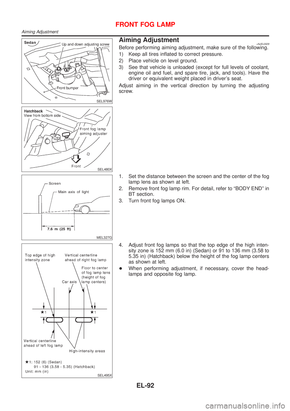
Aiming Adjustment=NJEL0029Before performing aiming adjustment, make sure of the following.
1) Keep all tires inflated to correct pressure.
2) Place vehicle on level ground.
3) See that vehicle is unloaded (except for full levels of coolant,
engine oil and fuel, and spare tire, jack, and tools). Have the
driver or equivalent weight placed in driver's seat.
Adjust aiming in the vertical direction by turning the adjusting
screw.
MEL327G
1. Set the distance between the screen and the center of the fog
lamp lens as shown at left.
2. Remove front fog lamp rim. For detail, refer to ªBODY ENDº in
BT section.
3. Turn front fog lamps ON.
SEL495X
4. Adjust front fog lamps so that the top edge of the high inten-
sity zone is 152 mm (6.0 in) (Sedan) or 91 to 136 mm (3.58 to
5.35 in) (Hatchback) below the height of the fog lamp centers
as shown at left.
+When performing adjustment, if necessary, cover the head-
lamps and opposite fog lamp.
FRONT FOG LAMP
Aiming Adjustment
EL-92