2001 NISSAN ALMERA weight
[x] Cancel search: weightPage 2350 of 2898
combination meter. The indicator blinks when the ignition switch is
in ªOFFº or ªACCº position. Therefore, NATS warns outsiders that
the vehicle is equipped with the anti-theft system.
+When NATS detects trouble, the security indicator lamp lights
up while ignition switch is in ªONº position.
This lighting up indicates that the anti-theft is not functioning,
so prompt service is required.
+When servicing NATS (trouble diagnoses, system initialization
and additional registration of other NATS ignition key IDs),
CONSULT-II hardware and CONSULT-II NATS software is
necessary.
Regarding the procedures of NATS initialization and NATS
ignition key ID registration, refer to CONSULT-II operation
manual, NATS.
Therefore, CONSULT-II NATS software (program card and
operation manual) must be kept strictly confidential to main-
tain the integrity of the anti-theft function.
+When servicing NATS (trouble diagnoses, system initialization
and additional registration of other NATS ignition key IDs), it
may be necessary to re-register original key identification.
Therefore, be sure to receive all keys from vehicle owner. A
maximum of five key IDs can be registered into NATS.
+When failing to start the engine first time using the key of
NATS, start as follows.
a) Leave the ignition key in ªONº position for approximately 5
seconds.
b) Turn ignition key to ªOFFº or ªLOCKº position and wait approxi-
mately 5 seconds.
c) Repeat step 1 and 2 again.
d) Restart the engine while keeping the key separate from any
others on key-chain.
SGI285
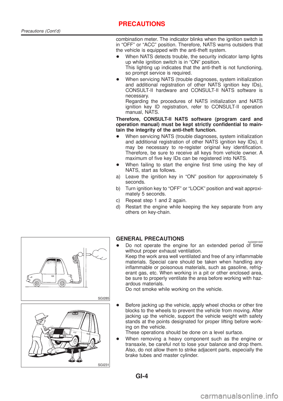
GENERAL PRECAUTIONSNJGI0001S03+Do not operate the engine for an extended period of time
without proper exhaust ventilation.
Keep the work area well ventilated and free of any inflammable
materials. Special care should be taken when handling any
inflammable or poisonous materials, such as gasoline, refrig-
erant gas, etc. When working in a pit or other enclosed area,
be sure to properly ventilate the area before working with haz-
ardous materials.
Do not smoke while working on the vehicle.
SGI231
+Before jacking up the vehicle, apply wheel chocks or other tire
blocks to the wheels to prevent the vehicle from moving. After
jacking up the vehicle, support the vehicle weight with safety
stands at the points designated for proper lifting before work-
ing on the vehicle.
These operations should be done on a level surface.
+When removing a heavy component such as the engine or
transaxle, be careful not to lose your balance and drop them.
Also, do not allow them to strike adjacent parts, especially the
brake tubes and master cylinder.
PRECAUTIONS
Precautions (Cont'd)
GI-4
Page 2363 of 2898
SGI862-A
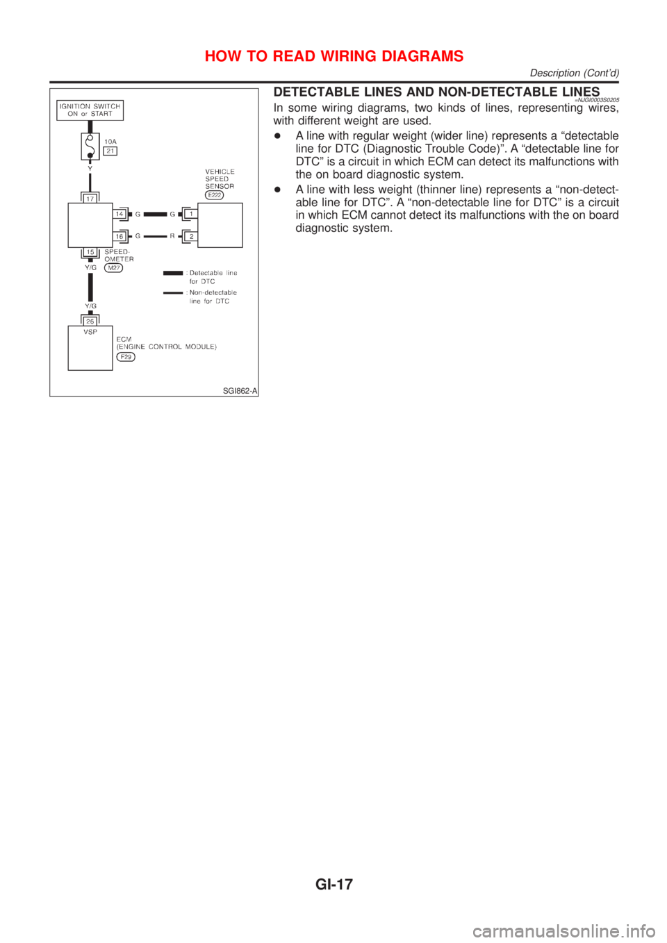
DETECTABLE LINES AND NON-DETECTABLE LINES=NJGI0003S0205In some wiring diagrams, two kinds of lines, representing wires,
with different weight are used.
+A line with regular weight (wider line) represents a ªdetectable
line for DTC (Diagnostic Trouble Code)º. A ªdetectable line for
DTCº is a circuit in which ECM can detect its malfunctions with
the on board diagnostic system.
+A line with less weight (thinner line) represents a ªnon-detect-
able line for DTCº. A ªnon-detectable line for DTCº is a circuit
in which ECM cannot detect its malfunctions with the on board
diagnostic system.
HOW TO READ WIRING DIAGRAMS
Description (Cont'd)
GI-17
Page 2407 of 2898
RHA273D
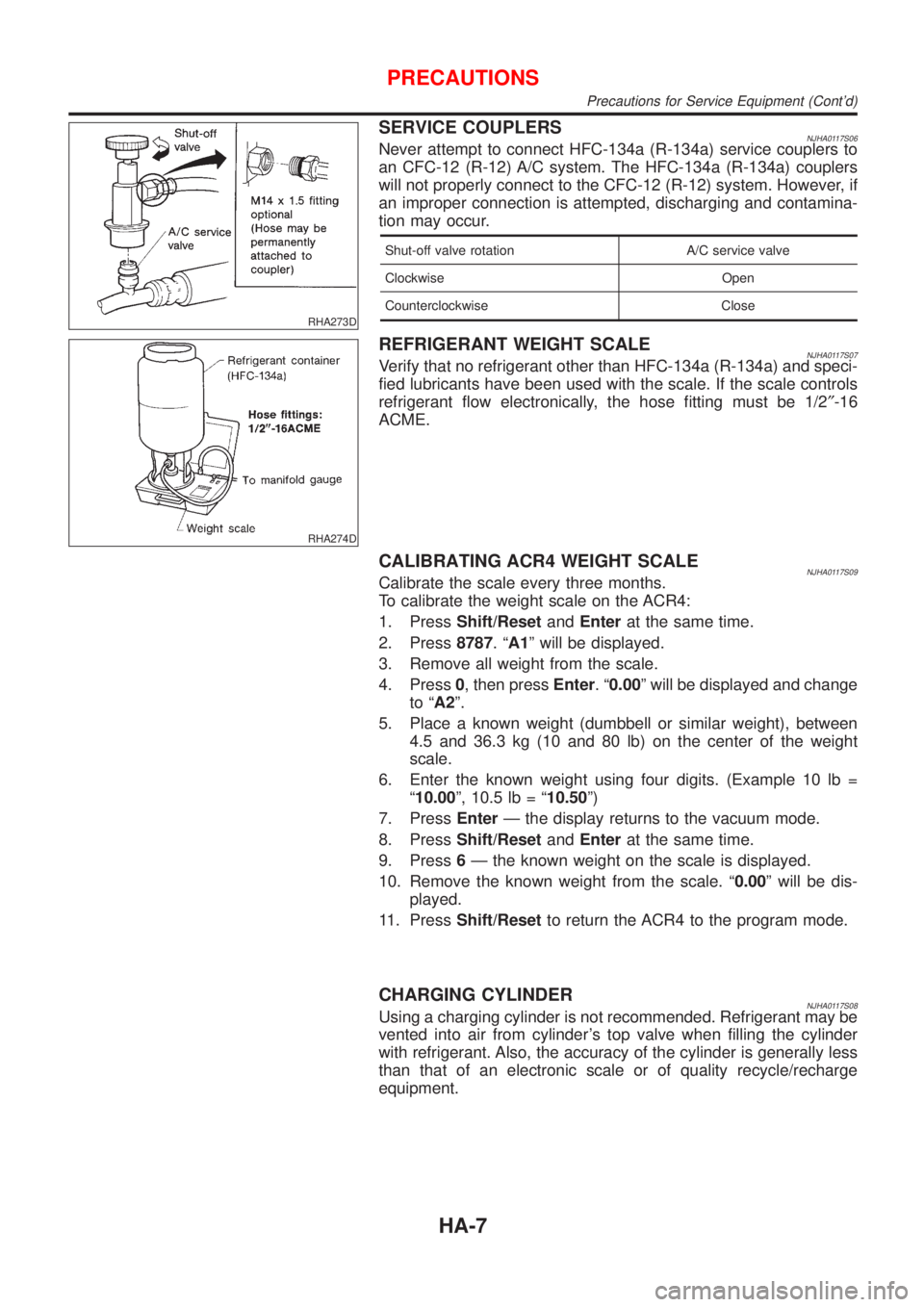
SERVICE COUPLERSNJHA0117S06Never attempt to connect HFC-134a (R-134a) service couplers to
an CFC-12 (R-12) A/C system. The HFC-134a (R-134a) couplers
will not properly connect to the CFC-12 (R-12) system. However, if
an improper connection is attempted, discharging and contamina-
tion may occur.
Shut-off valve rotation A/C service valve
Clockwise Open
Counterclockwise Close
RHA274D
REFRIGERANT WEIGHT SCALENJHA0117S07Verify that no refrigerant other than HFC-134a (R-134a) and speci-
fied lubricants have been used with the scale. If the scale controls
refrigerant flow electronically, the hose fitting must be 1/2²-16
ACME.
CALIBRATING ACR4 WEIGHT SCALENJHA0117S09Calibrate the scale every three months.
To calibrate the weight scale on the ACR4:
1. PressShift/ResetandEnterat the same time.
2. Press8787.ªA1º will be displayed.
3. Remove all weight from the scale.
4. Press0, then pressEnter.ª0.00º will be displayed and change
to ªA2º.
5. Place a known weight (dumbbell or similar weight), between
4.5 and 36.3 kg (10 and 80 lb) on the center of the weight
scale.
6. Enter the known weight using four digits. (Example 10 lb =
ª10.00º, 10.5 lb = ª10.50º)
7. PressEnterÐ the display returns to the vacuum mode.
8. PressShift/ResetandEnterat the same time.
9. Press6Ð the known weight on the scale is displayed.
10. Remove the known weight from the scale. ª0.00º will be dis-
played.
11. PressShift/Resetto return the ACR4 to the program mode.
CHARGING CYLINDERNJHA0117S08Using a charging cylinder is not recommended. Refrigerant may be
vented into air from cylinder's top valve when filling the cylinder
with refrigerant. Also, the accuracy of the cylinder is generally less
than that of an electronic scale or of quality recycle/recharge
equipment.
PRECAUTIONS
Precautions for Service Equipment (Cont'd)
HA-7
Page 2412 of 2898
Tool number
Tool nameDescription
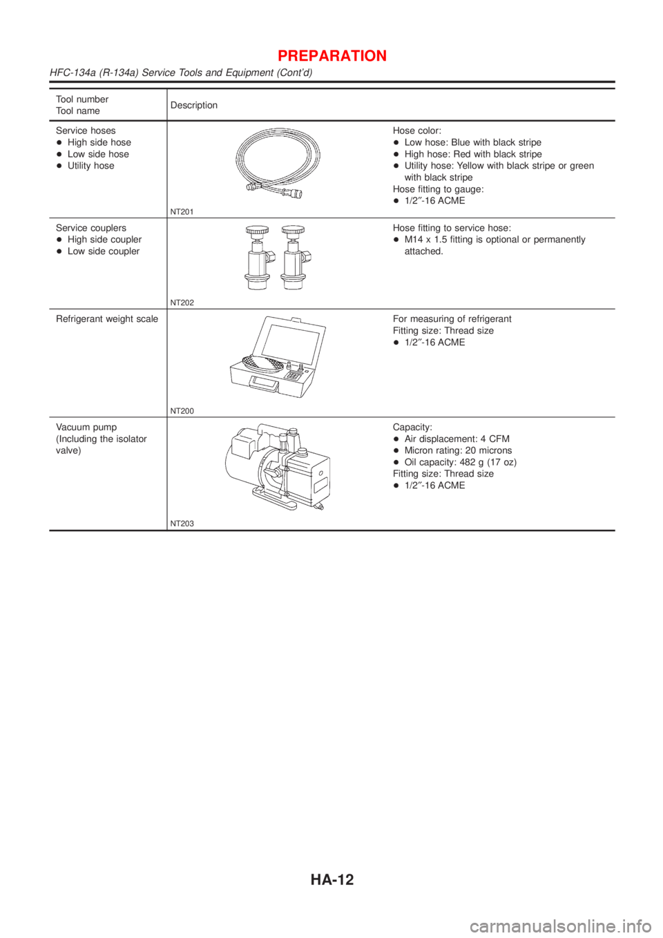
Service hoses
+High side hose
+Low side hose
+Utility hose
NT201
Hose color:
+Low hose: Blue with black stripe
+High hose: Red with black stripe
+Utility hose: Yellow with black stripe or green
with black stripe
Hose fitting to gauge:
+1/2²-16 ACME
Service couplers
+High side coupler
+Low side coupler
NT202
Hose fitting to service hose:
+M14 x 1.5 fitting is optional or permanently
attached.
Refrigerant weight scale
NT200
For measuring of refrigerant
Fitting size: Thread size
+1/2²-16 ACME
Vacuum pump
(Including the isolator
valve)
NT203
Capacity:
+Air displacement: 4 CFM
+Micron rating: 20 microns
+Oil capacity: 482 g (17 oz)
Fitting size: Thread size
+1/2²-16 ACME
PREPARATION
HFC-134a (R-134a) Service Tools and Equipment (Cont'd)
HA-12
Page 2514 of 2898
SLC986AA
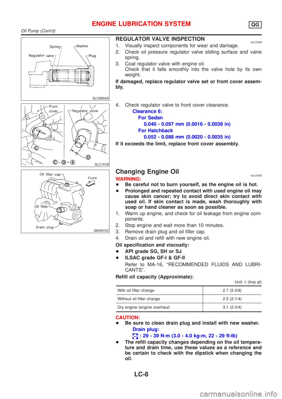
REGULATOR VALVE INSPECTIONNJLC00081. Visually inspect components for wear and damage.
2. Check oil pressure regulator valve sliding surface and valve
spring.
3. Coat regulator valve with engine oil.
Check that it falls smoothly into the valve hole by its own
weight.
If damaged, replace regulator valve set or front cover assem-
bly.
SLC101B
4. Check regulator valve to front cover clearance.
Clearance 6:
For Sedan
0.040 - 0.097 mm (0.0016 - 0.0038 in)
For Hatchback
0.052 - 0.088 mm (0.0020 - 0.0035 in)
If it exceeds the limit, replace front cover assembly.
SMA915C
Changing Engine OilNJLC0035WARNING:
+Be careful not to burn yourself, as the engine oil is hot.
+Prolonged and repeated contact with used engine oil may
cause skin cancer; try to avoid direct skin contact with
used oil. If skin contact is made, wash thoroughly with
soap or hand cleaner as soon as possible.
1. Warm up engine, and check for oil leakage from engine com-
ponents.
2. Stop engine and wait more than 10 minutes.
3. Remove drain plug and oil filler cap.
4. Drain oil and refill with new engine oil.
Oil specification and viscosity:
+API grade SG, SH or SJ
+ILSAC grade GF-I & GF-II
Refer to MA-16, ªRECOMMENDED FLUIDS AND LUBRI-
CANTSº.
Refill oil capacity (Approximate):
Unit:!(Imp qt)
With oil filter change 2.7 (2-3/8)
Without oil filter change 2.5 (2-1/4)
Dry engine (engine overhaul) 3.1 (2-3/4)
CAUTION:
+Be sure to clean drain plug and install with new washer.
Drain plug:
: 29 - 39 N´m (3.0 - 4.0 kg-m, 22 - 29 ft-lb)
+The refill capacity changes depending on the oil tempera-
ture and drain time, use these values as a reference and
be certain to check with the dipstick when changing the
oil.
ENGINE LUBRICATION SYSTEMQG
Oil Pump (Cont'd)
LC-8
Page 2536 of 2898
JLC356B
JLC338B
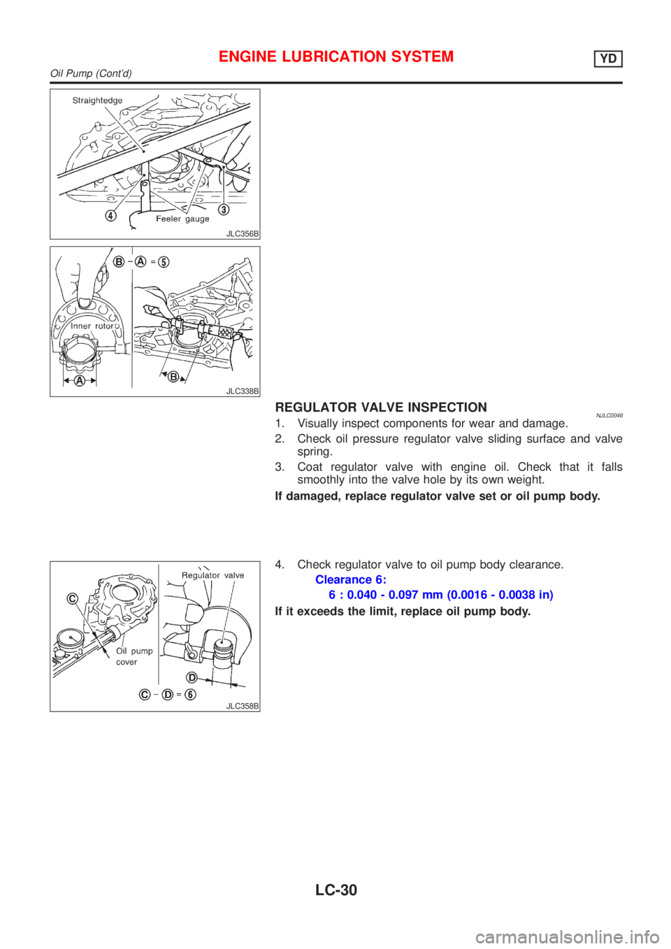
REGULATOR VALVE INSPECTIONNJLC00461. Visually inspect components for wear and damage.
2. Check oil pressure regulator valve sliding surface and valve
spring.
3. Coat regulator valve with engine oil. Check that it falls
smoothly into the valve hole by its own weight.
If damaged, replace regulator valve set or oil pump body.
JLC358B
4. Check regulator valve to oil pump body clearance.
Clearance 6:
6 : 0.040 - 0.097 mm (0.0016 - 0.0038 in)
If it exceeds the limit, replace oil pump body.
ENGINE LUBRICATION SYSTEMYD
Oil Pump (Cont'd)
LC-30
Page 2884 of 2898
SFA449BB
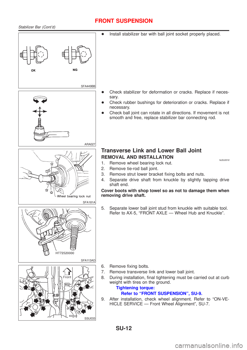
+Install stabilizer bar with ball joint socket properly placed.
ARA027
+Check stabilizer for deformation or cracks. Replace if neces-
sary.
+Check rubber bushings for deterioration or cracks. Replace if
necessary.
+Check ball joint can rotate in all directions. If movement is not
smooth and free, replace stabilizer bar connecting rod.
SFA181A
Transverse Link and Lower Ball Joint
REMOVAL AND INSTALLATIONNJSU00181. Remove wheel bearing lock nut.
2. Remove tie-rod ball joint.
3. Remove strut lower bracket fixing bolts and nuts.
4. Separate drive shaft from knuckle by slightly tapping drive
shaft end.
Cover boots with shop towel so as not to damage them when
removing drive shaft.
SFA113AD
5. Separate lower ball joint stud from knuckle with suitable tool.
Refer to AX-5, ªFRONT AXLE Ð Wheel Hub and Knuckleº.
SSU033
6. Remove fixing bolts.
7. Remove transverse link and lower ball joint.
8. During installation, final tightening must be carried out at curb
weight with tires on the ground.
Tightening torque:
Refer to ªFRONT SUSPENSIONº, SU-9.
9. After installation, check wheel alignment. Refer to ªON-VE-
HICLE SERVICE Ð Front Wheel Alignmentº, SU-7.
FRONT SUSPENSION
Stabilizer Bar (Cont'd)
SU-12