2001 NISSAN ALMERA AUX
[x] Cancel search: AUXPage 34 of 2898

TCM FUNCTION=NJAT0014S03The function of the TCM is to:
+Receive input signals sent from various switches and sensors.
+Determine required line pressure, shifting point, lock-up operation, and engine brake operation.
+Send required output signals to the respective solenoids.
INPUT/OUTPUT SIGNAL OF TCMNJAT0014S04
Sensors, switches and solenoid
valvesFunction
InputPNP switch Detects select lever position and sends a signal to TCM.
Throttle position sensor Detects throttle valve position and sends a signal to TCM.
Closed throttle position switch Detects throttle valve's fully-closed position and sends a signal to TCM.
Wide open throttle position switchDetects a throttle valve position of greater than 1/2 of full throttle and sends
a signal to TCM.
Engine speed signal From ECM.
A/T fluid temperature sensor Detects transmission fluid temperature and sends a signal to TCM.
Revolution sensor Detects output shaft rpm and sends a signal to TCM.
Vehicle speed sensorUsed as an auxiliary vehicle speed sensor. Sends a signal when revolution
sensor (installed on transmission) malfunctions.
Overdrive control switchSends a signal, which prohibits a shift to ªD
4º (overdrive) position, to the
TCM.
Stop lamp switch Releases lock-up system when depressing pedal in lock-up condition.
OutputShift solenoid valve A/BSelects shifting point suited to driving conditions in relation to a signal sent
from TCM.
Line pressure solenoid valveRegulates (or decreases) line pressure suited to driving conditions in rela-
tion to a signal sent from TCM.
Torque converter clutch solenoid
valveRegulates (or decreases) lock-up pressure suited to driving conditions in
relation to a signal sent from TCM.
Overrun clutch solenoid valveControls an ªengine brakeº effect suited to driving conditions in relation to a
signal sent from TCM.
O/D OFF indicator lamp Shows TCM faults, when A/T control components malfunction.
Control MechanismNJAT0015LINE PRESSURE CONTROLNJAT0015S01TCM has various line pressure control characteristics to match the
driving conditions.
An ON-OFF duty signal is sent to the line pressure solenoid valve
based on TCM characteristics.
Hydraulic pressure on the clutch and brake is electronically con-
trolled through the line pressure solenoid valve to accommodate
engine torque. This results in smooth shift operation.
OVERALL SYSTEM
Control System (Cont'd)
AT-32
Page 133 of 2898
SAT059K
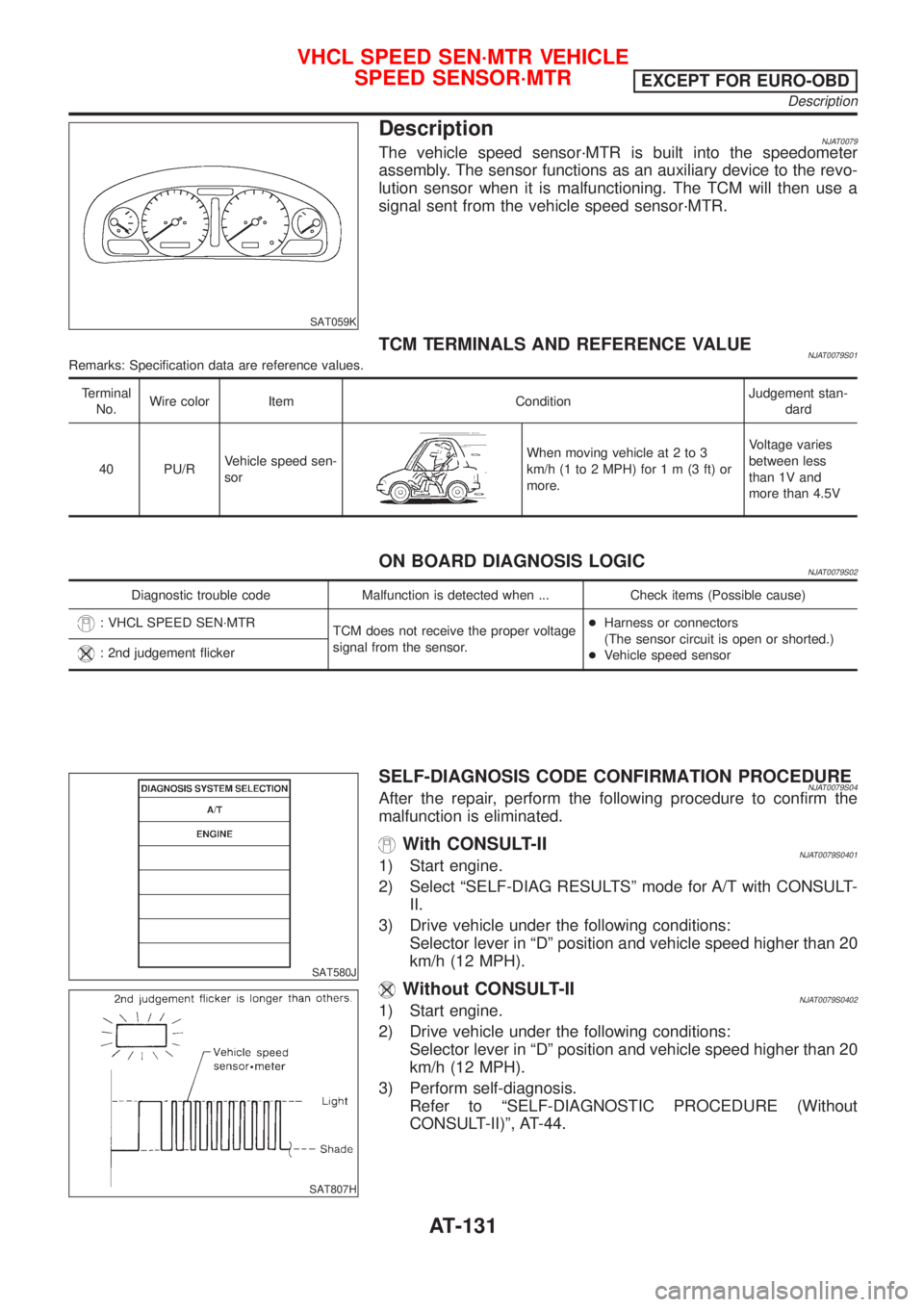
DescriptionNJAT0079The vehicle speed sensor´MTR is built into the speedometer
assembly. The sensor functions as an auxiliary device to the revo-
lution sensor when it is malfunctioning. The TCM will then use a
signal sent from the vehicle speed sensor´MTR.
TCM TERMINALS AND REFERENCE VALUENJAT0079S01Remarks: Specification data are reference values.
Terminal
No.Wire color Item ConditionJudgement stan-
dard
40 PU/RVehicle speed sen-
sor
When moving vehicle at 2 to 3
km/h (1 to 2 MPH) for1m(3ft)or
more.Voltage varies
between less
than 1V and
more than 4.5V
ON BOARD DIAGNOSIS LOGICNJAT0079S02
Diagnostic trouble code Malfunction is detected when ... Check items (Possible cause)
: VHCL SPEED SEN´MTR
TCM does not receive the proper voltage
signal from the sensor.+Harness or connectors
(The sensor circuit is open or shorted.)
+Vehicle speed sensor
: 2nd judgement flicker
SAT580J
SAT807H
SELF-DIAGNOSIS CODE CONFIRMATION PROCEDURENJAT0079S04After the repair, perform the following procedure to confirm the
malfunction is eliminated.
With CONSULT-IINJAT0079S04011) Start engine.
2) Select ªSELF-DIAG RESULTSº mode for A/T with CONSULT-
II.
3) Drive vehicle under the following conditions:
Selector lever in ªDº position and vehicle speed higher than 20
km/h (12 MPH).
Without CONSULT-IINJAT0079S04021) Start engine.
2) Drive vehicle under the following conditions:
Selector lever in ªDº position and vehicle speed higher than 20
km/h (12 MPH).
3) Perform self-diagnosis.
Refer to ªSELF-DIAGNOSTIC PROCEDURE (Without
CONSULT-II)º, AT-44.
VHCL SPEED SEN´MTR VEHICLE
SPEED SENSOR´MTR
EXCEPT FOR EURO-OBD
Description
AT-131
Page 283 of 2898

SAT070K
DescriptionNJAT0323The vehicle speed sensor´MTR is built into the speedometer
assembly. The sensor functions as an auxiliary device to the revo-
lution sensor when it is malfunctioning. The TCM will then use a
signal sent from the vehicle speed sensor´MTR.
TCM TERMINALS AND REFERENCE VALUENJAT0323S01Remarks: Specification data are reference values.
Terminal
No.Wire color Item ConditionJudgement stan-
dard
40 PU/RVehicle speed
sensor
When moving vehicle at 2 to 3 km/h
(1 to 2 MPH) for1m(3ft)ormore.Voltage varies
between less
than 1V and more
than 4.5V
ON BOARD DIAGNOSIS LOGICNJAT0323S02
Diagnostic trouble code Malfunction is detected when ... Check items (Possible cause)
: VHCL SPEED SEN´MTR
TCM does not receive the proper voltage
signal from the sensor.+Harness or connectors
(The sensor circuit is open or shorted.)
+Vehicle speed sensor
: 2nd judgement flicker
DTC VHCL SPEED SEN´MTR VEHICLE SPEED SENSOR´MTREURO-OBD
Description
AT-281
Page 728 of 2898
Diagnostic Procedure ..............................................332
Component Inspection .............................................334
DTC P0340 CAMSHAFT POSITION SENSOR
(CMPS) (PHASE).........................................................335
Component Description ...........................................335
ECM Terminals and Reference Value .....................335
On Board Diagnosis Logic.......................................336
DTC Confirmation Procedure ..................................336
Wiring Diagram ........................................................337
Diagnostic Procedure ..............................................339
Component Inspection .............................................342
DTC P0400 EGR FUNCTION (CLOSED) (WHERE
FITTED)........................................................................343
Description ...............................................................343
CONSULT-II Reference Value in Data Monitor
Mode ........................................................................344
ECM Terminals and Reference Value .....................344
On Board Diagnosis Logic.......................................344
DTC Confirmation Procedure ..................................345
Wiring Diagram ........................................................347
Diagnostic Procedure ..............................................349
Component Inspection .............................................351
DTC P0403 EGR VOLUME CONTROL VALVE
(CIRCUIT).....................................................................352
Description ...............................................................352
CONSULT-II Reference Value in Data Monitor
Mode ........................................................................353
ECM Terminals and Reference Value .....................353
On Board Diagnosis Logic.......................................353
DTC Confirmation Procedure ..................................353
Wiring Diagram ........................................................355
Diagnostic Procedure ..............................................357
Component Inspection .............................................358
DTC P0420 THREE WAY CATALYST FUNCTION...359
On Board Diagnosis Logic.......................................359
DTC Confirmation Procedure ..................................359
Overall Function Check ...........................................360
Diagnostic Procedure ..............................................360
DTC P0443 EVAP CANISTER PURGE VOLUME
CONTROL SOLENOID VALVE (CIRCUIT).................364
Description ...............................................................364
CONSULT-II Reference Value in Data Monitor
Mode ........................................................................364
ECM Terminals and Reference Value .....................365
On Board Diagnosis Logic.......................................365
DTC Confirmation Procedure ..................................365
Wiring Diagram ........................................................366
Diagnostic Procedure ..............................................368
Component Inspection .............................................369
DTC P0500 VEHICLE SPEED SENSOR (VSS).........370
Component Description ...........................................370
ECM Terminals and Reference Value .....................370On Board Diagnosis Logic.......................................370
DTC Confirmation Procedure ..................................370
Wiring Diagram ........................................................372
Diagnostic Procedure ..............................................375
DTC P0505 IDLE AIR CONTROL VALVE (IACV) -
AUXILIARY AIR CONTROL (AAC) VALVE...............376
Description ...............................................................376
CONSULT-II Reference Value in Data Monitor
Mode ........................................................................377
ECM Terminals and Reference Value .....................377
On Board Diagnosis Logic.......................................377
DTC Confirmation Procedure ..................................377
Wiring Diagram ........................................................378
Diagnostic Procedure ..............................................380
Component Inspection .............................................384
DTC P0510 CLOSED THROTTLE POSITION
SWITCH (WHERE FITTED).........................................385
Component Description ...........................................385
CONSULT-II Reference Value in Data Monitor
Mode ........................................................................385
ECM Terminals and Reference Value .....................385
On Board Diagnosis Logic.......................................385
DTC Confirmation Procedure ..................................385
Overall Function Check ...........................................386
Wiring Diagram ........................................................387
Diagnostic Procedure ..............................................388
Component Inspection .............................................389
DTC P0605 ECM.........................................................391
Component Description ...........................................391
On Board Diagnosis Logic.......................................391
DTC Confirmation Procedure ..................................391
Diagnostic Procedure ..............................................392
D T C P 1111INTAKE VALVE TIMING CONTROL
SOLENOID VALVE......................................................393
Component Description ...........................................393
Operation .................................................................393
CONSULT-II Reference Value in Data Monitor
Mode ........................................................................393
ECM Terminals and Reference Value .....................393
On Board Diagnosis Logic.......................................393
DTC Confirmation Procedure ..................................394
Wiring Diagram ........................................................395
Diagnostic Procedure ..............................................397
Component Inspection .............................................398
DTC P1131 SWIRL CONTROL VALVE SOLENOID
VALVE (CIRCUIT) (WHERE FITTED).........................399
Description ...............................................................399
CONSULT-II Reference Value in Data Monitor
Mode ........................................................................399
ECM Terminals and Reference Value .....................400
Component Description ...........................................400
On Board Diagnosis Logic.......................................400
CONTENTS(Cont'd)
EC-4
Page 730 of 2898
Diagnostic Procedure ..............................................487
Component Inspection .............................................490
EGR VOLUME CONTROL SYSTEM (WHERE
FITTED)........................................................................491
Description ...............................................................491
CONSULT-II Reference Value in Data Monitor
Mode ........................................................................492
ECM Terminals and Reference Value .....................493
Wiring Diagram ........................................................494
Diagnostic Procedure ..............................................496
Component Inspection .............................................501
EVAP CANISTER PURGE VOLUME CONTROL
SOLENOID VALVE......................................................503
Description ...............................................................503
CONSULT-II Reference Value in Data Monitor
Mode ........................................................................503
ECM Terminals and Reference Value .....................504
Wiring Diagram ........................................................505
Diagnostic Procedure ..............................................507
Component Inspection .............................................510
IDLE AIR CONTROL VALVE (IACV) - AUXILIARY
AIR CONTROL............................................................ 511
Description ............................................................... 511
CONSULT-II Reference Value in Data Monitor
Mode ........................................................................512
ECM Terminals and Reference Value .....................512
Wiring Diagram ........................................................513
Diagnostic Procedure ..............................................515
Component Inspection .............................................519
CLOSED THROTTLE POSITION SWITCH
(WHERE FITTED)........................................................520
Component Description ...........................................520
ECM Terminals and Reference Value .....................520
Wiring Diagram ........................................................521
Diagnostic Procedure ..............................................522
Component Inspection .............................................525
INTAKE VALVE TIMING CONTROL SOLENOID
VALVE..........................................................................526
Component Description ...........................................526
Operation .................................................................526
CONSULT-II Reference Value in Data Monitor
Mode ........................................................................526
ECM Terminals and Reference Value .....................526
Wiring Diagram ........................................................527
Diagnostic Procedure ..............................................529
Component Inspection .............................................531
A/T COMMUNICATION LINE......................................532
System Description ..................................................532
Wiring Diagram ........................................................533
Diagnostic Procedure ..............................................534
PARK/NEUTRAL POSITION (PNP) SWITCH............536
Component Description ...........................................536CONSULT-II Reference Value in Data Monitor
Mode ........................................................................536
ECM Terminals and Reference Value .....................536
Wiring Diagram ........................................................537
Diagnostic Procedure ..............................................538
INJECTOR...................................................................541
Component Description ...........................................541
CONSULT-II Reference Value in Data Monitor
Mode ........................................................................541
ECM Terminals and Reference Value .....................541
Wiring Diagram ........................................................542
Diagnostic Procedure ..............................................544
Component Inspection .............................................546
IGNITION SIGNAL.......................................................547
Component Description ...........................................547
CONSULT-II Reference Value in Data Monitor
Mode ........................................................................547
ECM Terminals and Reference Value .....................547
Wiring Diagram ........................................................548
Diagnostic Procedure ..............................................551
Component Inspection .............................................555
START SIGNAL...........................................................557
CONSULT-II Reference Value in Data Monitor
Mode ........................................................................557
ECM Terminals and Reference Value .....................557
Wiring Diagram ........................................................558
Diagnostic Procedure ..............................................559
FUEL PUMP.................................................................561
System Description ..................................................561
Component Description ...........................................561
CONSULT-II Reference Value in Data Monitor
Mode ........................................................................561
ECM Terminals and Reference Value .....................562
Wiring Diagram ........................................................563
Diagnostic Procedure ..............................................564
Component Inspection .............................................566
POWER STEERING OIL PRESSURE SWITCH.........567
Component Description ...........................................567
CONSULT-II Reference Value in Data Monitor
Mode ........................................................................567
ECM Terminals and Reference Value .....................567
Wiring Diagram ........................................................568
Diagnostic Procedure ..............................................569
Component Inspection .............................................570
REFRIGERANT PRESSURE SENSOR......................572
Description ...............................................................572
ECM Terminals and Reference Value .....................572
Wiring Diagram ........................................................573
Diagnostic Procedure ..............................................575
ELECTRICAL LOAD SIGNAL.....................................578
CONSULT-II Reference Value in Data Monitor
Mode ........................................................................578
CONTENTS(Cont'd)
EC-6
Page 1100 of 2898
DescriptionNJEC0279SYSTEM DESCRIPTIONNJEC0279S01
Sensor Input Signal to ECMECM func-
tionActuator
Crankshaft position sensor (POS) Engine speed
Idle air
controlIACV-AAC valve Camshaft position sensor (PHASE) Engine speed and cylinder number
Engine coolant temperature sensor Engine coolant temperature
Ignition switch Start signal
Throttle position sensor Throttle position
PNP switch Park/Neutral position
Air conditioner switch Air conditioner operation
Power steering oil pressure switch Power steering load signal
Battery Battery voltage
Vehicle speed sensor Vehicle speed
Cooling fan Cooling fan operation
Electrical load Electrical load signal
This system automatically controls engine idle speed to a specified
level. Idle speed is controlled through fine adjustment of the
amount of air which by-passes the throttle valve via IACV-AAC
valve. The IACV-AAC valve changes the opening of the air by-pass
passage to control the amount of auxiliary air. This valve is actu-
ated by a step motor built into the valve, which moves the valve in
the axial direction in steps corresponding to the ECM output sig-
nals. One step of IACV-AAC valve movement causes the respec-
tive opening of the air by-pass passage. (i.e. when the step
advances, the opening is enlarged.) The opening of the valve is
varied to allow for optimum control of the engine idling speed. The
crankshaft position sensor (POS) detects the actual engine speed
and sends a signal to the ECM. The ECM then controls the step
position of the IACV-AAC valve so that engine speed coincides with
the target value memorized in ECM. The target engine speed is the
lowest speed at which the engine can operate steadily. The opti-
mum value stored in the ECM is determined by taking into consid-
eration various engine conditions, such as during warm up,
deceleration, and engine load (air conditioner, power steering, cool-
ing fan operation and electrical load).
SEF937W
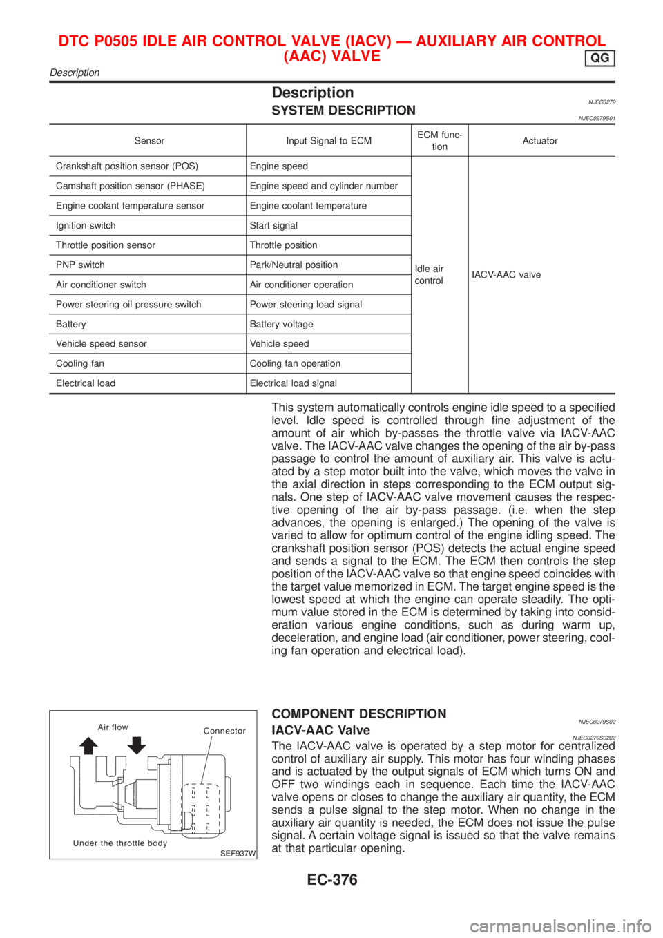
COMPONENT DESCRIPTIONNJEC0279S02IACV-AAC ValveNJEC0279S0202The IACV-AAC valve is operated by a step motor for centralized
control of auxiliary air supply. This motor has four winding phases
and is actuated by the output signals of ECM which turns ON and
OFF two windings each in sequence. Each time the IACV-AAC
valve opens or closes to change the auxiliary air quantity, the ECM
sends a pulse signal to the step motor. When no change in the
auxiliary air quantity is needed, the ECM does not issue the pulse
signal. A certain voltage signal is issued so that the valve remains
at that particular opening.
DTC P0505 IDLE AIR CONTROL VALVE (IACV) Ð AUXILIARY AIR CONTROL
(AAC) VALVE
QG
Description
EC-376
Page 1101 of 2898
CONSULT-II Reference Value in Data Monitor
Mode
NJEC0280
MONITOR ITEM CONDITION SPECIFICATION
IACV-AAC/V+Engine: After warming up
+Air conditioner switch: OFF
+Shift lever: ªNº
+No-loadIdle 5 - 25 steps
2,000 rpm Ð
ECM Terminals and Reference ValueNJEC0281Specification data are reference values and are measured between each terminal and ground.
CAUTION:
Do not use ECM ground terminals when measuring input/output voltage. Doing so may result in dam-
age to the ECM's transistor. Use a ground other than ECM terminals, such as the ground.
TER-
MINAL
NO.WIRE
COLORITEM CONDITION DATA (DC Voltage)
6
7
15
16BR
LG
P
ORIACV-AAC valve[Engine is running]
+Warm-up condition
+Idle speed0.1 - 14V
On Board Diagnosis LogicNJEC0282
DTC No. Malfunction is detected when ... Check Items (Possible Cause)
P0505
0505+An improper voltage signal is sent to ECM through the
valve.+Harness or connectors
(The IACV-AAC valve circuit is open.)
+IACV-AAC valve
SEF058Y
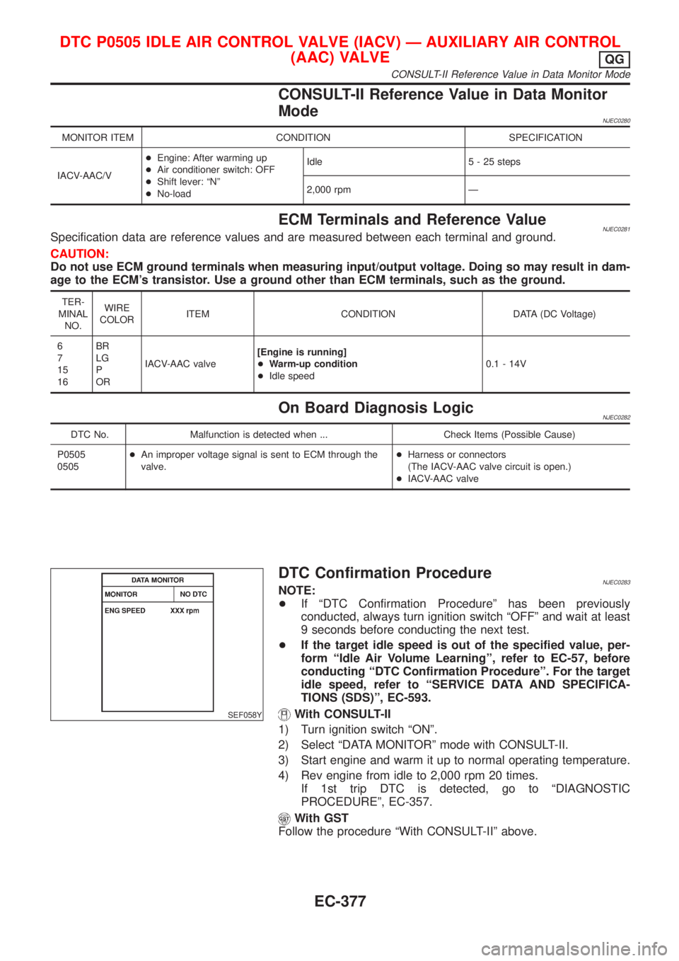
DTC Confirmation ProcedureNJEC0283NOTE:
+If ªDTC Confirmation Procedureº has been previously
conducted, always turn ignition switch ªOFFº and wait at least
9 seconds before conducting the next test.
+If the target idle speed is out of the specified value, per-
form ªIdle Air Volume Learningº, refer to EC-57, before
conducting ªDTC Confirmation Procedureº. For the target
idle speed, refer to ªSERVICE DATA AND SPECIFICA-
TIONS (SDS)º, EC-593.
With CONSULT-II
1) Turn ignition switch ªONº.
2) Select ªDATA MONITORº mode with CONSULT-II.
3) Start engine and warm it up to normal operating temperature.
4) Rev engine from idle to 2,000 rpm 20 times.
If 1st trip DTC is detected, go to ªDIAGNOSTIC
PROCEDUREº, EC-357.
With GST
Follow the procedure ªWith CONSULT-IIº above.
DTC P0505 IDLE AIR CONTROL VALVE (IACV) Ð AUXILIARY AIR CONTROL
(AAC) VALVE
QG
CONSULT-II Reference Value in Data Monitor Mode
EC-377
Page 1102 of 2898
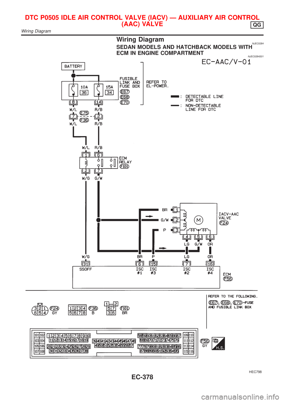
Wiring DiagramNJEC0284SEDAN MODELS AND HATCHBACK MODELS WITH
ECM IN ENGINE COMPARTMENT
NJEC0284S01
HEC798
DTC P0505 IDLE AIR CONTROL VALVE (IACV) Ð AUXILIARY AIR CONTROL
(AAC) VALVE
QG
Wiring Diagram
EC-378