Page 1237 of 2898
Wiring DiagramNJEC1761SEDAN MODELS AND HATCHBACK MODELS WITH ECM IN ENGINE COMPARTMENTNJEC1761S01
HEC910
IDLE AIR CONTROL VALVE (IACV) Ð AUXILIARY AIR CONTROL
(AAC) VALVE
QG
Wiring Diagram
EC-513
Page 1238 of 2898
HATCHBACK MODELS WITH ECM IN CABINNJEC1761S02
HEC982
IDLE AIR CONTROL VALVE (IACV) Ð AUXILIARY AIR CONTROL
(AAC) VALVE
QG
Wiring Diagram (Cont'd)
EC-514
Page 1239 of 2898
Diagnostic ProcedureNJEC1762
1 CHECK OVERALL FUNCTION
1. Turn ignition switch ªOFFº.
2. Read the voltage signal between ECM terminals 6, 7, 15, 16 (IACV-AAC valve signal) and ground with an oscilloscope.
3. Turn ignition switch ªONº, wait at least 5 seconds and then ªOFFº.
4. Verify that the oscilloscope screen shows the signal wave as shown below at least once every 10 seconds after turning
ignition switch ªOFFº.
SEF756Z
OK or NG
OK©INSPECTION END
NG©GO TO 2.
2 CHECK POWER SUPPLY
1. Turn ignition switch ªOFFº.
2. Disconnect IACV-AAC valve harness connector.
NEF316A
3. Turn ignition switch ªONº.
4. Check voltage between terminal 2, 5 and ground with CONSULT-II or tester.
SEF343X
OK or NG
OK©GO TO 4.
NG©GO TO 3.
IDLE AIR CONTROL VALVE (IACV) Ð AUXILIARY AIR CONTROL
(AAC) VALVE
QG
Diagnostic Procedure
EC-515
Page 1240 of 2898

3 DETECT MALFUNCTIONING PART
Check the following.
+15A fuse
+Harness connectors E75, F36 (If so equipped)
+Harness for open or short between fuse and ECM relay
+ECM relay
+Harness for open or short between IACV-AAC and ECM relay.
©Repair harness or connectors, or replace fuse or ECM relay.
4 CHECK OUTPUT SIGNAL CIRCUIT
1. Turn ignition switch ªOFFº.
2. Disconnect ECM harness connector.
3. Check harness continuity between
ECM terminal 6 and IACV-AAC valve terminal 1,
ECM terminal 7 and IACV-AAC valve terminal 4,
ECM terminal 15 and IACV-AAC valve terminal 3,
ECM terminal 16 and IACV-AAC valve terminal 6.
Refer to wiring diagram.
Continuity should exist.
4. Also check harness for short to ground and short to power.
OK or NG
OK©GO TO 5.
NG©Repair open circuit or short to ground or short to power in harness or connectors.
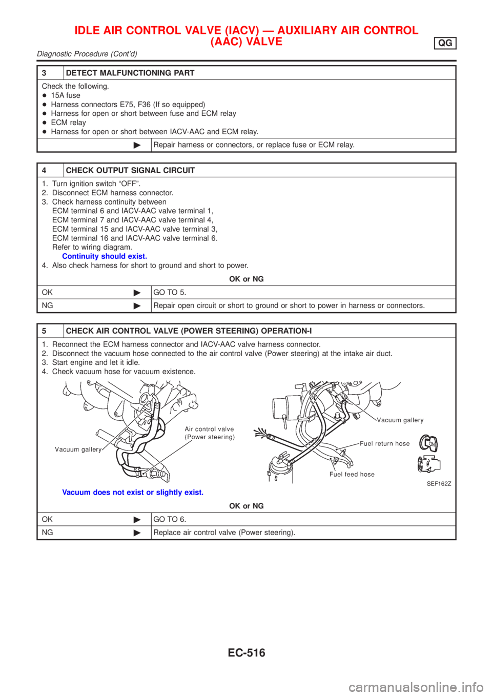
5 CHECK AIR CONTROL VALVE (POWER STEERING) OPERATION-I
1. Reconnect the ECM harness connector and IACV-AAC valve harness connector.
2. Disconnect the vacuum hose connected to the air control valve (Power steering) at the intake air duct.
3. Start engine and let it idle.
4. Check vacuum hose for vacuum existence.
SEF162Z
Vacuum does not exist or slightly exist.
OK or NG
OK©GO TO 6.
NG©Replace air control valve (Power steering).
IDLE AIR CONTROL VALVE (IACV) Ð AUXILIARY AIR CONTROL
(AAC) VALVE
QG
Diagnostic Procedure (Cont'd)
EC-516
Page 1241 of 2898
6 CHECK AIR CONTROL VALVE (POWER STEERING) OPERATION-II
Check the vacuum hose for vacuum existence when steering wheel is turned.
SEF162Z
Vacuum should exist.
OK or NG
OK©GO TO 9.
NG©GO TO 7.
7 CHECK VACUUM PORT
1. Stop engine.
2. Disconnect the vacuum hose connected to the air control valve (Power steering) at the vacuum port.
3. Blow air into vacuum port.
4. Check that air flows freely.
SEF924Y
OK or NG
OK©GO TO 8.
NG©Repair or clean vacuum port.
IDLE AIR CONTROL VALVE (IACV) Ð AUXILIARY AIR CONTROL
(AAC) VALVE
QG
Diagnostic Procedure (Cont'd)
EC-517
Page 1242 of 2898

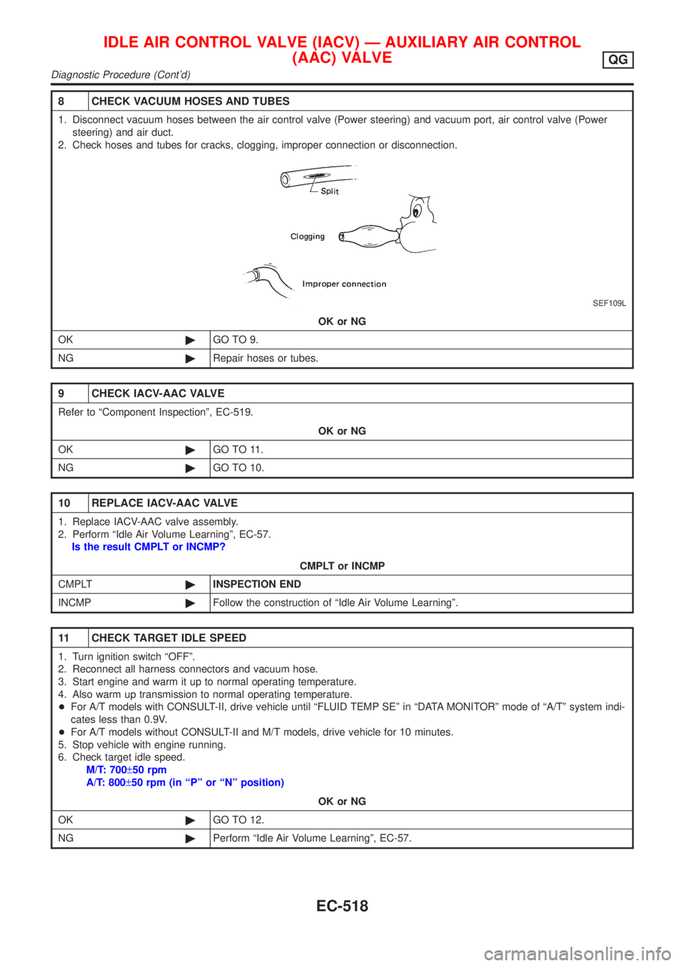
8 CHECK VACUUM HOSES AND TUBES
1. Disconnect vacuum hoses between the air control valve (Power steering) and vacuum port, air control valve (Power
steering) and air duct.
2. Check hoses and tubes for cracks, clogging, improper connection or disconnection.
SEF109L
OK or NG
OK©GO TO 9.
NG©Repair hoses or tubes.
9 CHECK IACV-AAC VALVE
Refer to ªComponent Inspectionº, EC-519.
OK or NG
OK©GO TO 11.
NG©GO TO 10.
10 REPLACE IACV-AAC VALVE
1. Replace IACV-AAC valve assembly.
2. Perform ªIdle Air Volume Learningº, EC-57.
Is the result CMPLT or INCMP?
CMPLT or INCMP
CMPLT©INSPECTION END
INCMP©Follow the construction of ªIdle Air Volume Learningº.
11 CHECK TARGET IDLE SPEED
1. Turn ignition switch ªOFFº.
2. Reconnect all harness connectors and vacuum hose.
3. Start engine and warm it up to normal operating temperature.
4. Also warm up transmission to normal operating temperature.
+For A/T models with CONSULT-II, drive vehicle until ªFLUID TEMP SEº in ªDATA MONITORº mode of ªA/Tº system indi-
cates less than 0.9V.
+For A/T models without CONSULT-II and M/T models, drive vehicle for 10 minutes.
5. Stop vehicle with engine running.
6. Check target idle speed.
M/T: 700±50 rpm
A/T: 800±50 rpm (in ªPº or ªNº position)
OK or NG
OK©GO TO 12.
NG©Perform ªIdle Air Volume Learningº, EC-57.
IDLE AIR CONTROL VALVE (IACV) Ð AUXILIARY AIR CONTROL
(AAC) VALVE
QG
Diagnostic Procedure (Cont'd)
EC-518
Page 1243 of 2898
12 CHECK INTERMITTENT INCIDENT
Perform ªTROUBLE DIAGNOSIS FOR INTERMITTENT INCIDENTº, EC-177.
©INSPECTION END
SEF605Y
SEF089X
Component InspectionNJEC1763IACV-AAC VALVENJEC1763S011) Disconnect IACV-AAC valve harness connector.
2) Check IACV-AAC valve resistance.
Condition Resistance
Terminal 2 and terminals 1, 3
20-24W[at 20ÉC (68ÉF)]
Terminal 5 and terminals 4, 6
3) Reconnect IACV-AAC valve harness connector.
4) Remove idle air adjusting unit assembly (IACV-AAC valve is
built-in) from engine.
(The IACV-AAC valve harness connector should remain con-
nected.)
5) Turn ignition switch ªONº and ªOFFº, and ensure the IACV-
AAC valve shaft smoothly moves forward and backward,
according to the ignition switch position.
If NG, replace the IACV-AAC valve.
IDLE AIR CONTROL VALVE (IACV) Ð AUXILIARY AIR CONTROL
(AAC) VALVE
QG
Diagnostic Procedure (Cont'd)
EC-519
Page 1839 of 2898
Inspection=NJEL0221AUDIO UNITNJEL0221S01All voltage inspections are made with:
+Ignition switch ON or ACC
+Audio unit ON
+Audio unit connected (If audio unit is removed for inspection, supply a ground to the case using a jumper
wire.)
ANTENNANJEL0221S02Using a jumper wire, clip an auxiliary ground between antenna and body.
+If reception improves, check antenna ground (at body surface).
+If reception does not improve, check main feeder cable for short circuit or open circuit.
AUDIO
Inspection
EL-281