2001 NISSAN ALMERA AUX
[x] Cancel search: AUXPage 2272 of 2898
crankshaft position sensor (TDC sensor) from the assem-
bly.
+Always pay extra attention not to damage edge of crank-
shaft position sensor (TDC sensor) or ring gear teeth.
REMOVALNJEM0069S011. Remove engine undercover, and hood for hoisting.
2. Drain coolant from both cylinder block and radiator. Refer to
LC-44, ªChanging Engine Coolantº.
3. Remove the following parts:
+Battery
+RH and LH front wheels
+RH and LH splash covers (combined with undercover)
+Auxiliary belts
+Alternator
+Alternator brackets
+Radiator and cooling fan
+Engine cover
+Air ducts and air cleaner case
LH side of engine room:
4. Disconnect all harnesses and grounds that are connected to
components on vehicle.
5. Disconnect vacuum hose on vacuum pump side.
6. Disconnect fuel feed and fuel return hoses on engine side.
+Immediately put blind plugs into the openings to prevent
fuel from flowing out.
7. Disconnect heater hose. Plug opening of hose to prevent cool-
ant from flowing out.
RH side of engine room:
8. Remove air conditioner compressor from brackets and move
it toward vehicle side. Secure compressor on vehicle side with
rope.
Vehicle underside:
9. Remove exhaust front tube.
10. Disconnect two hoses from power steering pump and plug to
stop fluid.
11. Remove M/T control rod and support rod.
12. Remove ABS wheel sensor, and temporarily hang brake cali-
per with rope on vehicle side.
13. Remove RH and LH drive shafts.
SEM666G
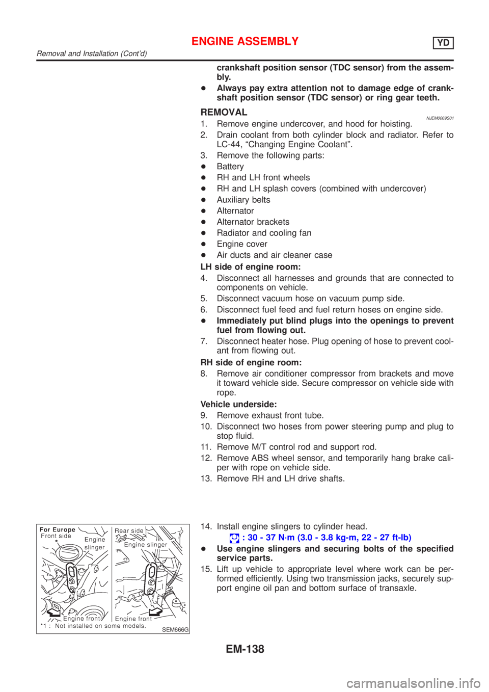
14. Install engine slingers to cylinder head.
: 30 - 37 N´m (3.0 - 3.8 kg-m, 22 - 27 ft-lb)
+Use engine slingers and securing bolts of the specified
service parts.
15. Lift up vehicle to appropriate level where work can be per-
formed efficiently. Using two transmission jacks, securely sup-
port engine oil pan and bottom surface of transaxle.
ENGINE ASSEMBLYYD
Removal and Installation (Cont'd)
EM-138
Page 2276 of 2898
JEM193G
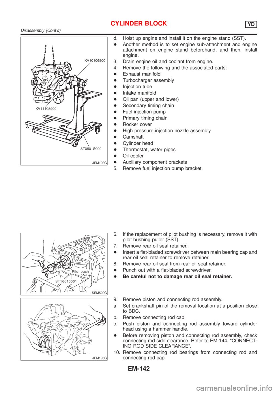
d. Hoist up engine and install it on the engine stand (SST).
+Another method is to set engine sub-attachment and engine
attachment on engine stand beforehand, and then, install
engine.
3. Drain engine oil and coolant from engine.
4. Remove the following and the associated parts:
+Exhaust manifold
+Turbocharger assembly
+Injection tube
+Intake manifold
+Oil pan (upper and lower)
+Secondary timing chain
+Fuel injection pump
+Primary timing chain
+Rocker cover
+High pressure injection nozzle assembly
+Camshaft
+Cylinder head
+Thermostat, water pipes
+Oil cooler
+Auxiliary component brackets
5. Remove fuel injection pump bracket.
SEM500G
6. If the replacement of pilot bushing is necessary, remove it with
pilot bushing puller (SST).
7. Remove rear oil seal retainer.
+Insert a flat-bladed screwdriver between main bearing cap and
rear oil seal retainer to remove retainer.
8. Remove rear oil seal from rear oil seal retainer.
+Punch out with a flat-bladed screwdriver.
+Be careful not to damage rear oil seal retainer.
JEM195G
9. Remove piston and connecting rod assembly.
a. Set crankshaft pin of the removal location at a position close
to BDC.
b. Remove connecting rod cap.
c. Push piston and connecting rod assembly toward cylinder
head using a hammer handle.
+Before removing piston and connecting rod assembly, check
connecting rod side clearance. Refer to EM-144, ªCONNECT-
ING ROD SIDE CLEARANCEº.
10. Remove connecting rod bearings from connecting rod and
connecting rod cap.
CYLINDER BLOCKYD
Disassembly (Cont'd)
EM-142
Page 2292 of 2898
JEM233G
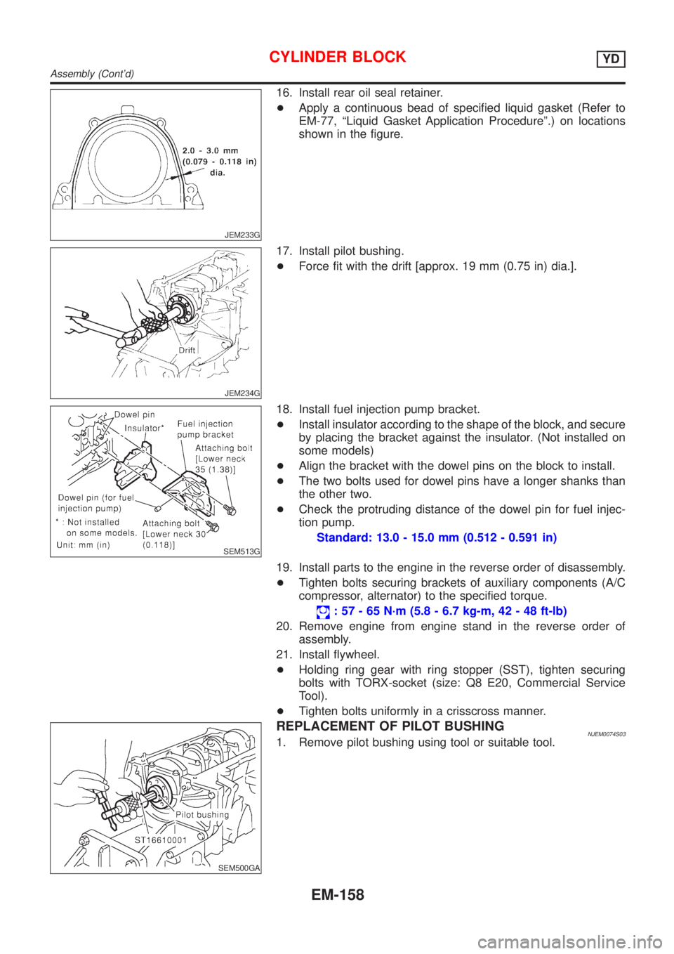
16. Install rear oil seal retainer.
+Apply a continuous bead of specified liquid gasket (Refer to
EM-77, ªLiquid Gasket Application Procedureº.) on locations
shown in the figure.
JEM234G
17. Install pilot bushing.
+Force fit with the drift [approx. 19 mm (0.75 in) dia.].
SEM513G
18. Install fuel injection pump bracket.
+Install insulator according to the shape of the block, and secure
by placing the bracket against the insulator. (Not installed on
some models)
+Align the bracket with the dowel pins on the block to install.
+The two bolts used for dowel pins have a longer shanks than
the other two.
+Check the protruding distance of the dowel pin for fuel injec-
tion pump.
Standard: 13.0 - 15.0 mm (0.512 - 0.591 in)
19. Install parts to the engine in the reverse order of disassembly.
+Tighten bolts securing brackets of auxiliary components (A/C
compressor, alternator) to the specified torque.
: 57 - 65 N´m (5.8 - 6.7 kg-m, 42 - 48 ft-lb)
20. Remove engine from engine stand in the reverse order of
assembly.
21. Install flywheel.
+Holding ring gear with ring stopper (SST), tighten securing
bolts with TORX-socket (size: Q8 E20, Commercial Service
Tool).
+Tighten bolts uniformly in a crisscross manner.
SEM500GA
REPLACEMENT OF PILOT BUSHINGNJEM0074S031. Remove pilot bushing using tool or suitable tool.
CYLINDER BLOCKYD
Assembly (Cont'd)
EM-158
Page 2397 of 2898
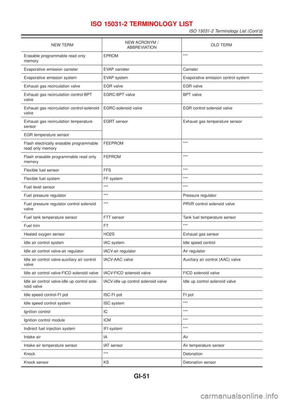
NEW TERMNEW ACRONYM /
ABBREVIATIONOLD TERM
Erasable programmable read only
memoryEPROM ***
Evaporative emission canister EVAP canister Canister
Evaporative emission system EVAP system Evaporative emission control system
Exhaust gas recirculation valve EGR valve EGR valve
Exhaust gas recirculation control-BPT
valveEGRC-BPT valve BPT valve
Exhaust gas recirculation control-solenoid
valveEGRC-solenoid valve EGR control solenoid valve
Exhaust gas recirculation temperature
sensorEGRT sensor Exhaust gas temperature sensor
EGR temperature sensor
Flash electrically erasable programmable
read only memoryFEEPROM ***
Flash erasable programmable read only
memoryFEPROM ***
Flexible fuel sensor FFS ***
Flexible fuel system FF system ***
Fuel level sensor *** ***
Fuel pressure regulator *** Pressure regulator
Fuel pressure regulator control solenoid
valve*** PRVR control solenoid valve
Fuel tank temperature sensor FTT sensor Tank fuel temperature sensor
Fuel trim FT ***
Heated oxygen sensor HO2S Exhaust gas sensor
Idle air control system IAC system Idle speed control
Idle air control valve-air regulator IACV-air regulator Air regulator
Idle air control valve-auxiliary air control
valveIACV-AAC valve Auxiliary air control (AAC) valve
Idle air control valve-FICD solenoid valve IACV-FICD solenoid valve FICD solenoid valve
Idle air control valve-idle up control sole-
noid valveIACV-idle up control solenoid valve Idle up control solenoid valve
Idle speed control-FI pot ISC-FI pot FI pot
Idle speed control system ISC system ***
Ignition control IC ***
Ignition control module ICM ***
Indirect fuel injection system IFI system ***
Intake air IA Air
Intake air temperature sensor IAT sensor Air temperature sensor
Knock *** Detonation
Knock sensor KS Detonation sensor
ISO 15031-2 TERMINOLOGY LIST
ISO 15031-2 Terminology List (Cont'd)
GI-51
Page 2401 of 2898
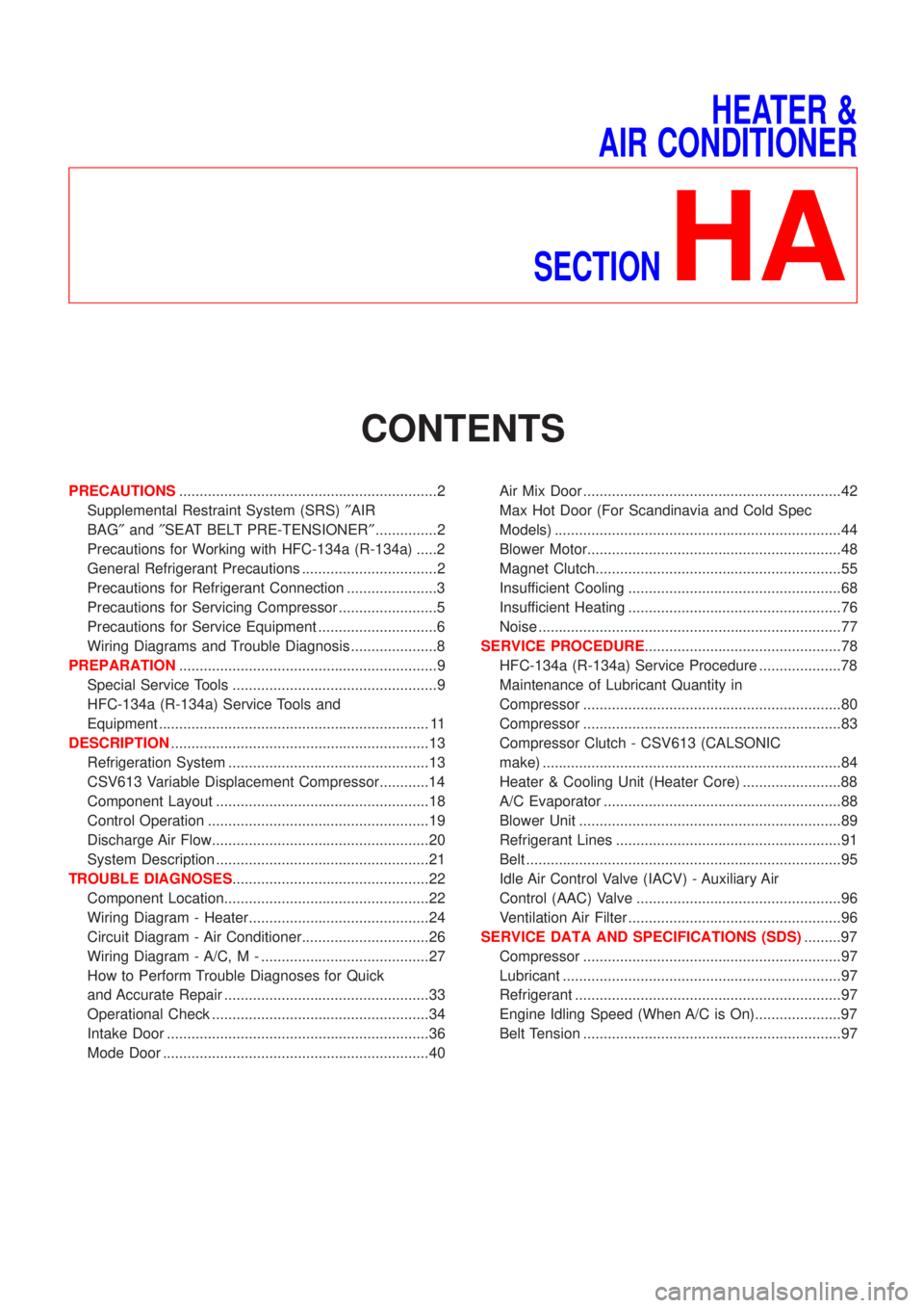
HEATER &
AIR CONDITIONER
SECTION
HA
CONTENTS
PRECAUTIONS...............................................................2
Supplemental Restraint System (SRS)²AIR
BAG²and²SEAT BELT PRE-TENSIONER²...............2
Precautions for Working with HFC-134a (R-134a) .....2
General Refrigerant Precautions .................................2
Precautions for Refrigerant Connection ......................3
Precautions for Servicing Compressor ........................5
Precautions for Service Equipment .............................6
Wiring Diagrams and Trouble Diagnosis .....................8
PREPARATION...............................................................9
Special Service Tools ..................................................9
HFC-134a (R-134a) Service Tools and
Equipment .................................................................. 11
DESCRIPTION...............................................................13
Refrigeration System .................................................13
CSV613 Variable Displacement Compressor............14
Component Layout ....................................................18
Control Operation ......................................................19
Discharge Air Flow.....................................................20
System Description ....................................................21
TROUBLE DIAGNOSES................................................22
Component Location..................................................22
Wiring Diagram - Heater............................................24
Circuit Diagram - Air Conditioner...............................26
Wiring Diagram - A/C, M - .........................................27
How to Perform Trouble Diagnoses for Quick
and Accurate Repair ..................................................33
Operational Check .....................................................34
Intake Door ................................................................36
Mode Door .................................................................40Air Mix Door ...............................................................42
Max Hot Door (For Scandinavia and Cold Spec
Models) ......................................................................44
Blower Motor..............................................................48
Magnet Clutch............................................................55
Insufficient Cooling ....................................................68
Insufficient Heating ....................................................76
Noise ..........................................................................77
SERVICE PROCEDURE................................................78
HFC-134a (R-134a) Service Procedure ....................78
Maintenance of Lubricant Quantity in
Compressor ...............................................................80
Compressor ...............................................................83
Compressor Clutch - CSV613 (CALSONIC
make) .........................................................................84
Heater & Cooling Unit (Heater Core) ........................88
A/C Evaporator ..........................................................88
Blower Unit ................................................................89
Refrigerant Lines .......................................................91
Belt .............................................................................95
Idle Air Control Valve (IACV) - Auxiliary Air
Control (AAC) Valve ..................................................96
Ventilation Air Filter ....................................................96
SERVICE DATA AND SPECIFICATIONS (SDS).........97
Compressor ...............................................................97
Lubricant ....................................................................97
Refrigerant .................................................................97
Engine Idling Speed (When A/C is On).....................97
Belt Tension ...............................................................97
Page 2496 of 2898
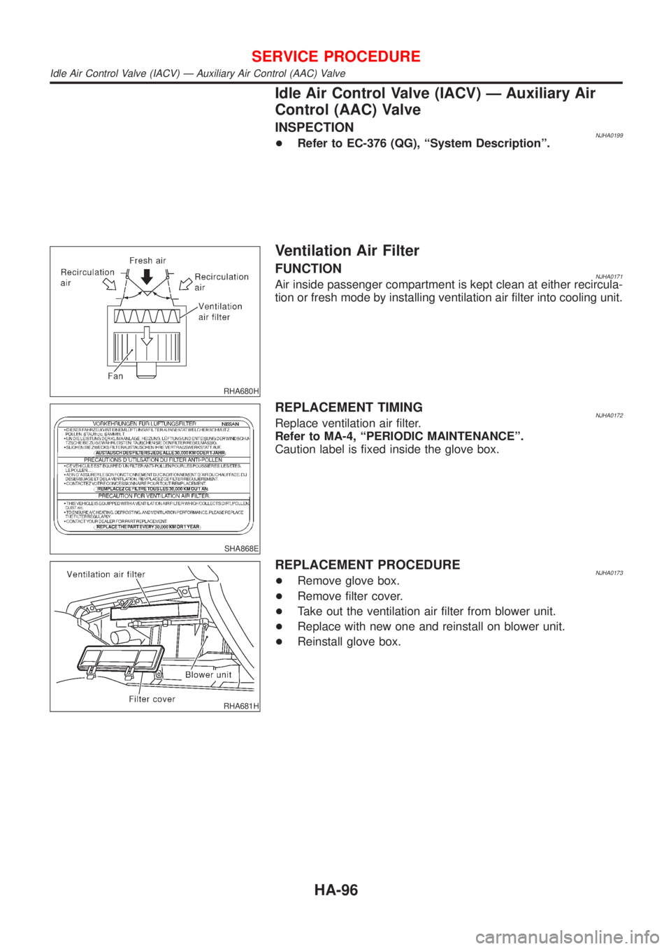
Idle Air Control Valve (IACV) Ð Auxiliary Air
Control (AAC) Valve
INSPECTIONNJHA0199+Refer to EC-376 (QG), ªSystem Descriptionº.
RHA680H
Ventilation Air Filter
FUNCTIONNJHA0171Air inside passenger compartment is kept clean at either recircula-
tion or fresh mode by installing ventilation air filter into cooling unit.
SHA868E
REPLACEMENT TIMINGNJHA0172Replace ventilation air filter.
Refer to MA-4, ªPERIODIC MAINTENANCEº.
Caution label is fixed inside the glove box.
RHA681H
REPLACEMENT PROCEDURENJHA0173+Remove glove box.
+Remove filter cover.
+Take out the ventilation air filter from blower unit.
+Replace with new one and reinstall on blower unit.
+Reinstall glove box.
SERVICE PROCEDURE
Idle Air Control Valve (IACV) Ð Auxiliary Air Control (AAC) Valve
HA-96
Page 2500 of 2898
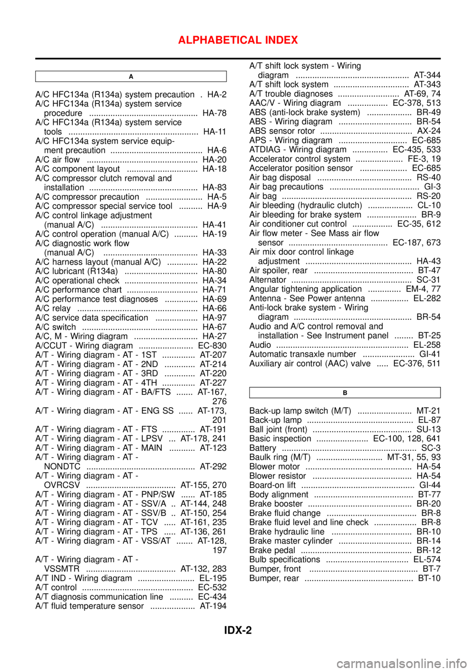
A
A/C HFC134a (R134a) system precaution . HA-2
A/C HFC134a (R134a) system service
procedure .............................................. HA-78
A/C HFC134a (R134a) system service
tools ....................................................... HA-11
A/C HFC134a system service equip-
ment precaution ....................................... HA-6
A/C air flow ............................................... HA-20
A/C component layout .............................. HA-18
A/C compressor clutch removal and
installation .............................................. HA-83
A/C compressor precaution ........................ HA-5
A/C compressor special service tool .......... HA-9
A/C control linkage adjustment
(manual A/C) ......................................... HA-41
A/C control operation (manual A/C) .......... HA-19
A/C diagnostic work flow
(manual A/C) ........................................ HA-33
A/C harness layout (manual A/C) ............. HA-22
A/C lubricant (R134a) ............................... HA-80
A/C operational check ............................... HA-34
A/C performance chart .............................. HA-71
A/C performance test diagnoses .............. HA-69
A/C relay ................................................... HA-66
A/C service data specification .................. HA-97
A/C switch ................................................. HA-67
A/C, M - Wiring diagram ........................... HA-27
A/CCUT - Wiring diagram ....................... EC-830
A/T - Wiring diagram - AT - 1ST .............. AT-207
A/T - Wiring diagram - AT - 2ND ............. AT-214
A/T - Wiring diagram - AT - 3RD ............. AT-220
A/T - Wiring diagram - AT - 4TH .............. AT-227
A/T - Wiring diagram - AT - BA/FTS ....... AT-167,
276
A/T - Wiring diagram - AT - ENG SS ...... AT-173,
201
A/T - Wiring diagram - AT - FTS .............. AT-191
A/T - Wiring diagram - AT - LPSV ... AT-178, 241
A/T - Wiring diagram - AT - MAIN ........... AT-123
A/T - Wiring diagram - AT -
NONDTC .............................................. AT-292
A/T - Wiring diagram - AT -
OVRCSV ...................................... AT-155, 270
A/T - Wiring diagram - AT - PNP/SW ...... AT-185
A/T - Wiring diagram - AT - SSV/A .. AT-144, 248
A/T - Wiring diagram - AT - SSV/B .. AT-150, 254
A/T - Wiring diagram - AT - TCV ..... AT-161, 235
A/T - Wiring diagram - AT - TPS ..... AT-136, 261
A/T - Wiring diagram - AT - VSS/AT ....... AT-128,
197
A/T - Wiring diagram - AT -
VSSMTR ...................................... AT-132, 283
A/T IND - Wiring diagram ........................ EL-195
A/T control ............................................... EC-532
A/T diagnosis communication line .......... EC-434
A/T fluid temperature sensor ................... AT-194A/T shift lock system - Wiring
diagram ................................................ AT-344
A/T shift lock system ................................ AT-343
A/T trouble diagnoses .......................... AT-69, 74
AAC/V - Wiring diagram ................. EC-378, 513
ABS (anti-lock brake system) ................... BR-49
ABS - Wiring diagram ............................... BR-54
ABS sensor rotor ....................................... AX-24
APS - Wiring diagram ............................. EC-685
ATDIAG - Wiring diagram ............... EC-435, 533
Accelerator control system .................... FE-3, 19
Accelerator position sensor .................... EC-685
Air bag disposal ........................................ RS-40
Air bag precautions ...................................... GI-3
Air bag ....................................................... RS-20
Air bleeding (hydraulic clutch) ................... CL-10
Air bleeding for brake system ..................... BR-9
Air conditioner cut control ................. EC-35, 612
Air flow meter - See Mass air flow
sensor .......................................... EC-187, 673
Air mix door control linkage
adjustment ............................................. HA-43
Air spoiler, rear .......................................... BT-47
Alternator ................................................... SC-31
Angular tightening application .............. EM-4, 77
Antenna - See Power antenna ................ EL-282
Anti-lock brake system - Wiring
diagram .................................................. BR-54
Audio and A/C control removal and
installation - See Instrument panel ........ BT-25
Audio ........................................................ EL-258
Automatic transaxle number ...................... GI-41
Auxiliary air control (AAC) valve ..... EC-376, 511
B
Back-up lamp switch (M/T) ....................... MT-21
Back-up lamp ............................................. EL-87
Ball joint (front) .......................................... SU-13
Basic inspection ...................... EC-100, 128, 641
Battery ......................................................... SC-3
Baulk ring (M/T) ............................ MT-31, 55, 93
Blower motor ............................................. HA-54
Blower resistor .......................................... HA-54
Board-on lift ................................................ GI-44
Body alignment .......................................... BT-77
Brake booster ............................................ BR-20
Brake fluid change ...................................... BR-8
Brake fluid level and line check .................. BR-8
Brake hydraulic line .................................. BR-10
Brake master cylinder ............................... BR-14
Brake pedal ............................................... BR-12
Bulb specifications ................................... EL-574
Bumper, front .............................................. BT-7
Bumper, rear .............................................. BT-10
ALPHABETICAL INDEX
IDX-2