Page 25 of 2898

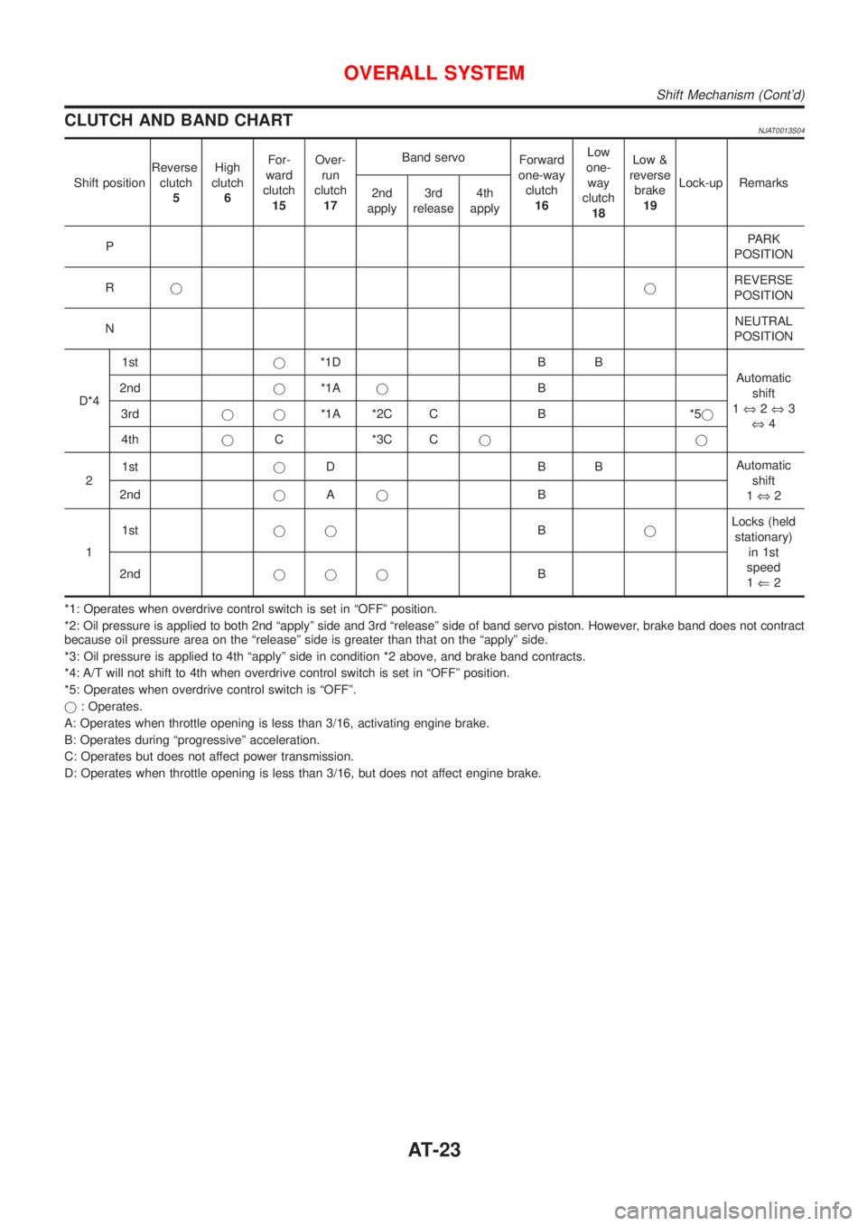
CLUTCH AND BAND CHARTNJAT0013S04
Shift positionReverse
clutch
5High
clutch
6For-
ward
clutch
15Over-
run
clutch
17Band servo
Forward
one-way
clutch
16Low
one-
way
clutch
18Low &
reverse
brake
19Lock-up Remarks
2nd
apply3rd
release4th
apply
PPARK
POSITION
RjjREVERSE
POSITION
NNEUTRAL
POSITION
D*41stj*1D B B
Automatic
shift
1Û2Û3
Û4 2ndj*1AjB
3rdjj*1A *2C C B *5j
4thjC *3C Cjj
21stjDBBAutomatic
shift
1Û2 2ndjAjB
11stjjBjLocks (held
stationary)
in 1st
speed
1Ü2 2ndjjjB
*1: Operates when overdrive control switch is set in ªOFFº position.
*2: Oil pressure is applied to both 2nd ªapplyº side and 3rd ªreleaseº side of band servo piston. However, brake band does not contract
because oil pressure area on the ªreleaseº side is greater than that on the ªapplyº side.
*3: Oil pressure is applied to 4th ªapplyº side in condition *2 above, and brake band contracts.
*4: A/T will not shift to 4th when overdrive control switch is set in ªOFFº position.
*5: Operates when overdrive control switch is ªOFFº.
j: Operates.
A: Operates when throttle opening is less than 3/16, activating engine brake.
B: Operates during ªprogressiveº acceleration.
C: Operates but does not affect power transmission.
D: Operates when throttle opening is less than 3/16, but does not affect engine brake.
OVERALL SYSTEM
Shift Mechanism (Cont'd)
AT-23
Page 37 of 2898

Pilot pressure generated by the operation of shift solenoid valves
A and B is applied to the end face of shift valves A and B.
The drawing above shows the operation of shift valve B. When the
shift solenoid valve is ªONº, pilot pressure applied to the end face
of the shift valve overcomes spring force, moving the valve upward.
LOCK-UP CONTROLNJAT0015S03The torque converter clutch piston in the torque converter is locked
to eliminate torque converter slip to increase power transmission
efficiency. The solenoid valve is controlled by an ON-OFF duty
signal sent from the TCM. The signal is converted to an oil pres-
sure signal which controls the torque converter clutch piston.
Conditions for Lock-up OperationNJAT0015S0301When vehicle is driven in 4th gear position, vehicle speed and
throttle opening are detected. If the detected values fall within the
lock-up zone memorized in the TCM, lock-up is performed.
Overdrive control switch ON OFF
Selector lever ªDº position
Gear position D
4D3
Vehicle speed sensor More than set value
Throttle position sensor Less than set opening
Closed throttle position switch OFF
A/T fluid temperature sensor More than 40ÉC (104ÉF)
SAT010J
Torque Converter Clutch Solenoid Valve ControlNJAT0015S0302The torque converter clutch solenoid valve is controlled by the
TCM. The plunger closes the drain circuit during the ªOFFº period,
and opens the circuit during the ªONº period. If the percentage of
OFF-time increases in one cycle, the pilot pressure drain time is
reduced and pilot pressure remains high.
The torque converter clutch piston is designed to slip to adjust the
ratio of ON-OFF, thereby reducing lock-up shock.
SAT011J
OFF-time INCREASING
¯
Amount of drain DECREASING
¯
Pilot pressure HIGH
¯
Lock-up RELEASING
OVERALL SYSTEM
Control Mechanism (Cont'd)
AT-35
Page 82 of 2898

SAT767B
A/T Fluid CheckNJAT0025FLUID LEAKAGE CHECKNJAT0025S011. Clean area suspected of leaking. Ð for example, mating sur-
face of converter housing and transmission case.
2. Start engine, apply foot brake, place selector lever in ªDº posi-
tion and wait a few minutes.
3. Stop engine.
SAT288G
4. Check for fresh leakage.
SAT638A
FLUID CONDITION CHECKNJAT0025S02
Fluid color Suspected problem
Dark or black with burned odor Wear of frictional material
Milky pink Water contamination Ð Road water
entering through filler tube or breather
Varnished fluid, light to dark brown
and tackyOxidation Ð Over or under filling, Ð
Overheating
FLUID LEVEL CHECKNJAT0025S03Refer to ªChecking A/T Fluidº, AT-15.
SAT647B
Stall TestNJAT0026STALL TEST PROCEDURENJAT0026S011. Check A/T fluid and engine oil levels. If necessary, add.
2. Drive vehicle for approx. 10 minutes or until fluid and oil reach
operating temperature.
ATF operating temperature:
50 - 80ÉC (122 - 176ÉF)
TROUBLE DIAGNOSIS Ð BASIC INSPECTION
A/T Fluid Check
AT-80
Page 116 of 2898

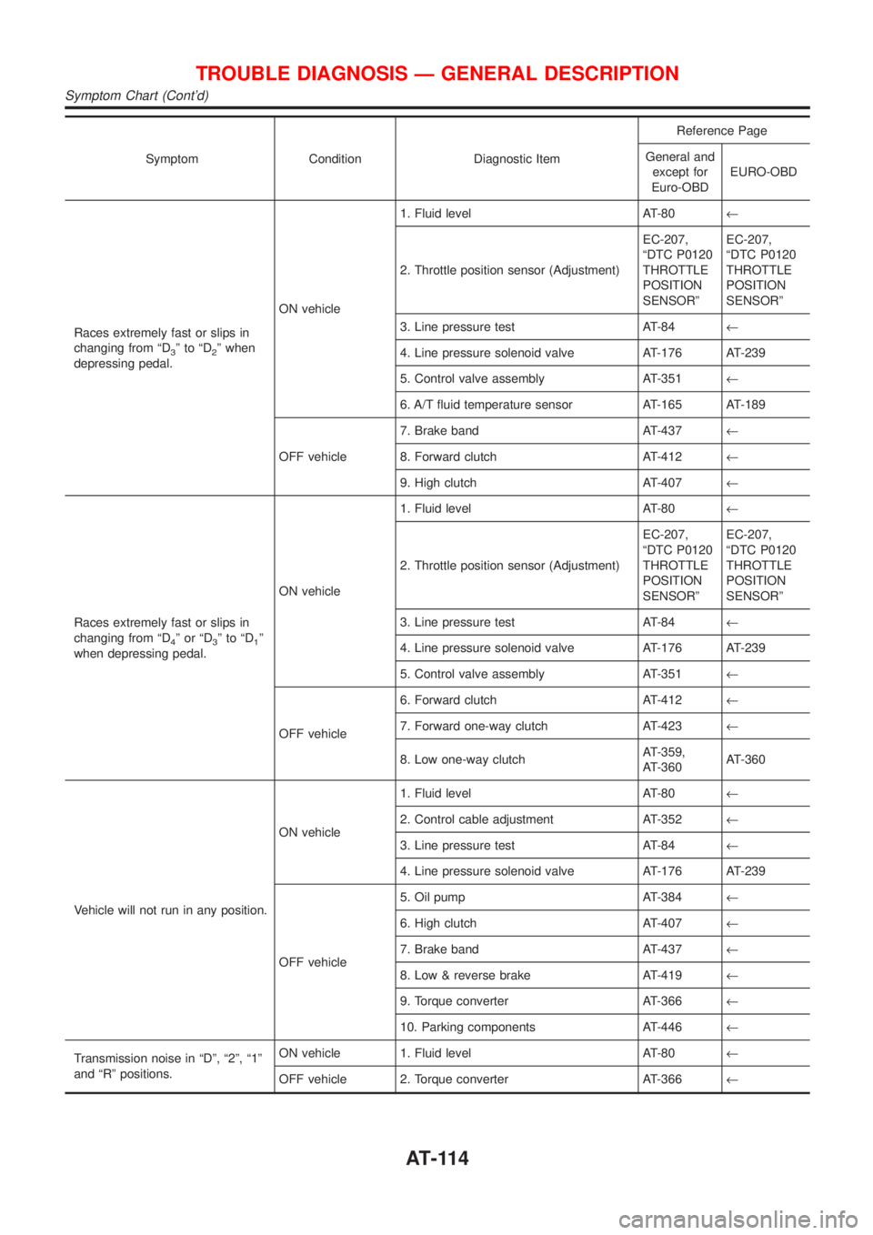
Symptom Condition Diagnostic ItemReference Page
General and
except for
Euro-OBDEURO-OBD
Races extremely fast or slips in
changing from ªD
3ºtoªD2º when
depressing pedal.ON vehicle1. Fluid level AT-80¬
2. Throttle position sensor (Adjustment)EC-207,
ªDTC P0120
THROTTLE
POSITION
SENSORºEC-207,
ªDTC P0120
THROTTLE
POSITION
SENSORº
3. Line pressure test AT-84¬
4. Line pressure solenoid valve AT-176 AT-239
5. Control valve assembly AT-351¬
6. A/T fluid temperature sensor AT-165 AT-189
OFF vehicle7. Brake band AT-437¬
8. Forward clutch AT-412¬
9. High clutch AT-407¬
Races extremely fast or slips in
changing from ªD
4ºorªD3ºtoªD1º
when depressing pedal.ON vehicle1. Fluid level AT-80¬
2. Throttle position sensor (Adjustment)EC-207,
ªDTC P0120
THROTTLE
POSITION
SENSORºEC-207,
ªDTC P0120
THROTTLE
POSITION
SENSORº
3. Line pressure test AT-84¬
4. Line pressure solenoid valve AT-176 AT-239
5. Control valve assembly AT-351¬
OFF vehicle6. Forward clutch AT-412¬
7. Forward one-way clutch AT-423¬
8. Low one-way clutchAT-359,
AT-360AT-360
Vehicle will not run in any position.ON vehicle1. Fluid level AT-80¬
2. Control cable adjustment AT-352¬
3. Line pressure test AT-84¬
4. Line pressure solenoid valve AT-176 AT-239
OFF vehicle5. Oil pump AT-384¬
6. High clutch AT-407¬
7. Brake band AT-437¬
8. Low & reverse brake AT-419¬
9. Torque converter AT-366¬
10. Parking components AT-446¬
Transmission noise in ªDº, ª2º, ª1º
and ªRº positions.ON vehicle 1. Fluid level AT-80¬
OFF vehicle 2. Torque converter AT-366¬
TROUBLE DIAGNOSIS Ð GENERAL DESCRIPTION
Symptom Chart (Cont'd)
AT-114
Page 118 of 2898

Symptom Condition Diagnostic ItemReference Page
General and
except for
Euro-OBDEURO-OBD
Large shock changing from ª1
2ºto
ª1
1º in ª1º position.ON vehicle 1. Control valve assembly AT-351¬
OFF vehicle 2. Low & reverse brake AT-419¬
Transmission overheats.ON vehicle1. Fluid level AT-80¬
2. Engine idling rpmEC-43, ªIdle
Speed and
Ignition Tim-
ingºEC-43, ªIdle
Speed and
Ignition Tim-
ingº
3. Throttle position sensor (Adjustment)EC-207,
ªDTC P0120
THROTTLE
POSITION
SENSORºEC-207,
ªDTC P0120
THROTTLE
POSITION
SENSORº
4. Line pressure test AT-84¬
5. Line pressure solenoid valve AT-176 AT-239
6. Control valve assembly AT-351¬
OFF vehicle7. Oil pump AT-384¬
8. Reverse clutch AT-403¬
9. High clutch AT-407¬
10. Brake band AT-437¬
11. Forward clutch AT-412¬
12. Overrun clutch AT-412¬
13. Low & reverse brake AT-419¬
14. Torque converter AT-366¬
ATF shoots out during operation.
White smoke emitted from exhaust
pipe during operation.ON vehicle 1. Fluid level AT-80¬
OFF vehicle2. Reverse clutch AT-403¬
3. High clutch AT-407¬
4. Brake band AT-437¬
5. Forward clutch AT-412¬
6. Overrun clutch AT-412¬
7. Low & reverse brake AT-419¬
Offensive smell at fluid charging
pipe.ON vehicle 1. Fluid level AT-80¬
OFF vehicle2. Torque converter AT-366¬
3. Oil pump AT-384¬
4. Reverse clutch AT-403¬
5. High clutch AT-407¬
6. Brake band AT-437¬
7. Forward clutch AT-412¬
8. Overrun clutch AT-412¬
9. Low & reverse brake AT-419¬
TROUBLE DIAGNOSIS Ð GENERAL DESCRIPTION
Symptom Chart (Cont'd)
AT-116
Page 353 of 2898
SAT992C
Control Valve Assembly and AccumulatorsNJAT0110REMOVALNJAT0110S011. Drain ATF from transaxle.
2. Remove oil pan and gasket.
SAT064K
3. Disconnect A/T solenoid valve harness connector.
AAT265A
4. Remove stopper ring from A/T solenoid harness terminal body.
5. Remove A/T solenoid harness by pushing terminal body into
transmission case.
AAT260A
6. Remove control valve assembly by removing fixing bolts.
Bolt length, number and location:
Bolt symbol A B C
Bolt length ª!º
40.0 mm
(1.575 in)33.0 mm
(1.299 in)43.5 mm
(1.713 in)
Number of bolts 5 6 2
+Be careful not to drop manual valve and servo release
accumulator return springs.
7. Disassemble and inspect control valve assembly if necessary.
Refer to AT-366.
ON-VEHICLE SERVICE
Control Valve Assembly and Accumulators
AT-351
Page 372 of 2898
SAT030D
20. Remove final drive assembly from transmission case.
NAT033
21. Remove differential side bearing outer race from transmission
case.
SAT132E
22. Remove differential side bearing adjusting shim from transmis-
sion case.
SAT840DB
23. Remove differential side bearing outer race from converter
housing.
SAT133E
24. Remove oil seal from converter housing using a screwdriver.
+Be careful not to damage case.
DISASSEMBLY
AT-370
Page 373 of 2898
SAT072D
25. Remove side oil seal from transmission case using a screw-
driver.
SAT134EA
26. Remove oil tube from converter housing.
SAT127E
27. Remove oil pump according to the following procedures.
a. Remove O-ring from input shaft.
SAT035D
b. Remove oil pump assembly from transmission case.
SAT036D
c. Remove thrust washer and bearing race from oil pump assem-
bly.
DISASSEMBLY
AT-371