2001 NISSAN ALMERA horn
[x] Cancel search: hornPage 1560 of 2898
Wiring Diagram - ROOM/L -/Sedan With Interior
Room Lamp Timer ................................................... 117
Trouble Diagnoses/Sedan With Interior Room
Lamp Timer .............................................................. 119
System Description/Hatchback With Interior
Room Lamp Timer ...................................................127
Wiring Diagram - ROOM/L -/Hatchback With
Interior Room Lamp Timer.......................................129
Trouble Diagnoses/Hatchback With Interior
Room Lamp Timer ...................................................131
Wiring Diagram - ROOM/L -/Sedan Without
Timer ........................................................................139
Wiring Diagram - ROOM/L -/Hatchback Without
Timer ........................................................................140
SPOT AND TRUNK ROOM LAMPS...........................141
Wiring Diagram - INT/L -/Sedan ..............................141
Wiring Diagram - INT/L -/Hatchback .......................143
METERS AND GAUGES.............................................144
Component Parts and Harness Connector
Location/Sedan ........................................................144
System Description/Sedan ......................................144
Combination Meter/Sedan With Tachometer...........146
Schematic/Sedan With Tachometer ........................147
Combination Meter/Without Tachometer .................148
Schematic/Without Tachometer ...............................149
Construction/Sedan .................................................150
Wiring Diagram - METER -/Without Tachometer ....151
Wiring Diagram - METER -/Sedan ..........................152
Meter/Gauge Operation and Odo/Trip Meter
Segment Check in Diagnosis Mode/Sedan.............153
Trouble Diagnoses/Sedan .......................................154
Electrical Components Inspection/Sedan ................162
Component Parts and Harness Connector
Location/Hatchback .................................................164
System Description/Hatchback ................................164
Combination Meter/Hatchback (Models before
VIN No. - N16U0135126) ........................................166
Combination Meter/Hatchback (Models after VIN
No. - N16U0135126) ...............................................167
Schematic/Hatchback (Models before VIN No. -
N160135126) ...........................................................168
Schematic/Hatchback (Models after VIN No. -
N16U0135126).........................................................169
Construction/Hatchback ...........................................170
Wiring Diagram - METER -/Hatchback ...................171
Combination Meter Self-Diagnosis/Hatchback ........173
Trouble Diagnoses/Hatchback.................................176
Electrical Components Inspection/Hatchback .........183
WARNING LAMPS......................................................184
Schematic/Sedan .....................................................184
Wiring Diagram - WARN -/Sedan ............................185
Schematic/Hatchback ..............................................189Wiring Diagram - WARN -/Hatchback .....................190
Electrical Components Inspection ...........................194
A/T INDICATOR...........................................................195
Wiring Diagram - AT/IND -/With Tachometer...........195
Wiring Diagram - AT/IND -/Without Tachometer......196
WARNING CHIME.......................................................197
Component Parts and Harness Connector
Location/Sedan ........................................................197
System Description/Sedan ......................................198
Wiring Diagram - CHIME -/Sedan ...........................199
Trouble Diagnoses/Sedan .......................................200
Component Parts and Harness Connector
Location/Hatchback .................................................205
System Description/Hatchback ................................206
Wiring Diagram - CHIME -/Hatchback ....................207
Trouble Diagnoses/Hatchback.................................209
FRONT WIPER AND WASHER..................................215
System Description/Sedan ......................................215
Wiring Diagram - WIPER -/Sedan ...........................217
System Description/Hatchback ................................218
Wiring Diagram - WIPER -/Hatchback ....................220
Removal and Installation .........................................222
Washer Nozzle Adjustment .....................................223
Washer Tube Layout ...............................................224
REAR WIPER AND WASHER....................................225
Wiring Diagram - WIP/R -/Sedan ............................225
Wiring Diagram - WIP/R -/Hatchback......................227
Removal and Installation .........................................229
Washer Nozzle Adjustment .....................................229
Washer Tube Layout ...............................................230
HEADLAMP WASHER................................................231
Wiring Diagram - HLC -/Sedan ...............................231
Wiring Diagram - HLC -/Hatchback .........................232
Washer Tube Layout ...............................................233
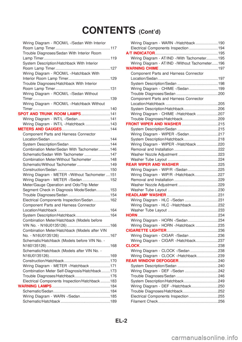
HORN...........................................................................234
Wiring Diagram - HORN -/Sedan ............................234
Wiring Diagram - HORN -/Hatchback .....................235
CIGARETTE LIGHTER................................................236
Wiring Diagram - CIGAR -/Sedan ...........................236
Wiring Diagram - CIGAR -/Hatchback.....................237
CLOCK.........................................................................238
Wiring Diagram - CLOCK -/Sedan ..........................238
Wiring Diagram - CLOCK -/Hatchback....................239
REAR WINDOW DEFOGGER.....................................240
System Description/Sedan ......................................240
Wiring Diagram - DEF -/Sedan ...............................242
Trouble Diagnoses/Sedan .......................................246
System Description/Hatchback ................................249
Wiring Diagram - DEF -/Hatchback .........................250
Trouble Diagnoses/Hatchback.................................252
Electrical Components Inspection ...........................255
Filament Check ........................................................256
CONTENTS(Cont'd)
EL-2
Page 1792 of 2898

Wiring Diagram Ð HORN Ð/SedanNJEL0071
HEL392B
HORN
Wiring Diagram Ð HORN Ð/Sedan
EL-234
Page 1793 of 2898
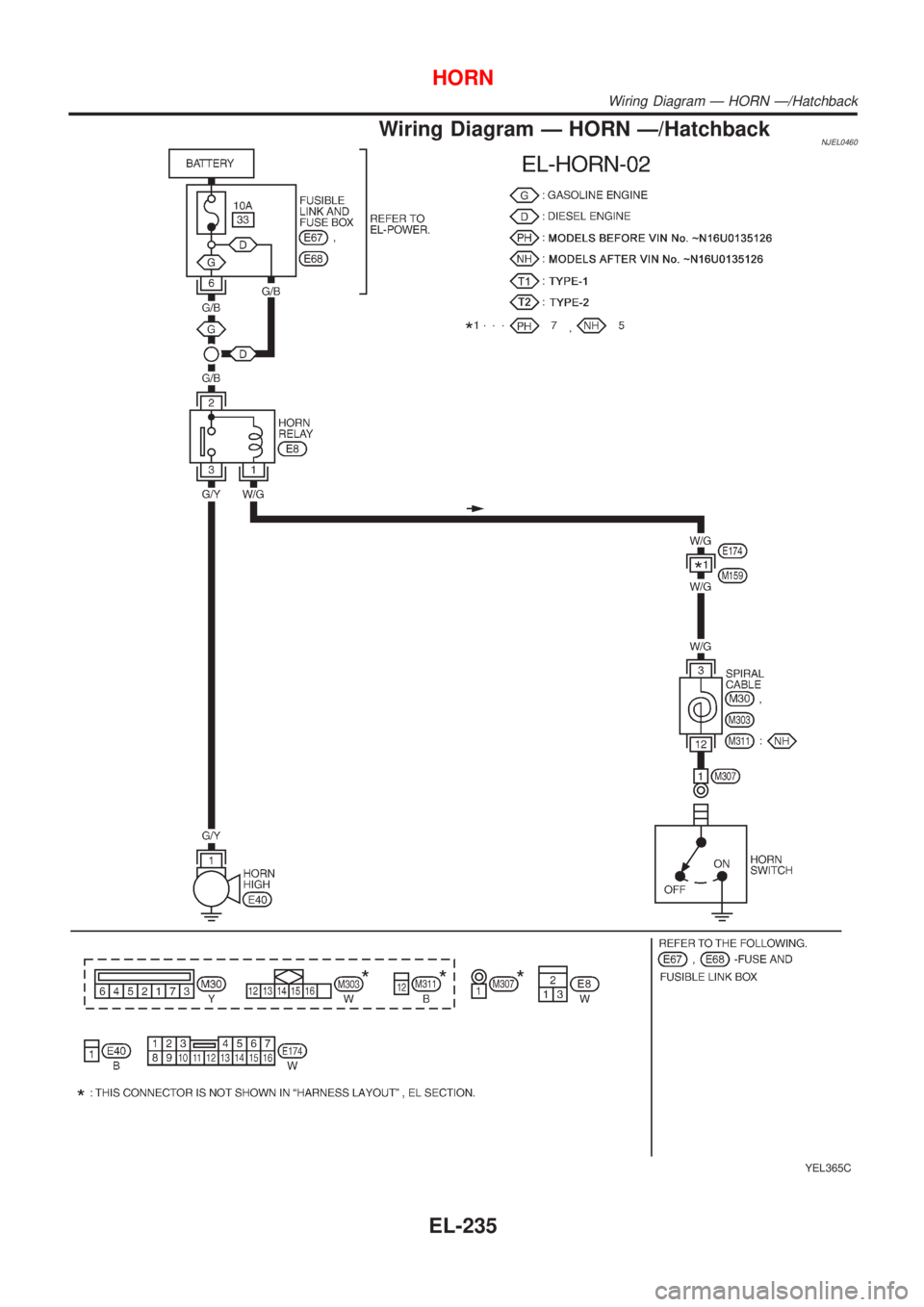
Wiring Diagram Ð HORN Ð/HatchbackNJEL0460
YEL365C
HORN
Wiring Diagram Ð HORN Ð/Hatchback
EL-235
Page 2133 of 2898
NJEL0311
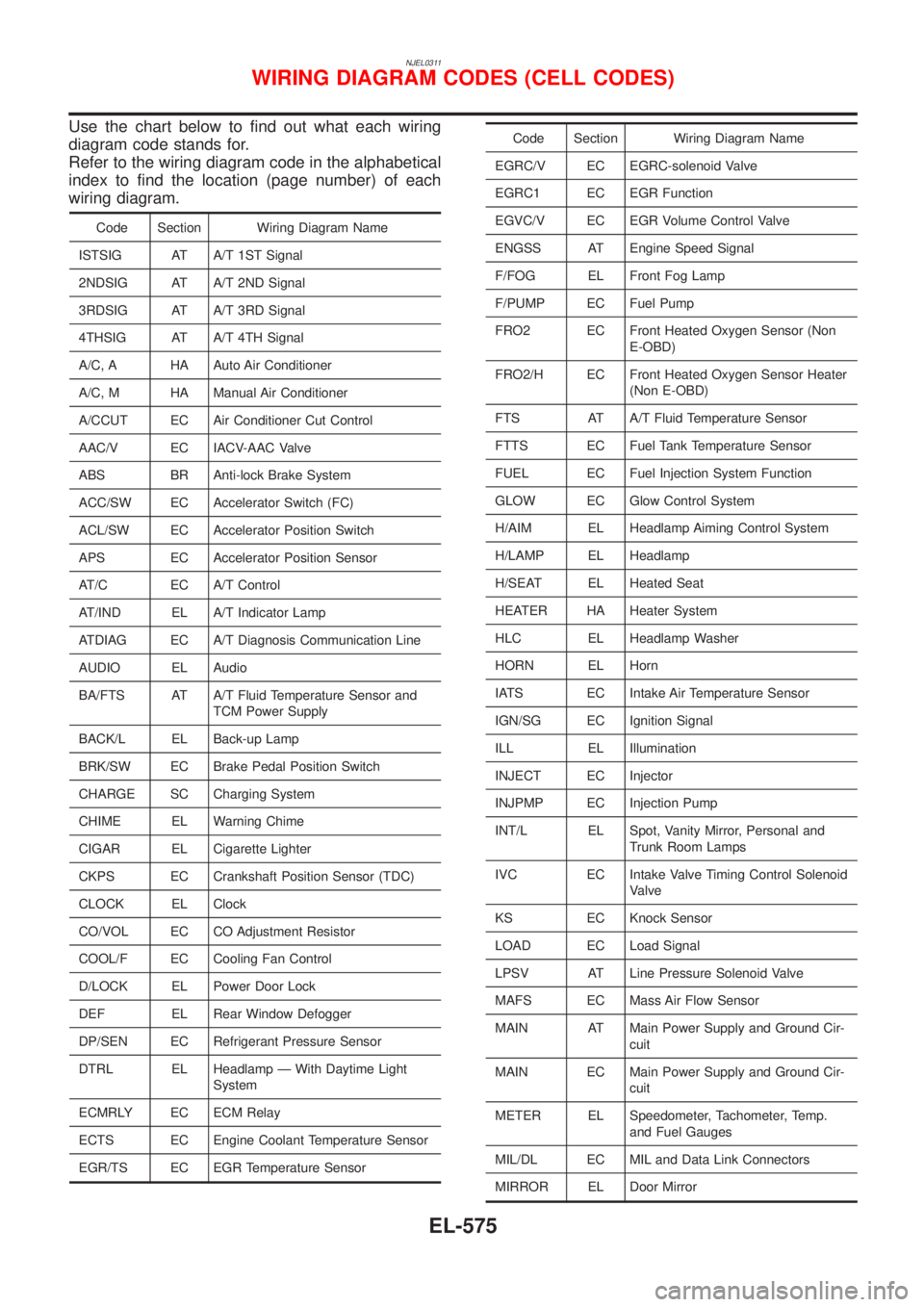
Use the chart below to find out what each wiring
diagram code stands for.
Refer to the wiring diagram code in the alphabetical
index to find the location (page number) of each
wiring diagram.
Code Section Wiring Diagram Name
ISTSIG AT A/T 1ST Signal
2NDSIG AT A/T 2ND Signal
3RDSIG AT A/T 3RD Signal
4THSIG AT A/T 4TH Signal
A/C, A HA Auto Air Conditioner
A/C, M HA Manual Air Conditioner
A/CCUT EC Air Conditioner Cut Control
AAC/V EC IACV-AAC Valve
ABS BR Anti-lock Brake System
ACC/SW EC Accelerator Switch (FC)
ACL/SW EC Accelerator Position Switch
APS EC Accelerator Position Sensor
AT/C EC A/T Control
AT/IND EL A/T Indicator Lamp
ATDIAG EC A/T Diagnosis Communication Line
AUDIO EL Audio
BA/FTS AT A/T Fluid Temperature Sensor and
TCM Power Supply
BACK/L EL Back-up Lamp
BRK/SW EC Brake Pedal Position Switch
CHARGE SC Charging System
CHIME EL Warning Chime
CIGAR EL Cigarette Lighter
CKPS EC Crankshaft Position Sensor (TDC)
CLOCK EL Clock
CO/VOL EC CO Adjustment Resistor
COOL/F EC Cooling Fan Control
D/LOCK EL Power Door Lock
DEF EL Rear Window Defogger
DP/SEN EC Refrigerant Pressure Sensor
DTRL EL Headlamp Ð With Daytime Light
System
ECMRLY EC ECM Relay
ECTS EC Engine Coolant Temperature Sensor
EGR/TS EC EGR Temperature Sensor
Code Section Wiring Diagram Name
EGRC/V EC EGRC-solenoid Valve
EGRC1 EC EGR Function
EGVC/V EC EGR Volume Control Valve
ENGSS AT Engine Speed Signal
F/FOG EL Front Fog Lamp
F/PUMP EC Fuel Pump
FRO2 EC Front Heated Oxygen Sensor (Non
E-OBD)
FRO2/H EC Front Heated Oxygen Sensor Heater
(Non E-OBD)
FTS AT A/T Fluid Temperature Sensor
FTTS EC Fuel Tank Temperature Sensor
FUEL EC Fuel Injection System Function
GLOW EC Glow Control System
H/AIM EL Headlamp Aiming Control System
H/LAMP EL Headlamp
H/SEAT EL Heated Seat
HEATER HA Heater System
HLC EL Headlamp Washer
HORN EL Horn
IATS EC Intake Air Temperature Sensor
IGN/SG EC Ignition Signal
ILL EL Illumination
INJECT EC Injector
INJPMP EC Injection Pump
INT/L EL Spot, Vanity Mirror, Personal and
Trunk Room Lamps
IVC EC Intake Valve Timing Control Solenoid
Valve
KS EC Knock Sensor
LOAD EC Load Signal
LPSV AT Line Pressure Solenoid Valve
MAFS EC Mass Air Flow Sensor
MAIN AT Main Power Supply and Ground Cir-
cuit
MAIN EC Main Power Supply and Ground Cir-
cuit
METER EL Speedometer, Tachometer, Temp.
and Fuel Gauges
MIL/DL EC MIL and Data Link Connectors
MIRROR EL Door Mirror
WIRING DIAGRAM CODES (CELL CODES)
EL-575
Page 2502 of 2898
Electronic fuel injection pump ........ EC-618, 716,
723, 757, 764, 771, 778, 785, 803
Engine compartment ................................. BT-78
Engine control circuit diagram .......... EC-25, 606
Engine control component parts
location .......................................... EC-21, 603
Engine control module (ECM) ....... EC-391, 659,
714, 792, 794, 799, 801
Engine control system diagram and
chart .............................................. EC-29, 608
Engine coolant temperature sensor
(ECTS) ........................................ EC-201, 680
Engine fail-safe system ........................... EC-154
Engine oil precautions .................................. GI-7
Engine outer component parts ................. EM-11
Engine removal ................................ EM-51, 137
Engine room - See Engine
compartment .......................................... BT-78
Engine serial number ................................. GI-41
Evaporative emission (EVAP)
system ................................................... EC-36
Exhaust gas recirculation (EGR)
valve .................................... EC-343, 425, 491
Exhaust system ................................... FE-15, 32
Exterior ...................................................... BT-47
F
F/PUMP - Wiring diagram ....................... EC-563
FR02 - Wiring diagram ... EC-219, 239, 247, 451
FR02/H - Wiring diagram ................ EC-254, 458
FUEL - Wiring diagram ................... EC-299, 307
Fan switch ................................................. HA-54
Final drive (FF A/T) .................................. AT-442
Final drive (FF M/T) .............. MT-44, 77, 93, 107
Finisher, interior - See Trim ....................... BT-31
Finisher, trunk lid ....................................... BT-45
Floor trim ................................................... BT-31
Fluid temperature sensor (A/T) ................ AT-194
Fluids ........................................................ MA-16
Flywheel (clutch) ....................................... CL-22
Flywheel runout ................................ EM-62, 154
Fog lamp, front, removal and
installation ................................................ BT-7
Fog lamp, front .......................................... EL-89
Fork rod (M/T) .............................. MT-32, 56, 94
Forward clutch ......................................... AT-412
Freeze frame data .............................. EC-61, 72
Front axle .................................................... AX-2
Front bumper ............................................... BT-7
Front combination lamp removal and
installation ................................................ BT-7
Front disc brake ........................................ BR-27
Front door .................................................. BT-16
Front fog lamp removal and
installation ................................................ BT-7
Front fog lamp ........................................... EL-89
Front heated oxygen sensor (HO2S)
heater .......................................... EC-252, 457Front heated oxygen sensor (HO2S) ..... EC-216,
224, 230, 236, 245, 450
Front seat belt ............................................. RS-5
Front seat .................................................. BT-56
Front suspension ........................................ SU-2
Front washer ............................................ EL-215
Front wiper ............................................... EL-215
Fuel cut control (at no load & high
engine speed) ............................... EC-36, 612
Fuel gauge ............................................... EL-144
Fuel injection system .............. EC-297, 305, 610
Fuel injector ............................................ EC-541
Fuel precautions ........................................... GI-8
Fuel pressure check ................................. EC-40
Fuel pressure regulator ............................. EC-41
Fuel pressure release ............................... EC-40
Fuel pump relay ...................................... EC-561
Fuel pump ............................................... EC-561
Fuel system ........................................... FE-5, 20
Fuel tank vacuum relief valve ................... EC-37
Fuse block ............................................... EL-577
Fuse ........................................................... EL-38
Fusible link ................................................. EL-38
G
GLOW - Wiring diagram ......................... EC-806
Garage jack and safety stand .................... GI-45
Gauges .................................................... EL-144
Gear components (M/T) ............... MT-31, 55, 93
Generator - See Alternator ....................... SC-31
Generic scan tool (GST) ........................... EC-94
Glass .......................................................... BT-17
Glow plug ................................................ EC-806
Glow relay ............................................... EC-806
Grease ...................................................... MA-16
Ground distribution .................................... EL-39
H
H/LAMP - Wiring diagram ................... EL-60, 61
HEATER - Wiring diagram ........................ HA-24
HFC134a (R134a) system
precaution ................................................ HA-2
HFC134a (R134a) system service
procedure .............................................. HA-78
HFC134a (R134a) system service
tools ....................................................... HA-11
HFC134a system service equipment
precaution ................................................ HA-6
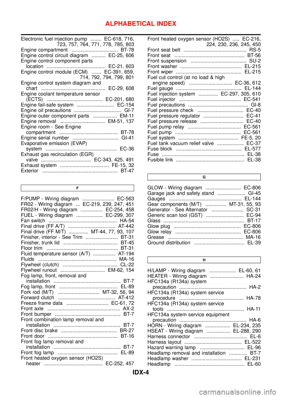
HORN - Wiring diagram .................. EL-234, 235
HSEAT - Wiring diagram ................. EL-288, 290
Harness connector ...................................... EL-6
Harness layout ......................................... EL-522
Hazard warning lamp ................................ EL-96
Headlamp removal and installation ............. BT-7
Headlamp washer .................................... EL-231
Headlamp .................................................. EL-60
ALPHABETICAL INDEX
IDX-4
Page 2503 of 2898
Headlining - See Roof trim ........................ BT-43
Heated oxygen sensor (HO2S)
(front) .......... EC-216, 224, 230, 236, 245, 450
Heated oxygen sensor (HO2S) heater
(front) ........................................... EC-252, 457
Heated oxygen sensor (HO2S) heater
(rear) ............................................ EC-291, 469
Heated oxygen sensor (rear) ......... EC-258, 267,
275, 284, 462
Heated seat ............................................. EL-288
Height (Dimensions) ................................... GI-43
High clutch ............................................... AT-407
Hood ............................................................ BT-7
Horn ......................................................... EL-234
How to erase DTC for OBD system .. EC-70, 73,
627
I
IACV-AAC valve .............................. EC-376, 511
IATS - Wiring diagram .................... EC-196, 444
IGN/SG - Wiring diagram ........................ EC-548
ILL - Wiring diagram ................................ EL-112
INJECT - Wiring diagram ........................ EC-542
INT/L - Wiring diagram .................... EL-141, 143
IVC - Wiring diagram ...................... EC-395, 527
Identification plate ...................................... GI-40
Idle air control (IAC) system ........... EC-376, 511
Idle air control valve (IACV) ............ EC-376, 511
Idle speed ......................................... EC-43, 641
Ignition timing ............................................ EC-43
Illumination ............................................... EL-108
Injection nozzle ....................................... EC-614
Injector removal and installation ............... EC-41
Input shaft (FF M/T) ............... MT-36, 64, 93, 98
Instrument panel ........................................ BT-25
Intake air temperature sensor ......... EC-194, 442
Intake valve timing control solenoid
valve ............................................ EC-393, 526
Interior lamp on-off control .............. EL-116, 128
Interior lamp ............................................. EL-115
Interior ........................................................ BT-31
J
Jacking points ............................................ GI-45
Joint connector (J/C) ............................... EL-583
Junction box (J/B) .................................... EL-577
K
Keyless entry system - See Multi-remote control
system ..................................................... EL-392
Knock sensor (KS) .......................... EC-324, 325
Knuckle spindle ........................................... AX-5
L
LOAD - Wiring diagram .......................... EC-579
Length (Dimensions) .................................. GI-43
License lamp ............................................. EL-81
Lifting points ............................................... GI-46
Line pressure solenoid valve ................... AT-232
Line pressure test (A/T) ............................. AT-84
Liquid gasket application ...................... EM-4, 77
Location of electrical units ....................... EL-517
Lock, door .................................................. BT-21
Low and reverse brake ............................ AT-419
Lubricant (R134a) A/C .............................. HA-80
Lubricants ................................................. MA-16
Lubrication circuit (engine) .................... LC-4, 27
M
M/T major overhaul ....................... MT-30, 54, 92
M/T removal and installation ..................... MT-23
MAFS - Wiring diagram .................. EC-189, 673
MAIN - Wiring diagram ................... EC-178, 666
MAJOR OVERHALL ................................ AT-357
METER - Wiring diagram ........................ EL-151
MIL & Data link connectors circuit .......... EC-591
MIL/DL - Wiring diagram ................. EC-591, 831
MIRROR - Wiring diagram .............. EL-294, 295
Magnet clutch ............................................ HA-83
Mainshaft (M/T) .................... MT-39, 69, 93, 103
Malfunction indicator lamp (MIL) ...... EC-74, 628
Manual air conditioner - Wiring
diagram .................................................. HA-27
Manual transaxle number .......................... GI-42
Mass air flow sensor (MAFS) ......... EC-187, 673
Master cylinder (brake) ............................. BR-14
Master cylinder (clutch) ............................. CL-11
Meter ........................................................ EL-144
Mirror defogger ........................................ EL-240
Mirror, door ................................................ BT-75
Misfire ...................................................... EC-318
Mode door control linkage
adjustment ............................................. HA-41
Model variation ........................................... GI-38
Molding - See Exterior ............................... BT-47
Multi-remote control system .................... EL-392
Multiport fuel injection (MFI) system ......... EC-32
Multiport fuel injection precautions ............... GI-6
N
NATS (Nissan Anti-theft System)
precautions ................................................... GI-3
NATS (Nissan Anti-theft System) ............ EL-422
NATS - Wiring diagram ................... EL-425, 427
NVH troubleshooting (AX) ........................... AX-3
NVH troubleshooting (BR) .......................... BR-7
NVH troubleshooting (MT) ........................ MT-13
NVH troubleshooting (ST) ........................... ST-5
ALPHABETICAL INDEX
IDX-5
Page 2519 of 2898
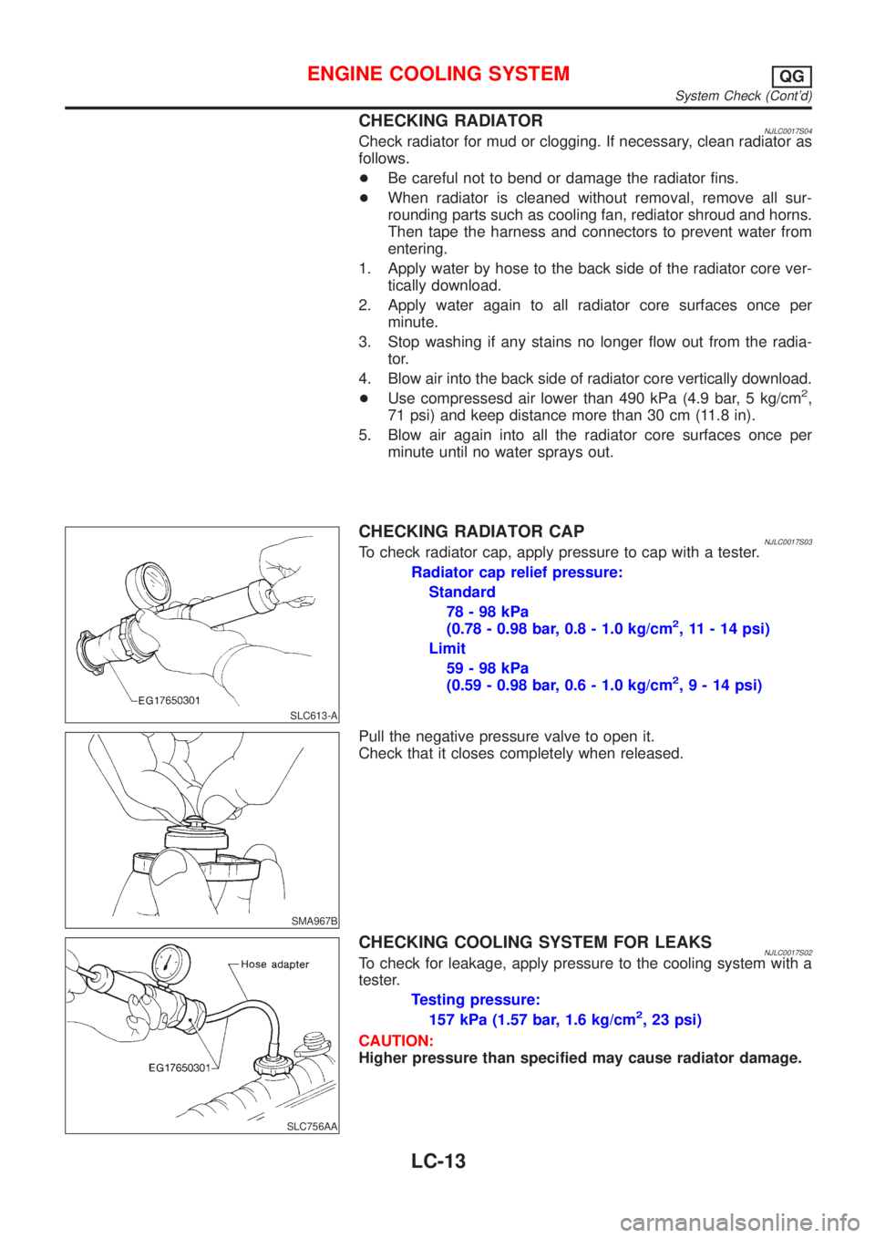
CHECKING RADIATORNJLC0017S04Check radiator for mud or clogging. If necessary, clean radiator as
follows.
+Be careful not to bend or damage the radiator fins.
+When radiator is cleaned without removal, remove all sur-
rounding parts such as cooling fan, rediator shroud and horns.
Then tape the harness and connectors to prevent water from
entering.
1. Apply water by hose to the back side of the radiator core ver-
tically download.
2. Apply water again to all radiator core surfaces once per
minute.
3. Stop washing if any stains no longer flow out from the radia-
tor.
4. Blow air into the back side of radiator core vertically download.
+Use compressesd air lower than 490 kPa (4.9 bar, 5 kg/cm
2,
71 psi) and keep distance more than 30 cm (11.8 in).
5. Blow air again into all the radiator core surfaces once per
minute until no water sprays out.
SLC613-A
CHECKING RADIATOR CAPNJLC0017S03To check radiator cap, apply pressure to cap with a tester.
Radiator cap relief pressure:
Standard
78-98kPa
(0.78 - 0.98 bar, 0.8 - 1.0 kg/cm
2, 11 - 14 psi)
Limit
59-98kPa
(0.59 - 0.98 bar, 0.6 - 1.0 kg/cm
2,9-14psi)
SMA967B
Pull the negative pressure valve to open it.
Check that it closes completely when released.
SLC756AA
CHECKING COOLING SYSTEM FOR LEAKSNJLC0017S02To check for leakage, apply pressure to the cooling system with a
tester.
Testing pressure:
157 kPa (1.57 bar, 1.6 kg/cm
2, 23 psi)
CAUTION:
Higher pressure than specified may cause radiator damage.
ENGINE COOLING SYSTEMQG
System Check (Cont'd)
LC-13
Page 2544 of 2898
System CheckNJLC0054WARNING:
Never remove the radiator cap when the engine is hot; serious
burns could be caused by high pressure fluid escaping from
the radiator.
Wrap a thick cloth around the cap and carefully remove it by
turning it a quarter turn to allow built-up pressure to escape
and then turn the cap all the way off.
CHECKING COOLING SYSTEM HOSESNJLC0054S01Check hoses for improper attachment, leaks, cracks, damage,
loose connections, chafing and deterioration.
CHECKING RADIATORNJLC0054S02Check radiator for mud or clogging. If necessary, clean radiator as
follows.
+Be careful not to bend or damage the radiator fins.
+When radiator is cleaned without removal, remove all sur-
rounding parts such as cooling fan, radiator shroud and horns.
Then tape the harness and connectors to prevent water from
entering.
1. Apply water by hose to the back side of the radiator core ver-
tically downward.
2. Apply water again to all radiator core surfaces once per
minute.
3. Stop washing if any stains no longer flow out from the radia-
tor.
4. Blow air into the back side of radiator core vertically downward.
+Use compressed air lower than 490 kPa (4.9 bar, 5 kg/cm
2,71
psi) and keep distance more than 30 cm (11.8 in).
5. Blow air again into all the radiator core surfaces once per
minute until no water sprays out.
SLC755AC
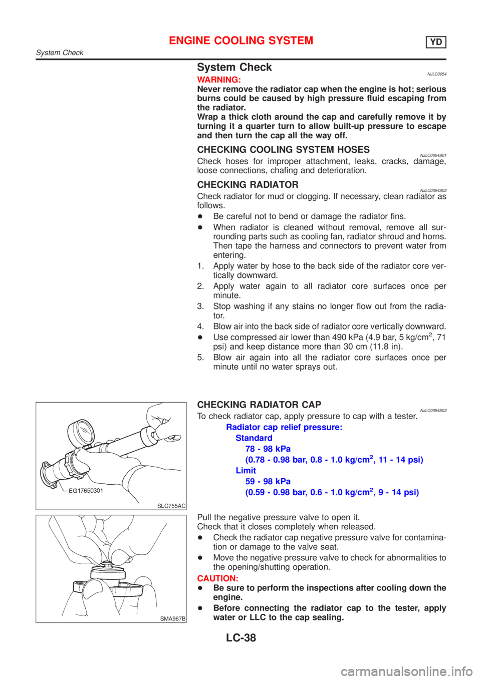
CHECKING RADIATOR CAPNJLC0054S03To check radiator cap, apply pressure to cap with a tester.
Radiator cap relief pressure:
Standard
78-98kPa
(0.78 - 0.98 bar, 0.8 - 1.0 kg/cm
2, 11 - 14 psi)
Limit
59-98kPa
(0.59 - 0.98 bar, 0.6 - 1.0 kg/cm
2,9-14psi)
SMA967B
Pull the negative pressure valve to open it.
Check that it closes completely when released.
+Check the radiator cap negative pressure valve for contamina-
tion or damage to the valve seat.
+Move the negative pressure valve to check for abnormalities to
the opening/shutting operation.
CAUTION:
+Be sure to perform the inspections after cooling down the
engine.
+Before connecting the radiator cap to the tester, apply
water or LLC to the cap sealing.
ENGINE COOLING SYSTEMYD
System Check
LC-38