Page 28 of 2898
ªD1º and ª21º Positions=NJAT0013S0203
+Forward one-way clutch
+Forward clutch
+Low one-way clutchRear internal gear is locked to rotate counterclockwise because of the functioning of
these three clutches.
Overrun clutch
engagement conditions
(Engine brake)D
1: Overdrive control switch ªOFFº and throttle opening is less than 3/16
2
1: Always engaged
At D
1and 21positions, engine brake is not activated due to free turning of low one-
way clutch.
SAT377J
OVERALL SYSTEM
Shift Mechanism (Cont'd)
AT-26
Page 368 of 2898
NJAT0120
SAT049K
1. Drain ATF through drain plug.
SAT008D
2. Remove torque converter.
SAT009D
3. Check torque converter one-way clutch using check tool as
shown at left.
a. Insert check tool into the groove of bearing support built into
one-way clutch outer race.
b. While fixing bearing support with check tool, rotate one-way
clutch spline using flat-bladed screwdriver.
c. Check inner race rotates clockwise only. If not, replace torque
converter assembly.
SAT586H
4. Remove oil charging pipe and oil cooler tube.
DISASSEMBLY
AT-366
Page 552 of 2898

+It is not necessary to remove connecting bolt except for
disassembly or replacement of caliper assembly. In this
case, suspend cylinder body with wire so as not to stretch
brake hose.
+Burnish the brake contact surfaces after refinishing or
replacing drums or rotors, after replacing pads or linings,
or if a soft pedal occurs at very low mileage.
Refer to ªBrake Burnishing Procedureº, ªON-VEHICLE
SERVICEº, BR-8.
SBR764E
SBR916C
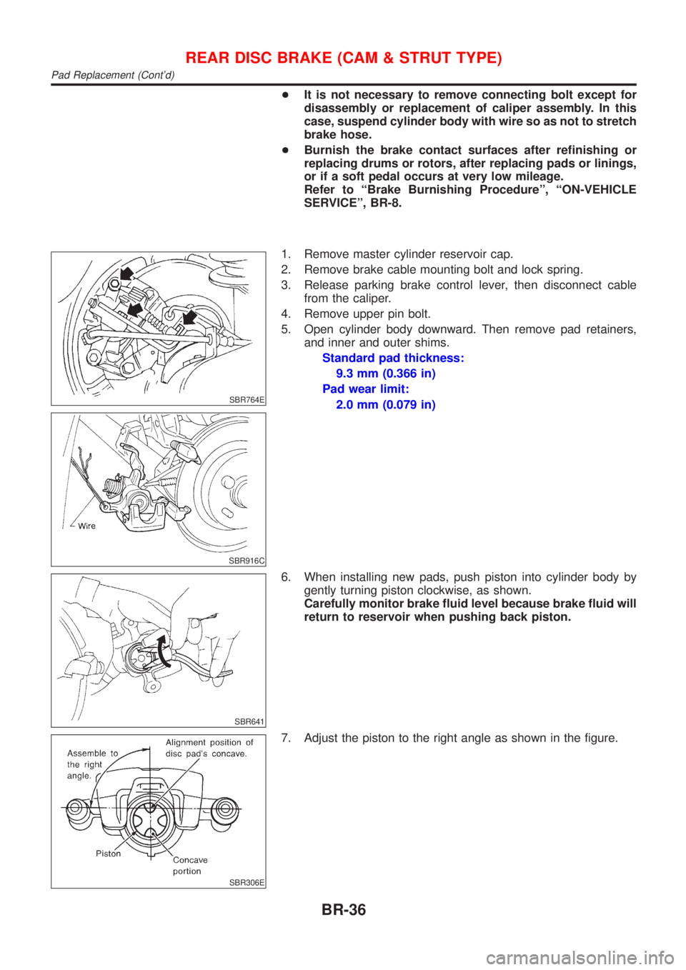
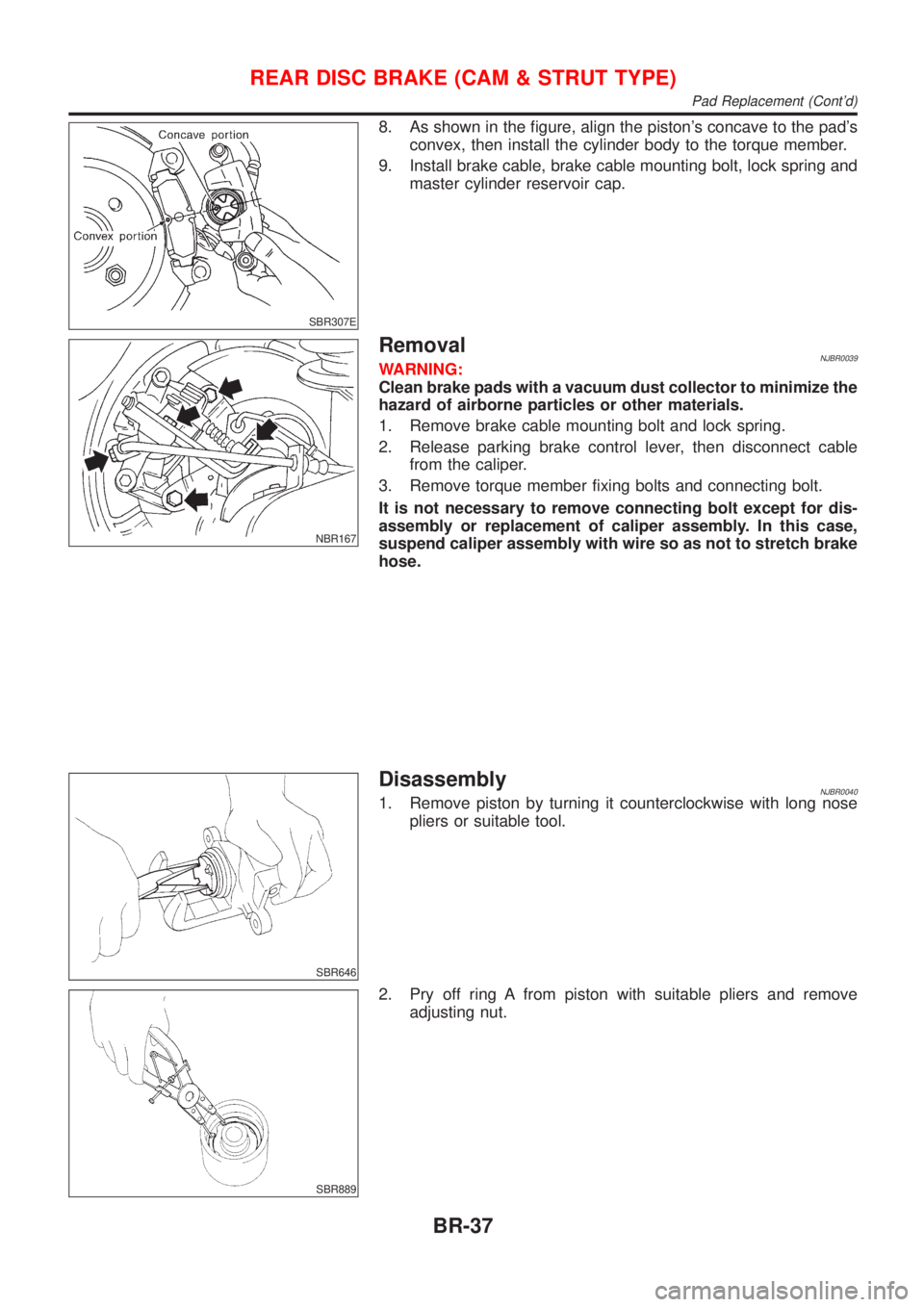
1. Remove master cylinder reservoir cap.
2. Remove brake cable mounting bolt and lock spring.
3. Release parking brake control lever, then disconnect cable
from the caliper.
4. Remove upper pin bolt.
5. Open cylinder body downward. Then remove pad retainers,
and inner and outer shims.
Standard pad thickness:
9.3 mm (0.366 in)
Pad wear limit:
2.0 mm (0.079 in)
SBR641
6. When installing new pads, push piston into cylinder body by
gently turning piston clockwise, as shown.
Carefully monitor brake fluid level because brake fluid will
return to reservoir when pushing back piston.
SBR306E
7. Adjust the piston to the right angle as shown in the figure.
REAR DISC BRAKE (CAM & STRUT TYPE)
Pad Replacement (Cont'd)
BR-36
Page 553 of 2898

SBR307E
8. As shown in the figure, align the piston's concave to the pad's
convex, then install the cylinder body to the torque member.
9. Install brake cable, brake cable mounting bolt, lock spring and
master cylinder reservoir cap.
NBR167
RemovalNJBR0039WARNING:
Clean brake pads with a vacuum dust collector to minimize the
hazard of airborne particles or other materials.
1. Remove brake cable mounting bolt and lock spring.
2. Release parking brake control lever, then disconnect cable
from the caliper.
3. Remove torque member fixing bolts and connecting bolt.
It is not necessary to remove connecting bolt except for dis-
assembly or replacement of caliper assembly. In this case,
suspend caliper assembly with wire so as not to stretch brake
hose.
SBR646
DisassemblyNJBR00401. Remove piston by turning it counterclockwise with long nose
pliers or suitable tool.
SBR889
2. Pry off ring A from piston with suitable pliers and remove
adjusting nut.
REAR DISC BRAKE (CAM & STRUT TYPE)
Pad Replacement (Cont'd)
BR-37
Page 557 of 2898
SBR892
6. Install cup in the specified direction.
SBR755E
7. Install adjuster, bearing, washers and ring A with a suitable
tool.
SBR646
8. Insert piston seal into groove on cylinder body.
9. With piston boot fitted to piston, insert piston boot into groove
on cylinder body and fit piston by turning it clockwise with long
nose pilers, or suitable tool.
SBR767E
10. Fit toggle lever, return spring and cable guide.
SBR306E
11. Adjust the piston to the right angle as shown in the figure.
REAR DISC BRAKE (CAM & STRUT TYPE)
Assembly (Cont'd)
BR-41
Page 560 of 2898
NBR423
1. Remove master cylinder reservoir cap.
2. Remove brake cable lock spring.
3. Release parking brake control lever, then disconnect cable
from the caliper.
4. Remove upper pin bolt.
NBR426
5. Open cylinder body downward. Then remove pads inner and
outer shims.
Standard pad thickness:
9.3 mm (0.366 in)
Pad wear limit:
2.0 mm (0.079 in)
SBR641
6. When installing new pads, push piston into cylinder body by
gently turning piston clockwise, as shown.
Carefully monitor brake fluid level because brake fluid will
return to reservoir when pushing back piston.
NBR374
7. Adjust the piston to the right angle as shown in the figure.
NBR375
8. As shown in the figure, align the piston's concave to the pad's
convex, then install the cylinder body to the torque member.
9. Install brake cable, brake cable mounting bolt, lock spring and
master cylinder reservoir cap.
REAR DISC BRAKE (BALL & RAMP TYPE)
Pad Replacement (Cont'd)
BR-44
Page 829 of 2898
12 ADJUSTMENT THROTTLE POSITION SWITCH CLOSED POSITION-I
With CONSULT-II
1. Loosen throttle position sensor fixing bolts.
2. Confirm that proper vacuum is applied. Refer to test No. 10. During adjustment, vacuum should be applied.
3. Insert 0.05 mm (0.0020 in) feeler gauge between stopper and throttle drum as shown in the figure.
SEF073X
4. Turn throttle position sensor body counterclockwise until ªCLSD THL/P SWº signal switches to ªOFFº.
SEF863Y
©GO TO 13.
TROUBLE DIAGNOSIS Ð BASIC INSPECTIONQG
Basic Inspection/Sedan (Cont'd)
EC-105
Page 830 of 2898
13 ADJUSTMENT THROTTLE POSITION SWITCH CLOSED POSITION-II
With CONSULT-II
1. Temporarily tighten sensor body fixing bolts as follows.
+Gradually move the sensor body clockwise and stop it when ªCLSD THL/P SWº signal switches from ªOFFº to
ªONº, then temporarily tighten sensor body fixing bolts.
SEF964W
2. Make sure two or three times that the signal is ªONº when the throttle valve is closed and ªOFFº when it is opened.
3. Remove 0.05 mm (0.0020 in) feeler gauge then insert 0.15 mm (0.0059 in) feeler gauge.
4. Make sure two or three times that the signal remains ªOFFº when the throttle valve is closed.
5. Tighten throttle position sensor.
6. Check the ªCLSD THL/P SWº signal again.
SEF716Y
The signal remains ªOFFº while closing throttle valve.
OK or NG
OK©GO TO 14.
NG©GO TO 12.
TROUBLE DIAGNOSIS Ð BASIC INSPECTIONQG
Basic Inspection/Sedan (Cont'd)
EC-106