2001 NISSAN ALMERA clock
[x] Cancel search: clockPage 1340 of 2898
JEF344Y
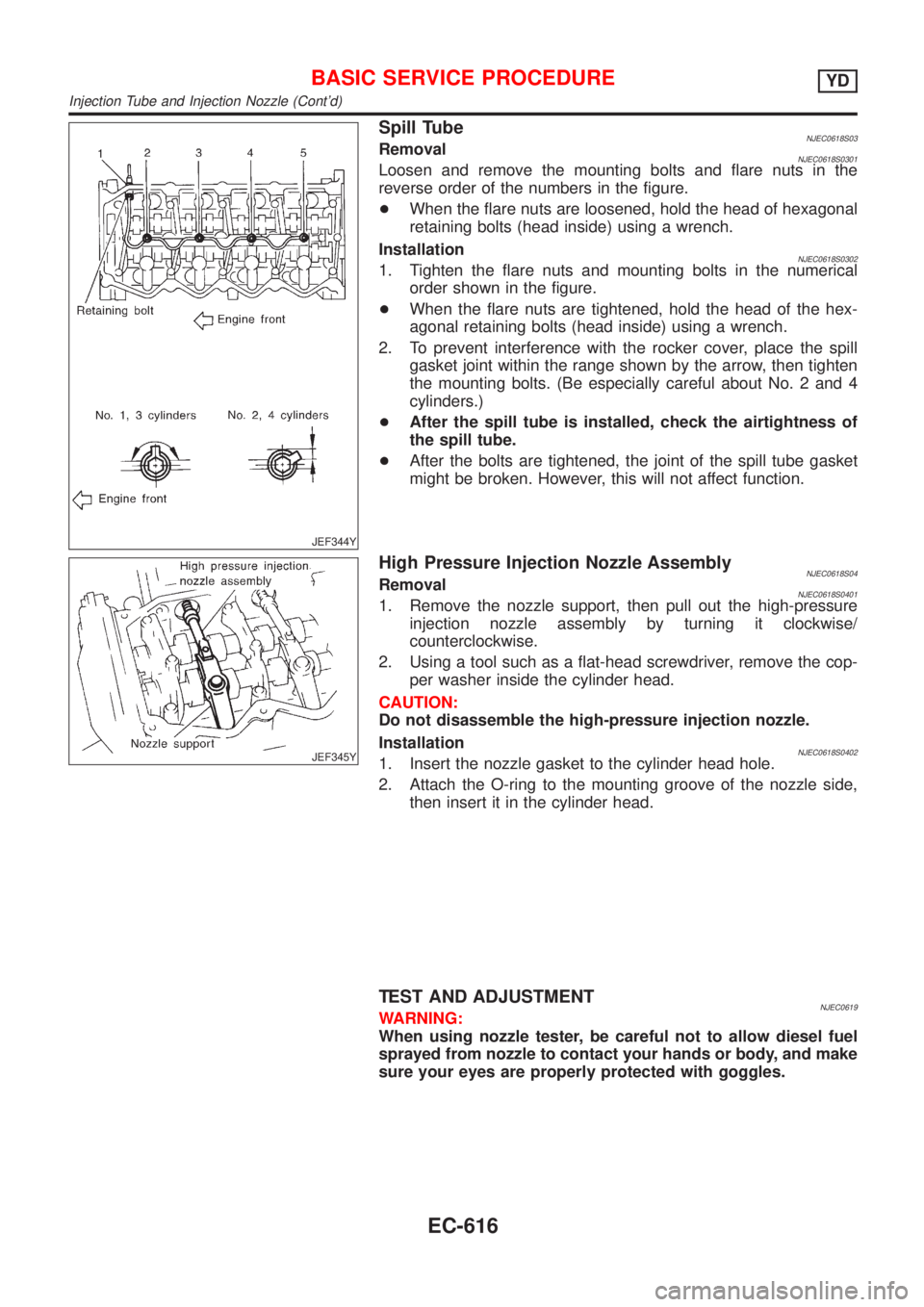
Spill TubeNJEC0618S03RemovalNJEC0618S0301Loosen and remove the mounting bolts and flare nuts in the
reverse order of the numbers in the figure.
+When the flare nuts are loosened, hold the head of hexagonal
retaining bolts (head inside) using a wrench.
Installation
NJEC0618S03021. Tighten the flare nuts and mounting bolts in the numerical
order shown in the figure.
+When the flare nuts are tightened, hold the head of the hex-
agonal retaining bolts (head inside) using a wrench.
2. To prevent interference with the rocker cover, place the spill
gasket joint within the range shown by the arrow, then tighten
the mounting bolts. (Be especially careful about No. 2 and 4
cylinders.)
+After the spill tube is installed, check the airtightness of
the spill tube.
+After the bolts are tightened, the joint of the spill tube gasket
might be broken. However, this will not affect function.
JEF345Y
High Pressure Injection Nozzle AssemblyNJEC0618S04RemovalNJEC0618S04011. Remove the nozzle support, then pull out the high-pressure
injection nozzle assembly by turning it clockwise/
counterclockwise.
2. Using a tool such as a flat-head screwdriver, remove the cop-
per washer inside the cylinder head.
CAUTION:
Do not disassemble the high-pressure injection nozzle.
Installation
NJEC0618S04021. Insert the nozzle gasket to the cylinder head hole.
2. Attach the O-ring to the mounting groove of the nozzle side,
then insert it in the cylinder head.
TEST AND ADJUSTMENTNJEC0619WARNING:
When using nozzle tester, be careful not to allow diesel fuel
sprayed from nozzle to contact your hands or body, and make
sure your eyes are properly protected with goggles.
BASIC SERVICE PROCEDUREYD
Injection Tube and Injection Nozzle (Cont'd)
EC-616
Page 1343 of 2898
JEF351Y
2. Disconnect the fuel hoses from the fuel injection pump.
3. Disconnect the harness connector from the fuel injection
pump.
+Disconnect the connector by pulling the connector stopper
fully.
+When the stopper is fully pulled, the connector will be discon-
nected together. For installation, push the connector half way
first, then press the stopper until it locks, so that the connec-
tor is connected together.
4. Remove the fuel injection pump rear bracket.
JEF352Y
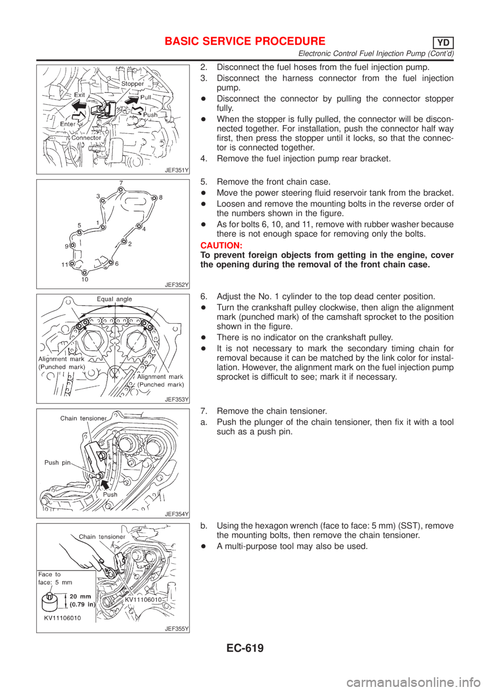
5. Remove the front chain case.
+Move the power steering fluid reservoir tank from the bracket.
+Loosen and remove the mounting bolts in the reverse order of
the numbers shown in the figure.
+As for bolts 6, 10, and 11, remove with rubber washer because
there is not enough space for removing only the bolts.
CAUTION:
To prevent foreign objects from getting in the engine, cover
the opening during the removal of the front chain case.
JEF353Y
6. Adjust the No. 1 cylinder to the top dead center position.
+Turn the crankshaft pulley clockwise, then align the alignment
mark (punched mark) of the camshaft sprocket to the position
shown in the figure.
+There is no indicator on the crankshaft pulley.
+It is not necessary to mark the secondary timing chain for
removal because it can be matched by the link color for instal-
lation. However, the alignment mark on the fuel injection pump
sprocket is difficult to see; mark it if necessary.
JEF354Y
7. Remove the chain tensioner.
a. Push the plunger of the chain tensioner, then fix it with a tool
such as a push pin.
JEF355Y
b. Using the hexagon wrench (face to face: 5 mm) (SST), remove
the mounting bolts, then remove the chain tensioner.
+A multi-purpose tool may also be used.
BASIC SERVICE PROCEDUREYD
Electronic Control Fuel Injection Pump (Cont'd)
EC-619
Page 1424 of 2898
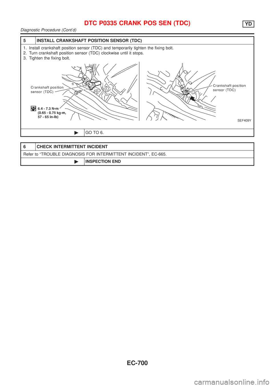
5 INSTALL CRANKSHAFT POSITION SENSOR (TDC)
1. Install crankshaft position sensor (TDC) and temporarily tighten the fixing bolt.
2. Turn crankshaft position sensor (TDC) clockwise until it stops.
3. Tighten the fixing bolt.
SEF409Y
©GO TO 6.
6 CHECK INTERMITTENT INCIDENT
Refer to ªTROUBLE DIAGNOSIS FOR INTERMITTENT INCIDENTº, EC-665.
©INSPECTION END
DTC P0335 CRANK POS SEN (TDC)YD
Diagnostic Procedure (Cont'd)
EC-700
Page 1560 of 2898
Wiring Diagram - ROOM/L -/Sedan With Interior
Room Lamp Timer ................................................... 117
Trouble Diagnoses/Sedan With Interior Room
Lamp Timer .............................................................. 119
System Description/Hatchback With Interior
Room Lamp Timer ...................................................127
Wiring Diagram - ROOM/L -/Hatchback With
Interior Room Lamp Timer.......................................129
Trouble Diagnoses/Hatchback With Interior
Room Lamp Timer ...................................................131
Wiring Diagram - ROOM/L -/Sedan Without
Timer ........................................................................139
Wiring Diagram - ROOM/L -/Hatchback Without
Timer ........................................................................140
SPOT AND TRUNK ROOM LAMPS...........................141
Wiring Diagram - INT/L -/Sedan ..............................141
Wiring Diagram - INT/L -/Hatchback .......................143
METERS AND GAUGES.............................................144
Component Parts and Harness Connector
Location/Sedan ........................................................144
System Description/Sedan ......................................144
Combination Meter/Sedan With Tachometer...........146
Schematic/Sedan With Tachometer ........................147
Combination Meter/Without Tachometer .................148
Schematic/Without Tachometer ...............................149
Construction/Sedan .................................................150
Wiring Diagram - METER -/Without Tachometer ....151
Wiring Diagram - METER -/Sedan ..........................152
Meter/Gauge Operation and Odo/Trip Meter
Segment Check in Diagnosis Mode/Sedan.............153
Trouble Diagnoses/Sedan .......................................154
Electrical Components Inspection/Sedan ................162
Component Parts and Harness Connector
Location/Hatchback .................................................164
System Description/Hatchback ................................164
Combination Meter/Hatchback (Models before
VIN No. - N16U0135126) ........................................166
Combination Meter/Hatchback (Models after VIN
No. - N16U0135126) ...............................................167
Schematic/Hatchback (Models before VIN No. -
N160135126) ...........................................................168
Schematic/Hatchback (Models after VIN No. -
N16U0135126).........................................................169
Construction/Hatchback ...........................................170
Wiring Diagram - METER -/Hatchback ...................171
Combination Meter Self-Diagnosis/Hatchback ........173
Trouble Diagnoses/Hatchback.................................176
Electrical Components Inspection/Hatchback .........183
WARNING LAMPS......................................................184
Schematic/Sedan .....................................................184
Wiring Diagram - WARN -/Sedan ............................185
Schematic/Hatchback ..............................................189Wiring Diagram - WARN -/Hatchback .....................190
Electrical Components Inspection ...........................194
A/T INDICATOR...........................................................195
Wiring Diagram - AT/IND -/With Tachometer...........195
Wiring Diagram - AT/IND -/Without Tachometer......196
WARNING CHIME.......................................................197
Component Parts and Harness Connector
Location/Sedan ........................................................197
System Description/Sedan ......................................198
Wiring Diagram - CHIME -/Sedan ...........................199
Trouble Diagnoses/Sedan .......................................200
Component Parts and Harness Connector
Location/Hatchback .................................................205
System Description/Hatchback ................................206
Wiring Diagram - CHIME -/Hatchback ....................207
Trouble Diagnoses/Hatchback.................................209
FRONT WIPER AND WASHER..................................215
System Description/Sedan ......................................215
Wiring Diagram - WIPER -/Sedan ...........................217
System Description/Hatchback ................................218
Wiring Diagram - WIPER -/Hatchback ....................220
Removal and Installation .........................................222
Washer Nozzle Adjustment .....................................223
Washer Tube Layout ...............................................224
REAR WIPER AND WASHER....................................225
Wiring Diagram - WIP/R -/Sedan ............................225
Wiring Diagram - WIP/R -/Hatchback......................227
Removal and Installation .........................................229
Washer Nozzle Adjustment .....................................229
Washer Tube Layout ...............................................230
HEADLAMP WASHER................................................231
Wiring Diagram - HLC -/Sedan ...............................231
Wiring Diagram - HLC -/Hatchback .........................232
Washer Tube Layout ...............................................233
HORN...........................................................................234
Wiring Diagram - HORN -/Sedan ............................234
Wiring Diagram - HORN -/Hatchback .....................235
CIGARETTE LIGHTER................................................236
Wiring Diagram - CIGAR -/Sedan ...........................236
Wiring Diagram - CIGAR -/Hatchback.....................237
CLOCK.........................................................................238
Wiring Diagram - CLOCK -/Sedan ..........................238
Wiring Diagram - CLOCK -/Hatchback....................239
REAR WINDOW DEFOGGER.....................................240
System Description/Sedan ......................................240
Wiring Diagram - DEF -/Sedan ...............................242
Trouble Diagnoses/Sedan .......................................246
System Description/Hatchback ................................249
Wiring Diagram - DEF -/Hatchback .........................250
Trouble Diagnoses/Hatchback.................................252
Electrical Components Inspection ...........................255
Filament Check ........................................................256
CONTENTS(Cont'd)
EL-2
Page 1796 of 2898
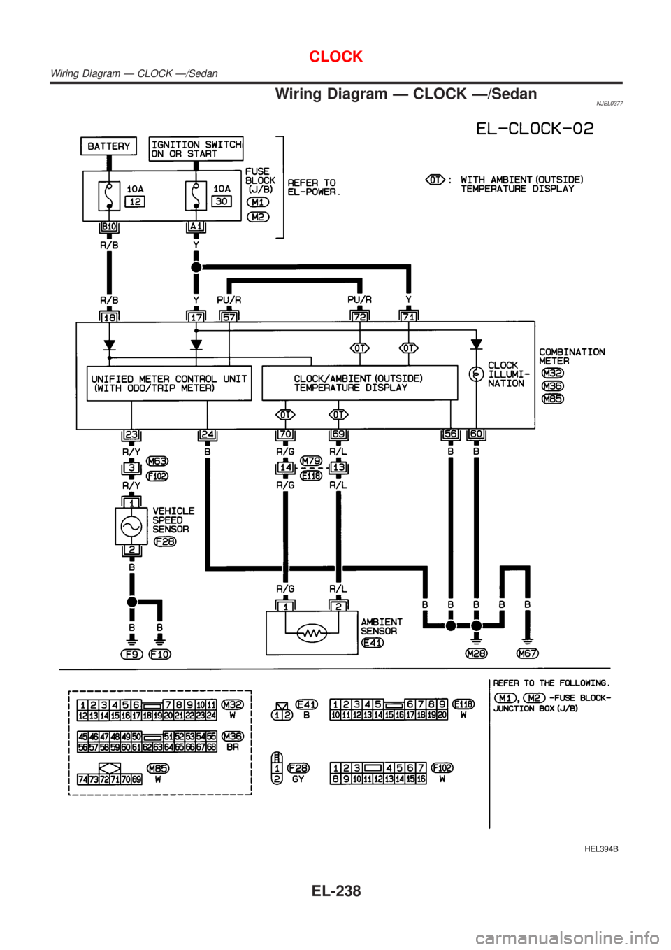
Wiring Diagram Ð CLOCK Ð/SedanNJEL0377
HEL394B
CLOCK
Wiring Diagram Ð CLOCK Ð/Sedan
EL-238
Page 1797 of 2898
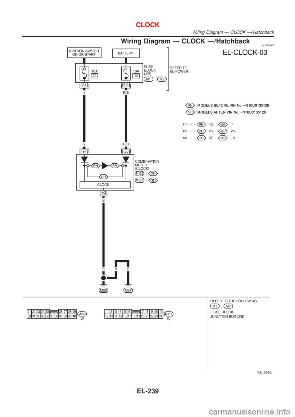
Wiring Diagram Ð CLOCK Ð/HatchbackNJEL0462
YEL366C
CLOCK
Wiring Diagram Ð CLOCK Ð/Hatchback
EL-239
Page 2039 of 2898
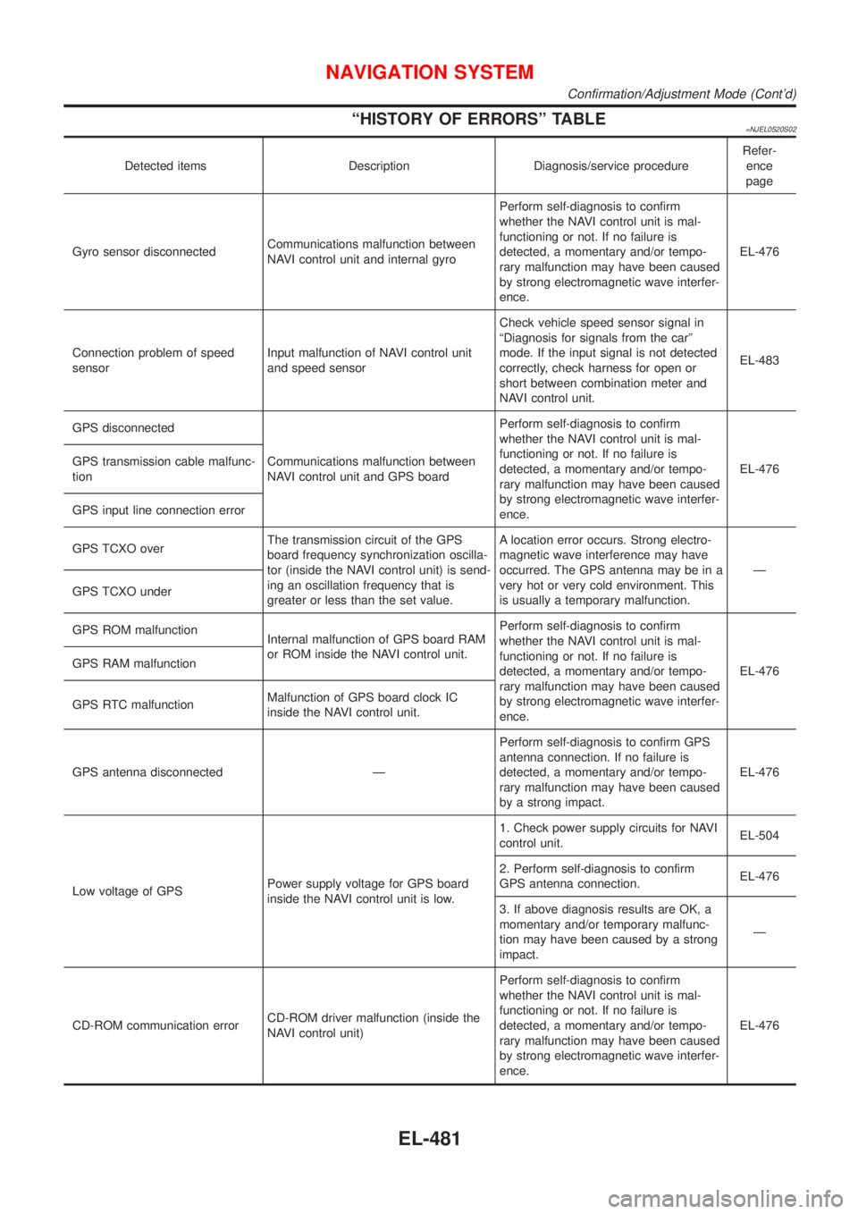
ªHISTORY OF ERRORSº TABLE=NJEL0520S02
Detected items Description Diagnosis/service procedureRefer-
ence
page
Gyro sensor disconnectedCommunications malfunction between
NAVI control unit and internal gyroPerform self-diagnosis to confirm
whether the NAVI control unit is mal-
functioning or not. If no failure is
detected, a momentary and/or tempo-
rary malfunction may have been caused
by strong electromagnetic wave interfer-
ence.EL-476
Connection problem of speed
sensorInput malfunction of NAVI control unit
and speed sensorCheck vehicle speed sensor signal in
ªDiagnosis for signals from the carº
mode. If the input signal is not detected
correctly, check harness for open or
short between combination meter and
NAVI control unit.EL-483
GPS disconnected
Communications malfunction between
NAVI control unit and GPS boardPerform self-diagnosis to confirm
whether the NAVI control unit is mal-
functioning or not. If no failure is
detected, a momentary and/or tempo-
rary malfunction may have been caused
by strong electromagnetic wave interfer-
ence.EL-476 GPS transmission cable malfunc-
tion
GPS input line connection error
GPS TCXO overThe transmission circuit of the GPS
board frequency synchronization oscilla-
tor (inside the NAVI control unit) is send-
ing an oscillation frequency that is
greater or less than the set value.A location error occurs. Strong electro-
magnetic wave interference may have
occurred. The GPS antenna may be in a
very hot or very cold environment. This
is usually a temporary malfunction.Ð
GPS TCXO under
GPS ROM malfunction
Internal malfunction of GPS board RAM
or ROM inside the NAVI control unit.Perform self-diagnosis to confirm
whether the NAVI control unit is mal-
functioning or not. If no failure is
detected, a momentary and/or tempo-
rary malfunction may have been caused
by strong electromagnetic wave interfer-
ence.EL-476 GPS RAM malfunction
GPS RTC malfunctionMalfunction of GPS board clock IC
inside the NAVI control unit.
GPS antenna disconnected ÐPerform self-diagnosis to confirm GPS
antenna connection. If no failure is
detected, a momentary and/or tempo-
rary malfunction may have been caused
by a strong impact.EL-476
Low voltage of GPSPower supply voltage for GPS board
inside the NAVI control unit is low.1. Check power supply circuits for NAVI
control unit.EL-504
2. Perform self-diagnosis to confirm
GPS antenna connection.EL-476
3. If above diagnosis results are OK, a
momentary and/or temporary malfunc-
tion may have been caused by a strong
impact.Ð
CD-ROM communication errorCD-ROM driver malfunction (inside the
NAVI control unit)Perform self-diagnosis to confirm
whether the NAVI control unit is mal-
functioning or not. If no failure is
detected, a momentary and/or tempo-
rary malfunction may have been caused
by strong electromagnetic wave interfer-
ence.EL-476
NAVIGATION SYSTEM
Confirmation/Adjustment Mode (Cont'd)
EL-481
Page 2133 of 2898
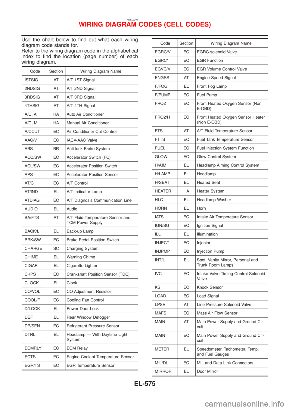
NJEL0311
Use the chart below to find out what each wiring
diagram code stands for.
Refer to the wiring diagram code in the alphabetical
index to find the location (page number) of each
wiring diagram.
Code Section Wiring Diagram Name
ISTSIG AT A/T 1ST Signal
2NDSIG AT A/T 2ND Signal
3RDSIG AT A/T 3RD Signal
4THSIG AT A/T 4TH Signal
A/C, A HA Auto Air Conditioner
A/C, M HA Manual Air Conditioner
A/CCUT EC Air Conditioner Cut Control
AAC/V EC IACV-AAC Valve
ABS BR Anti-lock Brake System
ACC/SW EC Accelerator Switch (FC)
ACL/SW EC Accelerator Position Switch
APS EC Accelerator Position Sensor
AT/C EC A/T Control
AT/IND EL A/T Indicator Lamp
ATDIAG EC A/T Diagnosis Communication Line
AUDIO EL Audio
BA/FTS AT A/T Fluid Temperature Sensor and
TCM Power Supply
BACK/L EL Back-up Lamp
BRK/SW EC Brake Pedal Position Switch
CHARGE SC Charging System
CHIME EL Warning Chime
CIGAR EL Cigarette Lighter
CKPS EC Crankshaft Position Sensor (TDC)
CLOCK EL Clock
CO/VOL EC CO Adjustment Resistor
COOL/F EC Cooling Fan Control
D/LOCK EL Power Door Lock
DEF EL Rear Window Defogger
DP/SEN EC Refrigerant Pressure Sensor
DTRL EL Headlamp Ð With Daytime Light
System
ECMRLY EC ECM Relay
ECTS EC Engine Coolant Temperature Sensor
EGR/TS EC EGR Temperature Sensor
Code Section Wiring Diagram Name
EGRC/V EC EGRC-solenoid Valve
EGRC1 EC EGR Function
EGVC/V EC EGR Volume Control Valve
ENGSS AT Engine Speed Signal
F/FOG EL Front Fog Lamp
F/PUMP EC Fuel Pump
FRO2 EC Front Heated Oxygen Sensor (Non
E-OBD)
FRO2/H EC Front Heated Oxygen Sensor Heater
(Non E-OBD)
FTS AT A/T Fluid Temperature Sensor
FTTS EC Fuel Tank Temperature Sensor
FUEL EC Fuel Injection System Function
GLOW EC Glow Control System
H/AIM EL Headlamp Aiming Control System
H/LAMP EL Headlamp
H/SEAT EL Heated Seat
HEATER HA Heater System
HLC EL Headlamp Washer
HORN EL Horn
IATS EC Intake Air Temperature Sensor
IGN/SG EC Ignition Signal
ILL EL Illumination
INJECT EC Injector
INJPMP EC Injection Pump
INT/L EL Spot, Vanity Mirror, Personal and
Trunk Room Lamps
IVC EC Intake Valve Timing Control Solenoid
Valve
KS EC Knock Sensor
LOAD EC Load Signal
LPSV AT Line Pressure Solenoid Valve
MAFS EC Mass Air Flow Sensor
MAIN AT Main Power Supply and Ground Cir-
cuit
MAIN EC Main Power Supply and Ground Cir-
cuit
METER EL Speedometer, Tachometer, Temp.
and Fuel Gauges
MIL/DL EC MIL and Data Link Connectors
MIRROR EL Door Mirror
WIRING DIAGRAM CODES (CELL CODES)
EL-575