2001 NISSAN ALMERA steering
[x] Cancel search: steeringPage 352 of 2898
SAT854J
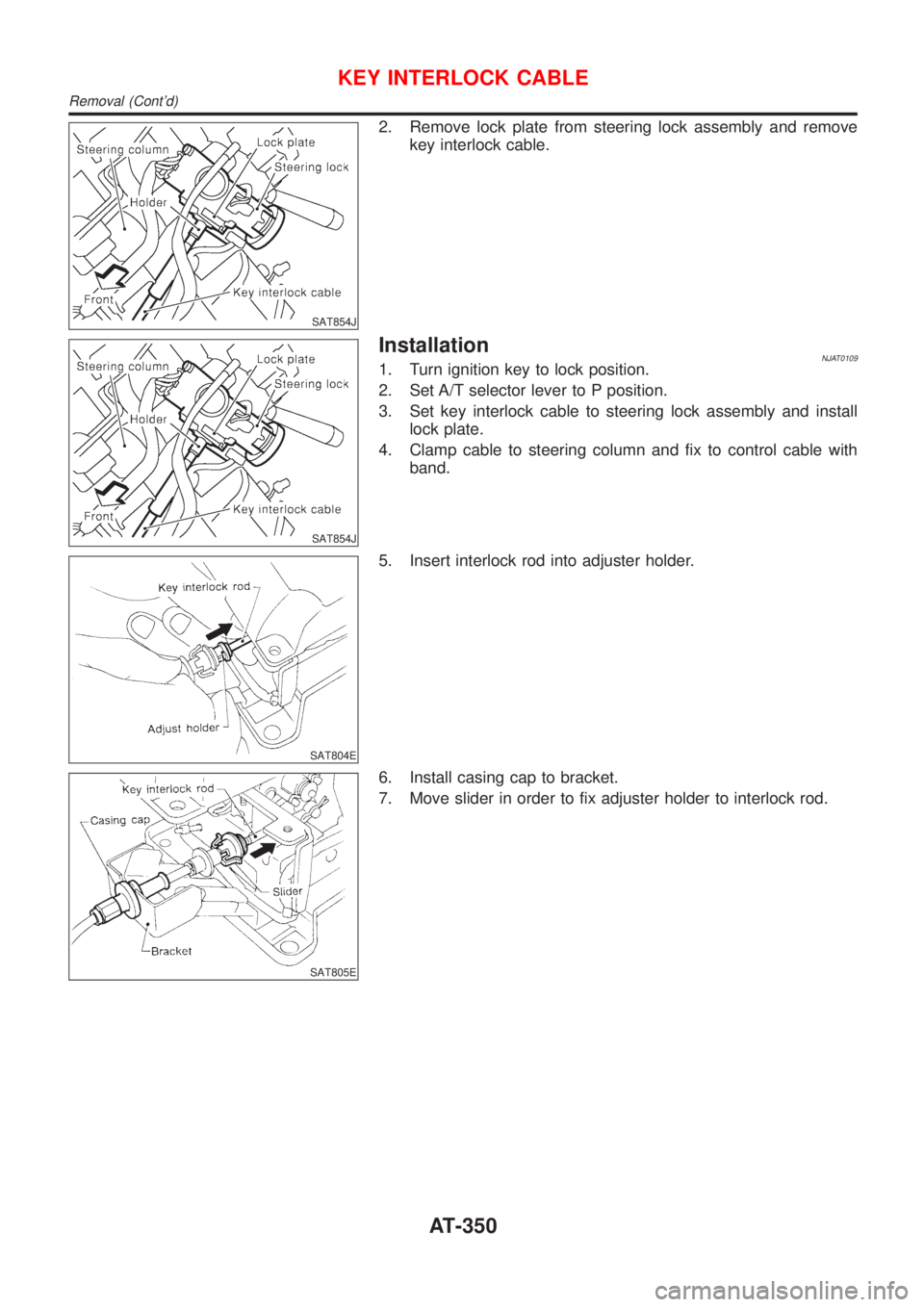
2. Remove lock plate from steering lock assembly and remove
key interlock cable.
SAT854J
InstallationNJAT01091. Turn ignition key to lock position.
2. Set A/T selector lever to P position.
3. Set key interlock cable to steering lock assembly and install
lock plate.
4. Clamp cable to steering column and fix to control cable with
band.
SAT804E
5. Insert interlock rod into adjuster holder.
SAT805E
6. Install casing cap to bracket.
7. Move slider in order to fix adjuster holder to interlock rod.
KEY INTERLOCK CABLE
Removal (Cont'd)
AT-350
Page 491 of 2898
Noise, Vibration and Harshness (NVH)
Troubleshooting
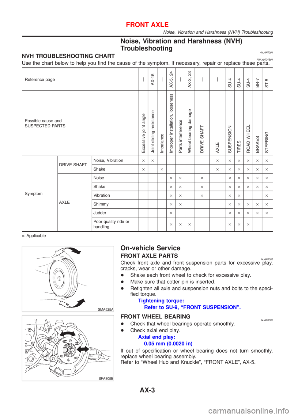
=NJAX0004NVH TROUBLESHOOTING CHARTNJAX0004S01Use the chart below to help you find the cause of the symptom. If necessary, repair or replace these parts.
Reference pageÐ
AX-15
Ð
AX-5, 24
Ð
AX-3, 23
Ð
Ð
SU-4
SU-4
SU-4
BR-7
ST-5
Possible cause and
SUSPECTED PARTS
Excessive joint angle
Joint sliding resistance
Imbalance
Improper installation, looseness
Parts interference
Wheel bearing damage
DRIVE SHAFT
AXLE
SUSPENSION
TIRES
ROAD WHEEL
BRAKES
STEERING
SymptomDRIVE SHAFTNoise, Vibration´´ ´ ´´´´´
Shake´ ´ ´ ´´´´´
AXLENoise´´ ´ ´´´´´
Shake´´ ´ ´´´´´
Vibration´´ ´ ´´ ´
Shimmy´´ ´´´´´
Judder´ ´´´´´
Poor quality ride or
handling´´´ ´´´
´: Applicable
SMA525A
On-vehicle Service
FRONT AXLE PARTSNJAX0005Check front axle and front suspension parts for excessive play,
cracks, wear or other damage.
+Shake each front wheel to check for excessive play.
+Make sure that cotter pin is inserted.
+Retighten all axle and suspension nuts and bolts to the speci-
fied torque.
Tightening torque:
Refer to SU-9, ªFRONT SUSPENSIONº.
SFA805B
FRONT WHEEL BEARINGNJAX0006+Check that wheel bearings operate smoothly.
+Check axial end play.
Axial end play:
0.05 mm (0.0020 in)
If out of specification or wheel bearing does not turn smoothly,
replace wheel bearing assembly.
Refer to ªWheel Hub and Knuckleº, ªFRONT AXLEº, AX-5.
FRONT AXLE
Noise, Vibration and Harshness (NVH) Troubleshooting
AX-3
Page 496 of 2898
SAX008
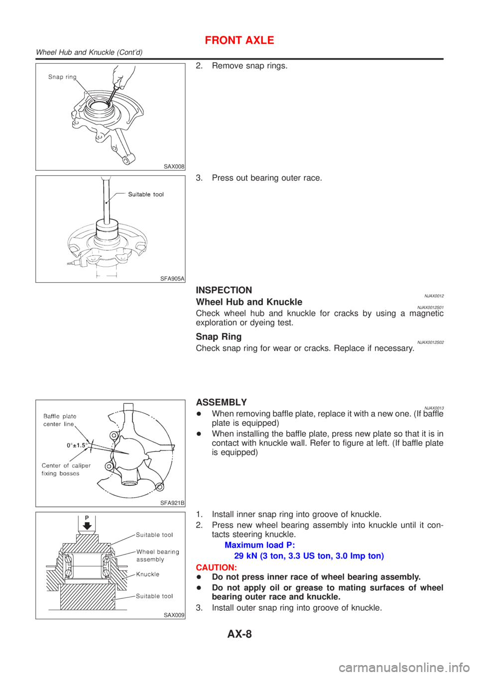
2. Remove snap rings.
SFA905A
3. Press out bearing outer race.
INSPECTIONNJAX0012Wheel Hub and KnuckleNJAX0012S01Check wheel hub and knuckle for cracks by using a magnetic
exploration or dyeing test.
Snap RingNJAX0012S02Check snap ring for wear or cracks. Replace if necessary.
SFA921B
ASSEMBLYNJAX0013+When removing baffle plate, replace it with a new one. (If baffle
plate is equipped)
+When installing the baffle plate, press new plate so that it is in
contact with knuckle wall. Refer to figure at left. (If baffle plate
is equipped)
SAX009
1. Install inner snap ring into groove of knuckle.
2. Press new wheel bearing assembly into knuckle until it con-
tacts steering knuckle.
Maximum load P:
29 kN (3 ton, 3.3 US ton, 3.0 Imp ton)
CAUTION:
+Do not press inner race of wheel bearing assembly.
+Do not apply oil or grease to mating surfaces of wheel
bearing outer race and knuckle.
3. Install outer snap ring into groove of knuckle.
FRONT AXLE
Wheel Hub and Knuckle (Cont'd)
AX-8
Page 523 of 2898
NJBR0005
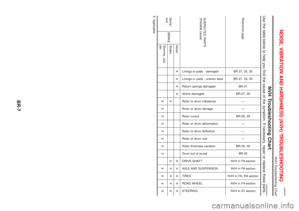
NVH Troubleshooting ChartNJBR0005S01Use the table below to help you find the cause of the symptom. If necessary, repair or replace these parts.
Reference page
BR-27, 33, 35
BR-27, 33, 35
BR-31
BR-27, 35
Ð
Ð
BR-29, 39
Ð
Ð
Ð
BR-29, 39
BR-33
NVH in FA section
NVH in FA section
NVH in FA, RA section
NVH in FA section
NVH in ST section
SUSPECTED PARTS
(Possible cause)
Linings or pads - damaged
Linings or pads - uneven wear
Return springs damaged
Shims damaged
Rotor or drum imbalance
Rotor or drum damage
Rotor runout
Rotor or drum deformation
Rotor or drum deflection
Rotor or drum rust
Rotor thickness variation
Drum out of round
DRIVE SHAFT
AXLE AND SUSPENSION
TIRES
ROAD WHEEL
STEERING
Symp-
tomBRAKENoiseXXXX XXXXX
Shake XXXXXX
Shimmy, Jud-
derXXXXXXXX XXXX
X: Applicable
NOISE, VIBRATION AND HARSHNESS (NVH) TROUBLESHOOTING
NVH Troubleshooting Chart
BR-7
Page 565 of 2898
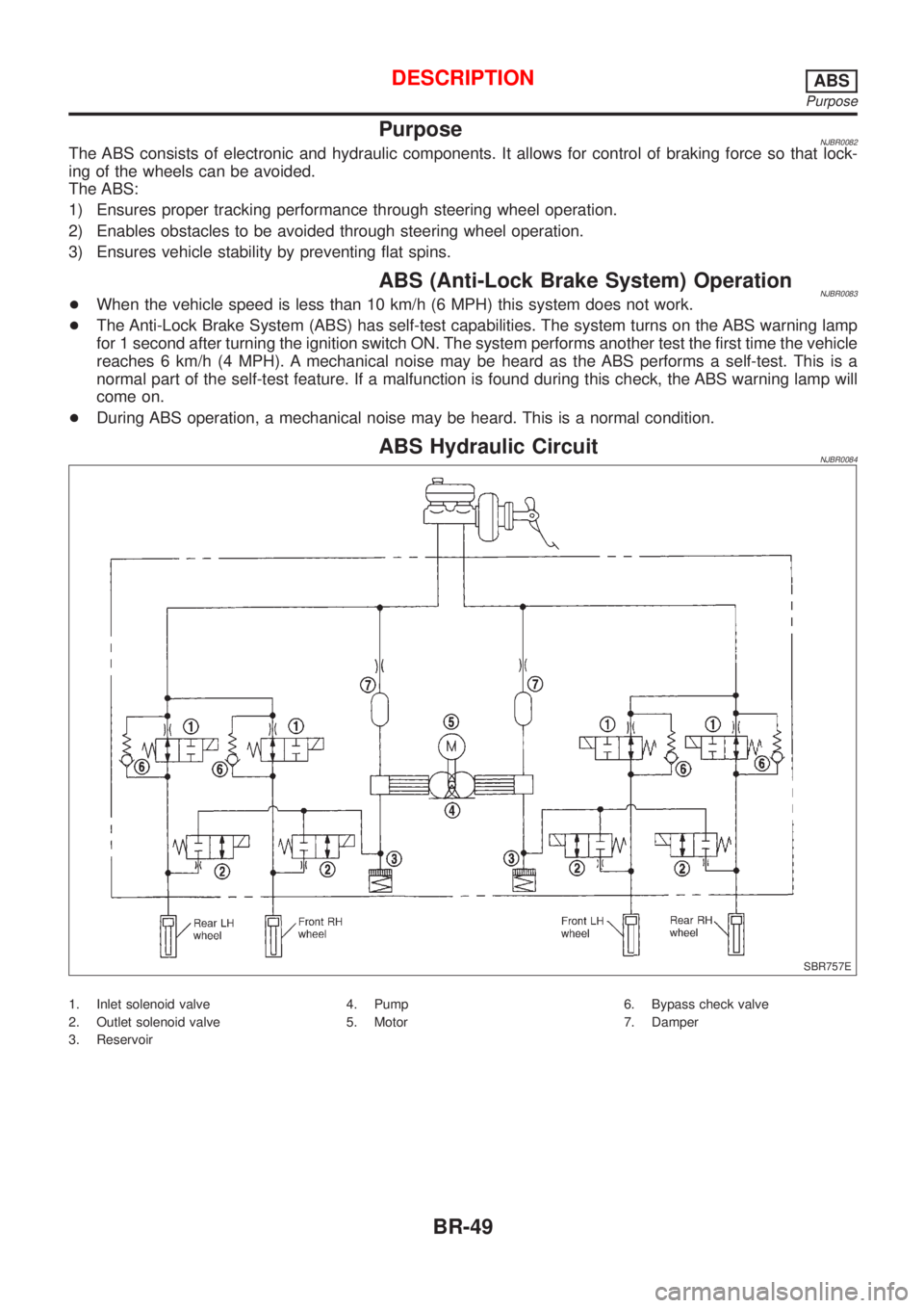
PurposeNJBR0082The ABS consists of electronic and hydraulic components. It allows for control of braking force so that lock-
ing of the wheels can be avoided.
The ABS:
1) Ensures proper tracking performance through steering wheel operation.
2) Enables obstacles to be avoided through steering wheel operation.
3) Ensures vehicle stability by preventing flat spins.
ABS (Anti-Lock Brake System) OperationNJBR0083+When the vehicle speed is less than 10 km/h (6 MPH) this system does not work.
+The Anti-Lock Brake System (ABS) has self-test capabilities. The system turns on the ABS warning lamp
for 1 second after turning the ignition switch ON. The system performs another test the first time the vehicle
reaches 6 km/h (4 MPH). A mechanical noise may be heard as the ABS performs a self-test. This is a
normal part of the self-test feature. If a malfunction is found during this check, the ABS warning lamp will
come on.
+During ABS operation, a mechanical noise may be heard. This is a normal condition.
ABS Hydraulic CircuitNJBR0084
SBR757E
1. Inlet solenoid valve
2. Outlet solenoid valve
3. Reservoir4. Pump
5. Motor6. Bypass check valve
7. Damper
DESCRIPTIONABS
Purpose
BR-49
Page 709 of 2898
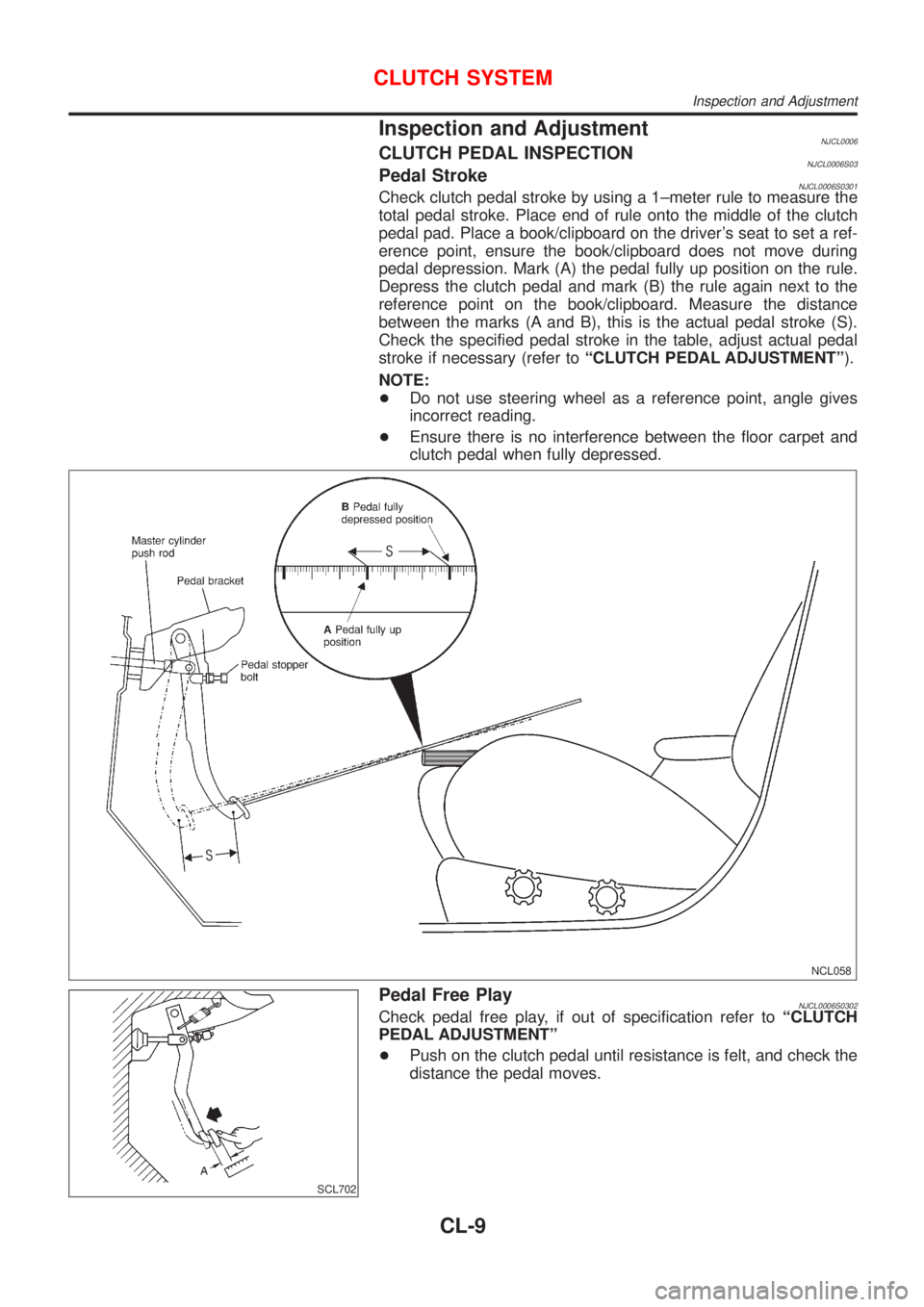
Inspection and AdjustmentNJCL0006CLUTCH PEDAL INSPECTIONNJCL0006S03Pedal StrokeNJCL0006S0301Check clutch pedal stroke by using a 1±meter rule to measure the
total pedal stroke. Place end of rule onto the middle of the clutch
pedal pad. Place a book/clipboard on the driver's seat to set a ref-
erence point, ensure the book/clipboard does not move during
pedal depression. Mark (A) the pedal fully up position on the rule.
Depress the clutch pedal and mark (B) the rule again next to the
reference point on the book/clipboard. Measure the distance
between the marks (A and B), this is the actual pedal stroke (S).
Check the specified pedal stroke in the table, adjust actual pedal
stroke if necessary (refer toªCLUTCH PEDAL ADJUSTMENTº).
NOTE:
+Do not use steering wheel as a reference point, angle gives
incorrect reading.
+Ensure there is no interference between the floor carpet and
clutch pedal when fully depressed.
NCL058
SCL702
Pedal Free PlayNJCL0006S0302Check pedal free play, if out of specification refer toªCLUTCH
PEDAL ADJUSTMENTº
+Push on the clutch pedal until resistance is felt, and check the
distance the pedal moves.
CLUTCH SYSTEM
Inspection and Adjustment
CL-9
Page 730 of 2898
Diagnostic Procedure ..............................................487
Component Inspection .............................................490
EGR VOLUME CONTROL SYSTEM (WHERE
FITTED)........................................................................491
Description ...............................................................491
CONSULT-II Reference Value in Data Monitor
Mode ........................................................................492
ECM Terminals and Reference Value .....................493
Wiring Diagram ........................................................494
Diagnostic Procedure ..............................................496
Component Inspection .............................................501
EVAP CANISTER PURGE VOLUME CONTROL
SOLENOID VALVE......................................................503
Description ...............................................................503
CONSULT-II Reference Value in Data Monitor
Mode ........................................................................503
ECM Terminals and Reference Value .....................504
Wiring Diagram ........................................................505
Diagnostic Procedure ..............................................507
Component Inspection .............................................510
IDLE AIR CONTROL VALVE (IACV) - AUXILIARY
AIR CONTROL............................................................ 511
Description ............................................................... 511
CONSULT-II Reference Value in Data Monitor
Mode ........................................................................512
ECM Terminals and Reference Value .....................512
Wiring Diagram ........................................................513
Diagnostic Procedure ..............................................515
Component Inspection .............................................519
CLOSED THROTTLE POSITION SWITCH
(WHERE FITTED)........................................................520
Component Description ...........................................520
ECM Terminals and Reference Value .....................520
Wiring Diagram ........................................................521
Diagnostic Procedure ..............................................522
Component Inspection .............................................525
INTAKE VALVE TIMING CONTROL SOLENOID
VALVE..........................................................................526
Component Description ...........................................526
Operation .................................................................526
CONSULT-II Reference Value in Data Monitor
Mode ........................................................................526
ECM Terminals and Reference Value .....................526
Wiring Diagram ........................................................527
Diagnostic Procedure ..............................................529
Component Inspection .............................................531
A/T COMMUNICATION LINE......................................532
System Description ..................................................532
Wiring Diagram ........................................................533
Diagnostic Procedure ..............................................534
PARK/NEUTRAL POSITION (PNP) SWITCH............536
Component Description ...........................................536CONSULT-II Reference Value in Data Monitor
Mode ........................................................................536
ECM Terminals and Reference Value .....................536
Wiring Diagram ........................................................537
Diagnostic Procedure ..............................................538
INJECTOR...................................................................541
Component Description ...........................................541
CONSULT-II Reference Value in Data Monitor
Mode ........................................................................541
ECM Terminals and Reference Value .....................541
Wiring Diagram ........................................................542
Diagnostic Procedure ..............................................544
Component Inspection .............................................546
IGNITION SIGNAL.......................................................547
Component Description ...........................................547
CONSULT-II Reference Value in Data Monitor
Mode ........................................................................547
ECM Terminals and Reference Value .....................547
Wiring Diagram ........................................................548
Diagnostic Procedure ..............................................551
Component Inspection .............................................555
START SIGNAL...........................................................557
CONSULT-II Reference Value in Data Monitor
Mode ........................................................................557
ECM Terminals and Reference Value .....................557
Wiring Diagram ........................................................558
Diagnostic Procedure ..............................................559
FUEL PUMP.................................................................561
System Description ..................................................561
Component Description ...........................................561
CONSULT-II Reference Value in Data Monitor
Mode ........................................................................561
ECM Terminals and Reference Value .....................562
Wiring Diagram ........................................................563
Diagnostic Procedure ..............................................564
Component Inspection .............................................566
POWER STEERING OIL PRESSURE SWITCH.........567
Component Description ...........................................567
CONSULT-II Reference Value in Data Monitor
Mode ........................................................................567
ECM Terminals and Reference Value .....................567
Wiring Diagram ........................................................568
Diagnostic Procedure ..............................................569
Component Inspection .............................................570
REFRIGERANT PRESSURE SENSOR......................572
Description ...............................................................572
ECM Terminals and Reference Value .....................572
Wiring Diagram ........................................................573
Diagnostic Procedure ..............................................575
ELECTRICAL LOAD SIGNAL.....................................578
CONSULT-II Reference Value in Data Monitor
Mode ........................................................................578
CONTENTS(Cont'd)
EC-6
Page 755 of 2898

System ChartNJEC0013
Input (Sensor) ECM Function Output (Actuator)
+Camshaft position sensor (PHASE)
+Crankshaft position sensor (POS)
+Mass air flow sensor
+Engine coolant temperature sensor
+Heated oxygen sensor 1 (front)
+Ignition switch
+Throttle position sensor
+PNP switch
+Air conditioner switch
+Knock sensor
+EGR temperature sensor*1, *4
+Fuel tank temperature sensor*1, *4
+Battery voltage
+Power steering oil pressure switch
+Vehicle speed sensor
+Intake air temperature sensor
+Heated oxygen sensor 2 (rear)*2
+TCM (Transmission Control Module)*3
+Closed throttle position switch
+Electrical load
+Refrigerant pressure sensorFuel injection & mixture ratio control Injectors
Electronic ignition system Power transistor
Idle air control system IACV-AAC valve
Intake valve timing controlIntake valve timing control sole-
noid valve
Fuel pump control Fuel pump relay
On board diagnostic systemMalfunction indicator
(On the instrument panel)
EGR control*4 EGR volume control valve*4
Heated oxygen sensor 1/2 heater (front/
rear) controlHeated oxygen sensor 1/2 heater
(front/rear)
EVAP canister purge flow controlEVAP canister purge volume con-
trol solenoid valve
Cooling fan control Cooling fan relay
Air conditioning cut control Air conditioner relay
Swirl control valve control*4Swirl control valve control sole-
noid*4
*1: These sensors are not used to control the engine system. They are used only for the on board diagnosis.
*2: Under normal conditions, this sensor is not for engine control operation.
*3: The DTC related to A/T will be sent to ECM.
*4: If so equipped
ENGINE AND EMISSION CONTROL OVERALL SYSTEMQG
System Chart
EC-31