Page 2871 of 2898
Power SteeringNJST0036
Applied modelSedan Hatchback
Steering gear typePR24AD PR25T
Rack sliding
force N (kg, lb)
Under normal oper-
ating oil pressureRange within±11.5 mm (±0.453 in)
from the neutral position at rack
speed of 3.5 mm (0.138 in)/sAverage force152 - 240
(15.5 - 24.5, 34.2 - 54.0)132 - 308
(13.5 - 31.4, 30 - 69)
Maximum force deviation 98 (10, 22) 176 (17.9, 39)
Except for the above rangeMaximum sliding force 294 (30, 66) Ð
Maximum force deviation 147 (15, 33) Ð
Steering wheel turning force
(Measured at one full turn from the neutral position) N (kg, lb)39 (4, 9) or less
Fluid capacity (Approximate)!(Imp qt)1.0 (7/8)
Oil pump maximum pressure kPa (bar, kg/cm
2, psi)QG15 engines7,600 - 8,200
(76.0 - 84.0, 77.5 - 85.68,
1,102 - 1,218)8,600 - 9,200
(86.0 - 92.0, 87.72 - 93.84,
1,247 - 1,334)
QG18 engines
8,800 - 9,400 (88.0 - 94.0, 88.7 - 95.8, 1,261 - 1,362)
YD22 engine
SERVICE DATA AND SPECIFICATIONS (SDS)
Power Steering
ST-35
Page 2872 of 2898
SERVICE DATA AND SPECIFICATIONS (SDS)
Power Steering (Cont'd)
ST-36
Page 2876 of 2898
Noise, Vibration and Harshness (NVH)
Troubleshooting
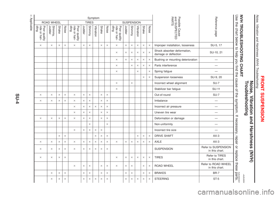
=NJSU0004NVH TROUBLESHOOTING CHARTNJSU0004S01Use the chart below to help you find the cause of the symptom. If necessary, repair or replace these parts.
Reference page
SU-5, 17
SU-10, 21
Ð
Ð
Ð
SU-9, 20
SU-7
SU-11
SU-7
Ð
Ð
Ð
Ð
Ð
Ð
AX-3
AX-3
Refer to SUSPENSION
in this chart.
Refer to TIRES
in this chart.
Refer to ROAD WHEEL
in this chart.
BR-7
ST-5
Possible Cause
and SUSPECTED
PA R T S
Improper installation, looseness
Shock absorber deformation,
damage or deflection
Bushing or mounting deterioration
Parts interference
Spring fatigue
Suspension looseness
Incorrect wheel alignment
Stabilizer bar fatigue
Out-of-round
Imbalance
Incorrect air pressure
Uneven tire wear
Deformation or damage
Non-uniformity
Incorrect tire size
DRIVE SHAFT
AXLE
SUSPENSION
TIRES
ROAD WHEEL
BRAKES
STEERING Symptom
SUSPENSION
Noise´ ´ ´´´´ ´´ ´ ´ ´´
Shake´ ´ ´´ ´ ´´ ´ ´ ´´
Vibration´ ´ ´´´ ´´ ´ ´
Shimmy´´´´ ´ ´ ´ ´´´
Judder´´´ ´ ´ ´´´
Poor quality
ride or han-
dling´ ´ ´´´ ´´ ´ ´ ´
TIRES
Noise´ ´´´´´´ ´´ ´ ´ ´´
Shake´ ´´´´´ ´´´ ´ ´ ´´
Vibration´ ´´´ ´ ´
Shimmy´ ´´´´´´´ ´ ´ ´ ´´
Judder´ ´´´´´ ´ ´ ´ ´ ´´
Poor quality
ride or han-
dling´ ´´´´´ ´ ´ ´ ´
ROAD WHEEL
Noise´ ´´´´´´´´´
Shake´ ´´´´´´´´´
Shimmy,
Judder´´´´´´´´´
Poor quality
ride or han-
dling´´´´´´´
´: Applicable
FRONT SUSPENSION
Noise, Vibration and Harshness (NVH) Troubleshooting
SU-4
Page 2879 of 2898
SFA975B
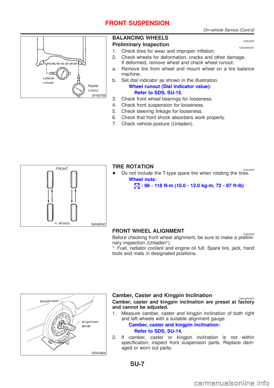
BALANCING WHEELSNJSU0042Preliminary InspectionNJSU0042S011. Check tires for wear and improper inflation.
2. Check wheels for deformation, cracks and other damage.
If deformed, remove wheel and check wheel runout.
a. Remove tire from wheel and mount wheel on a tire balance
machine.
b. Set dial indicator as shown in the illustration.
Wheel runout (Dial indicator value):
Refer to SDS, SU-15.
3. Check front wheel bearings for looseness.
4. Check front suspension for looseness.
5. Check steering linkage for looseness.
6. Check that front shock absorbers work properly.
7. Check vehicle posture (Unladen).
SMA829C
TIRE ROTATIONNJSU0043+Do not include the T-type spare tire when rotating the tires.
Wheel nuts:
: 98 - 118 N´m (10.0 - 12.0 kg-m, 72 - 87 ft-lb)
FRONT WHEEL ALIGNMENTNJSU0045Before checking front wheel alignment, be sure to make a prelimi-
nary inspection (Unladen*).
*: Fuel, radiator coolant and engine oil full. Spare tire, jack, hand
tools and mats in designated positions.
SRA096A
Camber, Caster and Kingpin InclinationNJSU0045S01Camber, caster and kingpin inclination are preset at factory
and cannot be adjusted.
1. Measure camber, caster and kingpin inclination of both right
and left wheels with a suitable alignment gauge.
Camber, caster and kingpin inclination:
Refer to SDS, SU-14.
2. If camber, caster or kingpin inclination is not within
specification, inspect front suspension parts. Replace dam-
aged or worn out parts.
FRONT SUSPENSION
On-vehicle Service (Cont'd)
SU-7
Page 2880 of 2898
AFA050
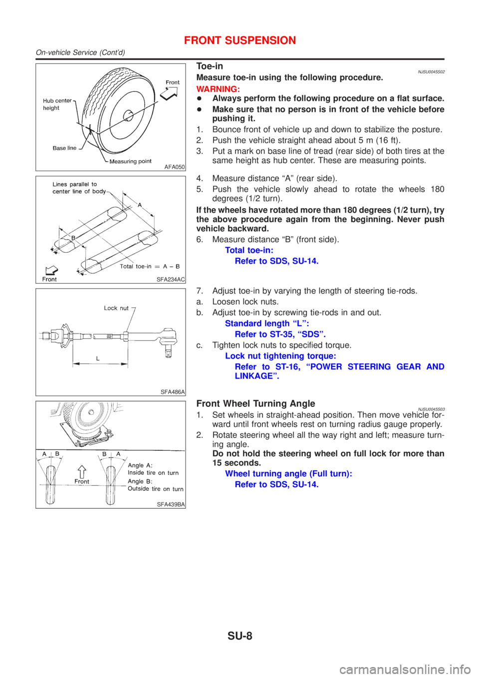
Toe-inNJSU0045S02Measure toe-in using the following procedure.
WARNING:
+Always perform the following procedure on a flat surface.
+Make sure that no person is in front of the vehicle before
pushing it.
1. Bounce front of vehicle up and down to stabilize the posture.
2. Push the vehicle straight ahead about 5 m (16 ft).
3. Put a mark on base line of tread (rear side) of both tires at the
same height as hub center. These are measuring points.
SFA234AC
4. Measure distance ªAº (rear side).
5. Push the vehicle slowly ahead to rotate the wheels 180
degrees (1/2 turn).
If the wheels have rotated more than 180 degrees (1/2 turn), try
the above procedure again from the beginning. Never push
vehicle backward.
6. Measure distance ªBº (front side).
Total toe-in:
Refer to SDS, SU-14.
SFA486A
7. Adjust toe-in by varying the length of steering tie-rods.
a. Loosen lock nuts.
b. Adjust toe-in by screwing tie-rods in and out.
Standard length ªLº:
Refer to ST-35, ªSDSº.
c. Tighten lock nuts to specified torque.
Lock nut tightening torque:
Refer to ST-16, ªPOWER STEERING GEAR AND
LINKAGEº.
SFA439BA
Front Wheel Turning AngleNJSU0045S031. Set wheels in straight-ahead position. Then move vehicle for-
ward until front wheels rest on turning radius gauge properly.
2. Rotate steering wheel all the way right and left; measure turn-
ing angle.
Do not hold the steering wheel on full lock for more than
15 seconds.
Wheel turning angle (Full turn):
Refer to SDS, SU-14.
FRONT SUSPENSION
On-vehicle Service (Cont'd)
SU-8
Page 2881 of 2898
Coil Spring and Shock Absorber
COMPONENTS=NJSU0008
NAX012
1. Strut mount upper plate
2. Strut spacer
3. Strut mount insulator
4. Thrust bearing
5. Upper spring seat
6. Upper rubber seat
7. Bound bumper rubber
8. Coil spring
9. Shock absorber10. Wheel hub and steering knuckle
11. Cotter pin
12. Washer
13. Bush
14. Transverse link
15. Bush
16. Washer
17. Connecting rod
18. Member pin stay19. Suspension member
20. Washer
21. Bush
22. Washer
23. Bush
24. Clamp
25. Stabilizer
26. Washer
FRONT SUSPENSION
Coil Spring and Shock Absorber
SU-9
Page 2886 of 2898
Service Data and Specifications (SDS)
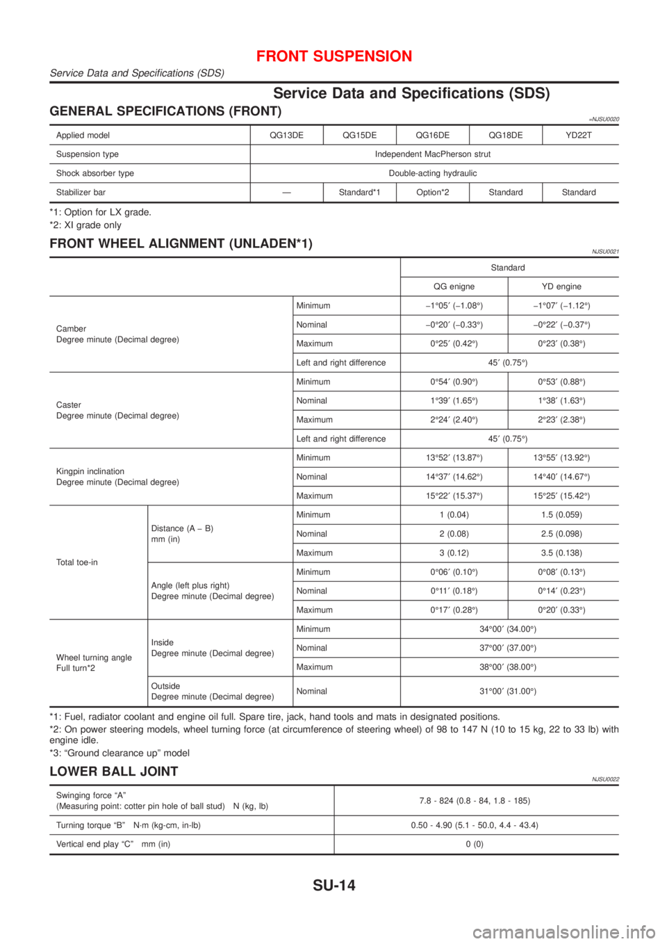
GENERAL SPECIFICATIONS (FRONT)=NJSU0020
Applied model QG13DE QG15DE QG16DE QG18DE YD22T
Suspension type Independent MacPherson strut
Shock absorber type Double-acting hydraulic
Stabilizer bar Ð Standard*1 Option*2 Standard Standard
*1: Option for LX grade.
*2: XI grade only
FRONT WHEEL ALIGNMENT (UNLADEN*1)NJSU0021
Standard
QG enigne YD engine
Camber
Degree minute (Decimal degree)Minimum þ1É05¢(þ1.08É) þ1É07¢(þ1.12É)
Nominal þ0É20¢(þ0.33É) þ0É22¢(þ0.37É)
Maximum 0É25¢(0.42É) 0É23¢(0.38É)
Left and right difference 45¢(0.75É)
Caster
Degree minute (Decimal degree)Minimum 0É54¢(0.90É) 0É53¢(0.88É)
Nominal 1É39¢(1.65É) 1É38¢(1.63É)
Maximum 2É24¢(2.40É) 2É23¢(2.38É)
Left and right difference 45¢(0.75É)
Kingpin inclination
Degree minute (Decimal degree)Minimum 13É52¢(13.87É) 13É55¢(13.92É)
Nominal 14É37¢(14.62É) 14É40¢(14.67É)
Maximum 15É22¢(15.37É) 15É25¢(15.42É)
Total toe-inDistance (A þ B)
mm (in)Minimum 1 (0.04) 1.5 (0.059)
Nominal 2 (0.08) 2.5 (0.098)
Maximum 3 (0.12) 3.5 (0.138)
Angle (left plus right)
Degree minute (Decimal degree)Minimum 0É06¢(0.10É) 0É08¢(0.13É)
Nominal 0É11¢(0.18É) 0É14¢(0.23É)
Maximum 0É17¢(0.28É) 0É20¢(0.33É)
Wheel turning angle
Full turn*2Inside
Degree minute (Decimal degree)Minimum 34É00¢(34.00É)
Nominal 37É00¢(37.00É)
Maximum 38É00¢(38.00É)
Outside
Degree minute (Decimal degree)Nominal 31É00¢(31.00É)
*1: Fuel, radiator coolant and engine oil full. Spare tire, jack, hand tools and mats in designated positions.
*2: On power steering models, wheel turning force (at circumference of steering wheel) of 98 to 147 N (10 to 15 kg, 22 to 33 lb) with
engine idle.
*3: ªGround clearance upº model
LOWER BALL JOINTNJSU0022
Swinging force ªAº
(Measuring point: cotter pin hole of ball stud) N (kg, lb)7.8 - 824 (0.8 - 84, 1.8 - 185)
Turning torque ªBº N´m (kg-cm, in-lb) 0.50 - 4.90 (5.1 - 50.0, 4.4 - 43.4)
Vertical end play ªCº mm (in)0 (0)
FRONT SUSPENSION
Service Data and Specifications (SDS)
SU-14
Page 2891 of 2898
5. Check steering linkage for looseness.
6. Check that front shock absorbers work properly.
7. Check vehicle posture (Unladen).
SFA948A
CamberNJSU0030S02Camber is preset at factory and cannot be adjusted.
Camber:
Refer to SDS, SU-25.
+If the camber is not within specification, inspect and replace
any damaged or worn rear suspension parts.
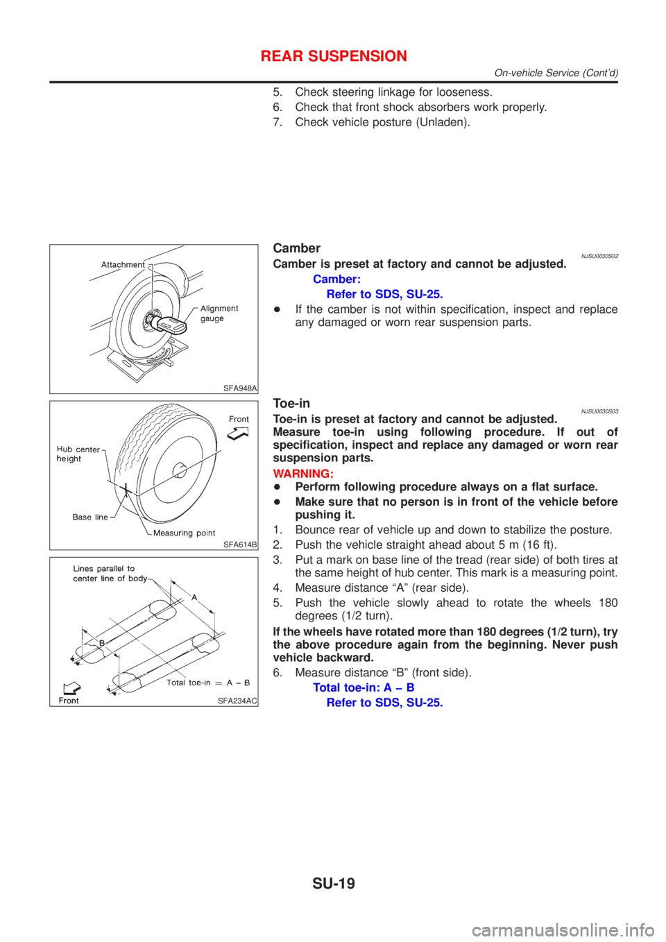
SFA614B
SFA234AC
Toe-inNJSU0030S03Toe-in is preset at factory and cannot be adjusted.
Measure toe-in using following procedure. If out of
specification, inspect and replace any damaged or worn rear
suspension parts.
WARNING:
+Perform following procedure always on a flat surface.
+Make sure that no person is in front of the vehicle before
pushing it.
1. Bounce rear of vehicle up and down to stabilize the posture.
2. Push the vehicle straight ahead about 5 m (16 ft).
3. Put a mark on base line of the tread (rear side) of both tires at
the same height of hub center. This mark is a measuring point.
4. Measure distance ªAº (rear side).
5. Push the vehicle slowly ahead to rotate the wheels 180
degrees (1/2 turn).
If the wheels have rotated more than 180 degrees (1/2 turn), try
the above procedure again from the beginning. Never push
vehicle backward.
6. Measure distance ªBº (front side).
Total toe-in: A þ B
Refer to SDS, SU-25.
REAR SUSPENSION
On-vehicle Service (Cont'd)
SU-19