Page 1191 of 2898
6 CHECK GROUND CIRCUIT
1. Check harness continuity between heated oxygen sensor 2 (rear) harness connector terminal 4 and body ground.
Refer to wiring diagram.
Continuity should exist.
2. Also check harness for short to ground and short to power.
OK or NG
OK©GO TO 7.
NG©Repair open circuit or short to ground or short to power in harness or connectors.
7 CHECK HEATED OXYGEN SENSOR 2 (REAR)
Refer to ªComponent Inspectionº, EC-467.
OK or NG
OK©GO TO 8.
NG©Replace heated oxygen sensor 2 (rear).
8 CHECK INTERMITTENT INCIDENT
Perform ªTROUBLE DIAGNOSIS FOR INTERMITTENT INCIDENTº, EC-177.
©INSPECTION END
SEF662Y
Component InspectionNJEC1239HEATED OXYGEN SENSOR 2 (REAR)NJEC1239S01With CONSULT-II
1) Start engine and drive vehicle at a speed of more than 70 km/h
(43 MPH) for 2 consecutive minutes.
2) Stop vehicle with engine running.
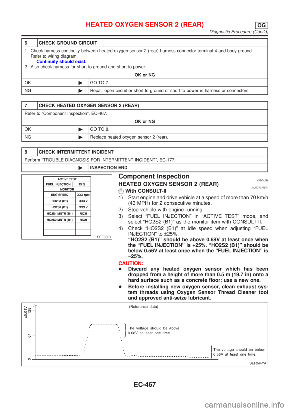
3) Select ªFUEL INJECTIONº in ªACTIVE TESTº mode, and
select ªHO2S2 (B1)º as the monitor item with CONSULT-II.
4) Check ªHO2S2 (B1)º at idle speed when adjusting ªFUEL
INJECTIONº to±25%.
ªHO2S2 (B1)º should be above 0.68V at least once when
the ªFUEL INJECTIONº is +25%. ªHO2S2 (B1)º should be
below 0.56V at least once when the ªFUEL INJECTIONº is
þ25%.
CAUTION:
+Discard any heated oxygen sensor which has been
dropped from a height of more than 0.5 m (19.7 in) onto a
hard surface such as a concrete floor; use a new one.
+Before installing new oxygen sensor, clean exhaust sys-
tem threads using Oxygen Sensor Thread Cleaner tool
and approved anti-seize lubricant.
SEF244YA
HEATED OXYGEN SENSOR 2 (REAR)QG
Diagnostic Procedure (Cont'd)
EC-467
Page 1192 of 2898
SEF032X
Without CONSULT-II
1) Start engine and drive vehicle at a speed of more than 70 km/h
(43 MPH) for 2 consecutive minutes.
2) Stop vehicle with engine running.
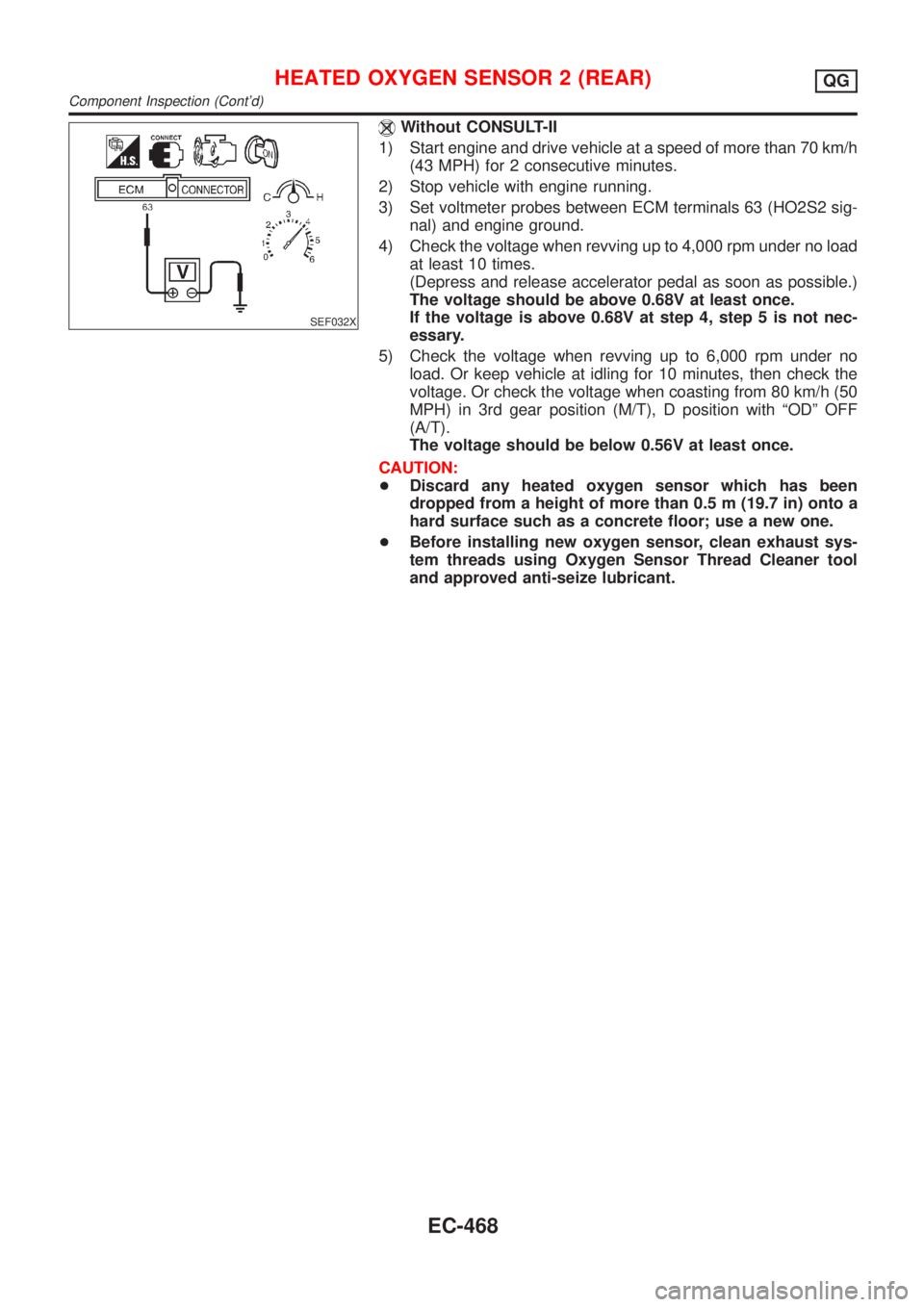
3) Set voltmeter probes between ECM terminals 63 (HO2S2 sig-
nal) and engine ground.
4) Check the voltage when revving up to 4,000 rpm under no load
at least 10 times.
(Depress and release accelerator pedal as soon as possible.)
The voltage should be above 0.68V at least once.
If the voltage is above 0.68V at step 4, step 5 is not nec-
essary.
5) Check the voltage when revving up to 6,000 rpm under no
load. Or keep vehicle at idling for 10 minutes, then check the
voltage. Or check the voltage when coasting from 80 km/h (50
MPH) in 3rd gear position (M/T), D position with ªODº OFF
(A/T).
The voltage should be below 0.56V at least once.
CAUTION:
+Discard any heated oxygen sensor which has been
dropped from a height of more than 0.5 m (19.7 in) onto a
hard surface such as a concrete floor; use a new one.
+Before installing new oxygen sensor, clean exhaust sys-
tem threads using Oxygen Sensor Thread Cleaner tool
and approved anti-seize lubricant.
HEATED OXYGEN SENSOR 2 (REAR)QG
Component Inspection (Cont'd)
EC-468
Page 1196 of 2898
Diagnostic ProcedureNJEC1246
1 CHECK OVERALL FUNCTION
Without CONSULT-II
1. Start engine and drive the vehicle at over 70 km/h (43 MPH) for 2 consecutive minutes.
2. Stop vehicle and keep the engine running.
3. Set the voltmeter probe between ECM terminals 3 [HO2S2 HTR (B1) signal] and ground.
4. Check the voltage under the following conditions.
SEF241Z
OK or NG
OK©INSPECTION END
NG©GO TO 2.
2 CHECK POWER SUPPLY
1. Turn ignition switch ªOFFº.
2. Disconnect heated oxygen sensor 2 (rear) harness connector.
SEF160Z
3. Turn ignition switch ªONº.
4. Check voltage between terminal 2 and ground.
SEF218W
OK or NG
OK©GO TO 4.
NG©GO TO 3.
HEATED OXYGEN SENSOR 2 HEATER (REAR)QG
Diagnostic Procedure
EC-472
Page 1242 of 2898
8 CHECK VACUUM HOSES AND TUBES
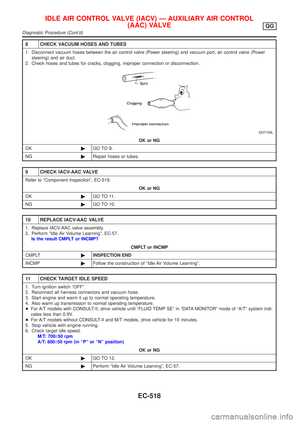
1. Disconnect vacuum hoses between the air control valve (Power steering) and vacuum port, air control valve (Power
steering) and air duct.
2. Check hoses and tubes for cracks, clogging, improper connection or disconnection.
SEF109L
OK or NG
OK©GO TO 9.
NG©Repair hoses or tubes.
9 CHECK IACV-AAC VALVE
Refer to ªComponent Inspectionº, EC-519.
OK or NG
OK©GO TO 11.
NG©GO TO 10.
10 REPLACE IACV-AAC VALVE
1. Replace IACV-AAC valve assembly.
2. Perform ªIdle Air Volume Learningº, EC-57.
Is the result CMPLT or INCMP?
CMPLT or INCMP
CMPLT©INSPECTION END
INCMP©Follow the construction of ªIdle Air Volume Learningº.
11 CHECK TARGET IDLE SPEED
1. Turn ignition switch ªOFFº.
2. Reconnect all harness connectors and vacuum hose.
3. Start engine and warm it up to normal operating temperature.
4. Also warm up transmission to normal operating temperature.
+For A/T models with CONSULT-II, drive vehicle until ªFLUID TEMP SEº in ªDATA MONITORº mode of ªA/Tº system indi-
cates less than 0.9V.
+For A/T models without CONSULT-II and M/T models, drive vehicle for 10 minutes.
5. Stop vehicle with engine running.
6. Check target idle speed.
M/T: 700±50 rpm
A/T: 800±50 rpm (in ªPº or ªNº position)
OK or NG
OK©GO TO 12.
NG©Perform ªIdle Air Volume Learningº, EC-57.
IDLE AIR CONTROL VALVE (IACV) Ð AUXILIARY AIR CONTROL
(AAC) VALVE
QG
Diagnostic Procedure (Cont'd)
EC-518
Page 1285 of 2898
System DescriptionNJEC0444
Sensor Input Signal to ECMECM func-
tionActuator
Crankshaft position sensor (POS) Engine speed
Fuel pump
controlFuel pump relay Camshaft position sensor (PHASE) Engine speed and cylinder number
Ignition switch Ignition signal and start signal
The ECM activates the fuel pump for several seconds after the ignition switch is turned on to improve engine
startability. If the ECM receives a 180É signal from the camshaft position sensor, it knows that the engine is
rotating, and causes the pump to perform. If the 180É signal is not received when the ignition switch is on, the
engine stalls. The ECM stops pump operation and prevents battery discharging, thereby improving safety. The
ECM does not directly drive the fuel pump. It controls the ON/OFF fuel pump relay, which in turn controls the
fuel pump.
Condition Fuel pump operation
Ignition switch is turned to ON. Operates for 1 second
Engine running and cranking Operates
When engine is stopped (Signal is not sent from crankshaft position sensor
and camshaft position sensor.)Stops in 1.5 seconds
Except as shown aboveStops
SEF605X
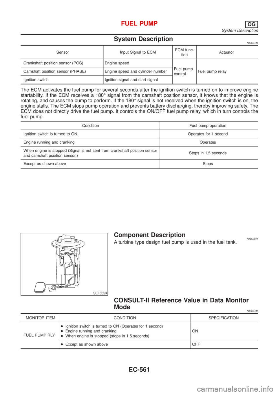
Component DescriptionNJEC0501A turbine type design fuel pump is used in the fuel tank.
CONSULT-II Reference Value in Data Monitor
Mode
NJEC0445
MONITOR ITEM CONDITION SPECIFICATION
FUEL PUMP RLY+Ignition switch is turned to ON (Operates for 1 second)
+Engine running and cranking
+When engine is stopped (stops in 1.5 seconds)ON
+Except as shown above OFF
FUEL PUMPQG
System Description
EC-561
Page 1299 of 2898
Diagnostic ProcedureNJEC0590
1 CHECK REFRIGERANT PRESSURE SENSOR OVERALL FUNCTION
1. Start engine and warm it up to normal operating temperature.
2. Turn A/C switch and blower switch ªONº.
3. Check voltage between ECM terminal 74 and ground with CONSULT-II or tester.
SEF952XA
OK or NG
OK©INSPECTION END
NG©GO TO 2.
2 CHECK REFRIGERANT PRESSURE SENSOR POWER SUPPLY CIRCUIT
1. Turn A/C switch and blower switch ªOFFº.
2. Stop engine.
3. Disconnect refrigerant pressure sensor harness connector.
JEF147Y
4. Turn ignition switch ªONº.
5. Check voltage between refrigerant pressure sensor terminal 3 and ground with CONSULT-II or tester.
SEF953X
OK or NG
OK©GO TO 4.
NG©GO TO 3.
REFRIGERANT PRESSURE SENSORQG
Diagnostic Procedure
EC-575
Page 1349 of 2898
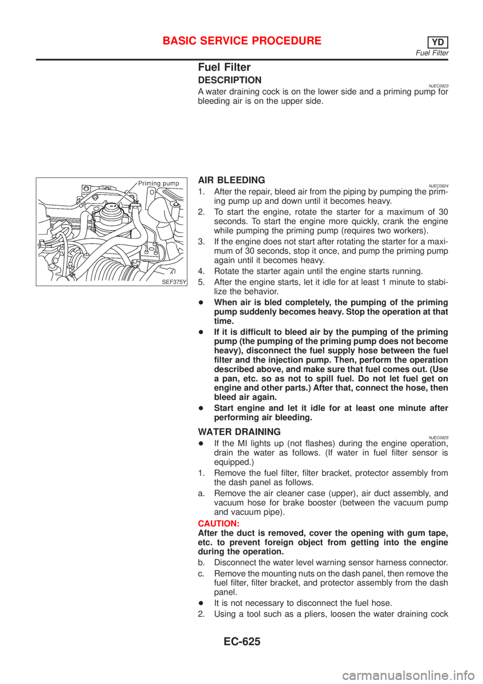
Fuel Filter
DESCRIPTIONNJEC0623A water draining cock is on the lower side and a priming pump for
bleeding air is on the upper side.
SEF375Y
AIR BLEEDINGNJEC06241. After the repair, bleed air from the piping by pumping the prim-
ing pump up and down until it becomes heavy.
2. To start the engine, rotate the starter for a maximum of 30
seconds. To start the engine more quickly, crank the engine
while pumping the priming pump (requires two workers).
3. If the engine does not start after rotating the starter for a maxi-
mum of 30 seconds, stop it once, and pump the priming pump
again until it becomes heavy.
4. Rotate the starter again until the engine starts running.
5. After the engine starts, let it idle for at least 1 minute to stabi-
lize the behavior.
+When air is bled completely, the pumping of the priming
pump suddenly becomes heavy. Stop the operation at that
time.
+If it is difficult to bleed air by the pumping of the priming
pump (the pumping of the priming pump does not become
heavy), disconnect the fuel supply hose between the fuel
filter and the injection pump. Then, perform the operation
described above, and make sure that fuel comes out. (Use
a pan, etc. so as not to spill fuel. Do not let fuel get on
engine and other parts.) After that, connect the hose, then
bleed air again.
+Start engine and let it idle for at least one minute after
performing air bleeding.
WATER DRAININGNJEC0625+If the MI lights up (not flashes) during the engine operation,
drain the water as follows. (If water in fuel filter sensor is
equipped.)
1. Remove the fuel filter, filter bracket, protector assembly from
the dash panel as follows.
a. Remove the air cleaner case (upper), air duct assembly, and
vacuum hose for brake booster (between the vacuum pump
and vacuum pipe).
CAUTION:
After the duct is removed, cover the opening with gum tape,
etc. to prevent foreign object from getting into the engine
during the operation.
b. Disconnect the water level warning sensor harness connector.
c. Remove the mounting nuts on the dash panel, then remove the
fuel filter, filter bracket, and protector assembly from the dash
panel.
+It is not necessary to disconnect the fuel hose.
2. Using a tool such as a pliers, loosen the water draining cock
BASIC SERVICE PROCEDUREYD
Fuel Filter
EC-625
Page 1352 of 2898
+Erasing the emission-related diagnostic information using CONSULT-II is easier and quicker than
switching the diagnostic test mode using the data link connector.
Malfunction Indicator (MI)
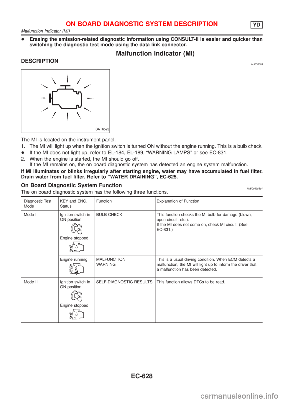
DESCRIPTIONNJEC0628
SAT652J
The MI is located on the instrument panel.
1. The MI will light up when the ignition switch is turned ON without the engine running. This is a bulb check.
+If the MI does not light up, refer to EL-184, EL-189, ªWARNING LAMPSº or see EC-831.
2. When the engine is started, the MI should go off.
If the MI remains on, the on board diagnostic system has detected an engine system malfunction.
If MI illuminates or blinks irregularly after starting engine, water may have accumulated in fuel filter.
Drain water from fuel filter. Refer to ªWATER DRAININGº, EC-625.
On Board Diagnostic System FunctionNJEC0628S01The on board diagnostic system has the following three functions.
Diagnostic Test
ModeKEY and ENG.
StatusFunction Explanation of Function
Mode I Ignition switch in
ON position
Engine stopped
BULB CHECK This function checks the MI bulb for damage (blown,
open circuit, etc.).
If the MI does not come on, check MI circuit. (See
EC-831.)
Engine running
MALFUNCTION
WARNINGThis is a usual driving condition. When ECM detects a
malfunction, the MI will light up to inform the driver that
a malfunction has been detected.
Mode II Ignition switch in
ON position
Engine stopped
SELF-DIAGNOSTIC RESULTS This function allows DTCs to be read.
ON BOARD DIAGNOSTIC SYSTEM DESCRIPTIONYD
Malfunction Indicator (MI)
EC-628