2001 NISSAN ALMERA stop start
[x] Cancel search: stop startPage 2537 of 2898
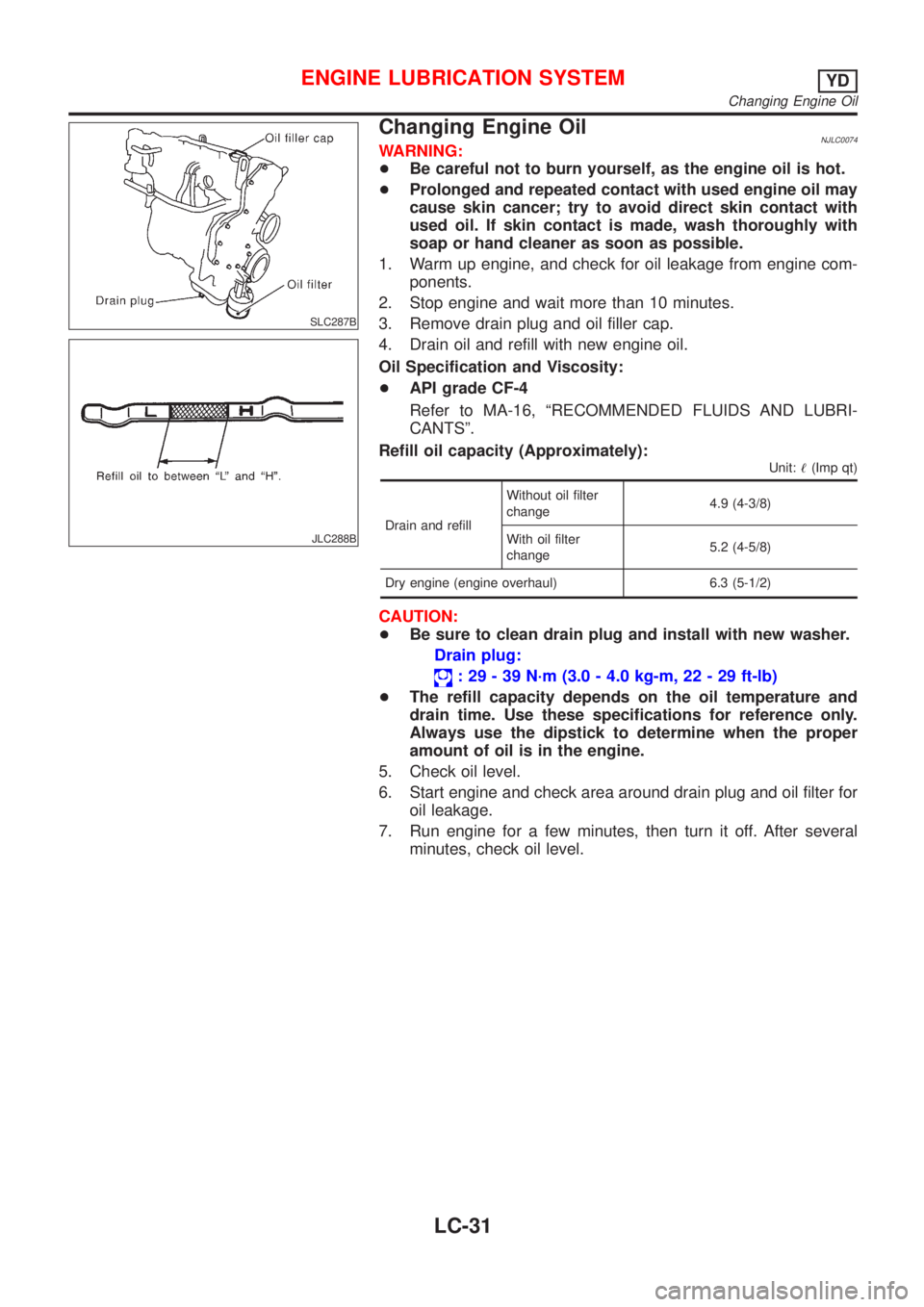
SLC287B
JLC288B
Changing Engine OilNJLC0074WARNING:
+Be careful not to burn yourself, as the engine oil is hot.
+Prolonged and repeated contact with used engine oil may
cause skin cancer; try to avoid direct skin contact with
used oil. If skin contact is made, wash thoroughly with
soap or hand cleaner as soon as possible.
1. Warm up engine, and check for oil leakage from engine com-
ponents.
2. Stop engine and wait more than 10 minutes.
3. Remove drain plug and oil filler cap.
4. Drain oil and refill with new engine oil.
Oil Specification and Viscosity:
+API grade CF-4
Refer to MA-16, ªRECOMMENDED FLUIDS AND LUBRI-
CANTSº.
Refill oil capacity (Approximately):
Unit:!(Imp qt)
Drain and refillWithout oil filter
change4.9 (4-3/8)
With oil filter
change5.2 (4-5/8)
Dry engine (engine overhaul) 6.3 (5-1/2)
CAUTION:
+Be sure to clean drain plug and install with new washer.
Drain plug:
: 29 - 39 N´m (3.0 - 4.0 kg-m, 22 - 29 ft-lb)
+The refill capacity depends on the oil temperature and
drain time. Use these specifications for reference only.
Always use the dipstick to determine when the proper
amount of oil is in the engine.
5. Check oil level.
6. Start engine and check area around drain plug and oil filter for
oil leakage.
7. Run engine for a few minutes, then turn it off. After several
minutes, check oil level.
ENGINE LUBRICATION SYSTEMYD
Changing Engine Oil
LC-31
Page 2551 of 2898
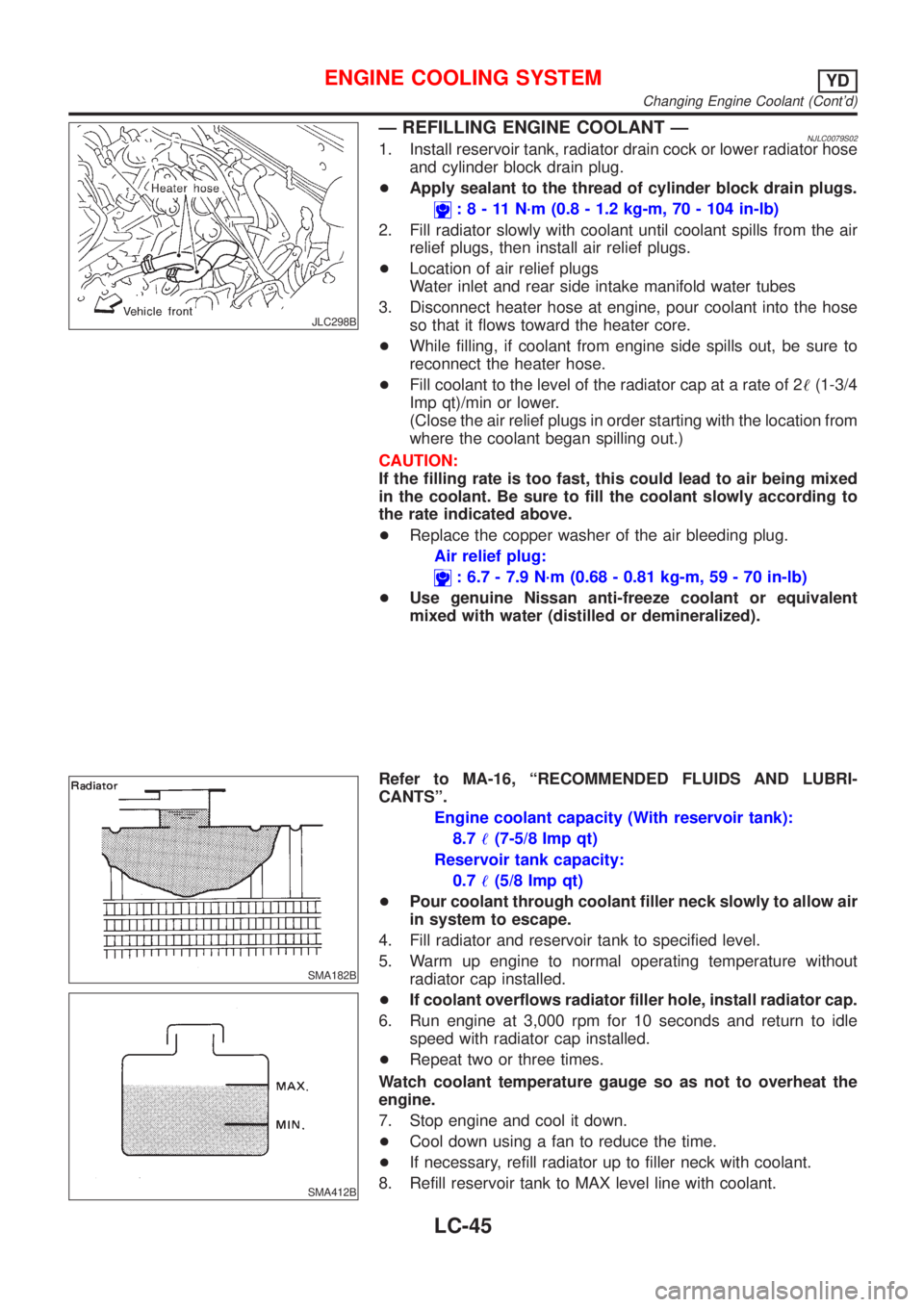
JLC298B
Ð REFILLING ENGINE COOLANT ÐNJLC0079S021. Install reservoir tank, radiator drain cock or lower radiator hose
and cylinder block drain plug.
+Apply sealant to the thread of cylinder block drain plugs.
:8-11N´m(0.8 - 1.2 kg-m, 70 - 104 in-lb)
2. Fill radiator slowly with coolant until coolant spills from the air
relief plugs, then install air relief plugs.
+Location of air relief plugs
Water inlet and rear side intake manifold water tubes
3. Disconnect heater hose at engine, pour coolant into the hose
so that it flows toward the heater core.
+While filling, if coolant from engine side spills out, be sure to
reconnect the heater hose.
+Fill coolant to the level of the radiator cap at a rate of 2!(1-3/4
Imp qt)/min or lower.
(Close the air relief plugs in order starting with the location from
where the coolant began spilling out.)
CAUTION:
If the filling rate is too fast, this could lead to air being mixed
in the coolant. Be sure to fill the coolant slowly according to
the rate indicated above.
+Replace the copper washer of the air bleeding plug.
Air relief plug:
: 6.7 - 7.9 N´m (0.68 - 0.81 kg-m, 59 - 70 in-lb)
+Use genuine Nissan anti-freeze coolant or equivalent
mixed with water (distilled or demineralized).
SMA182B
SMA412B
Refer to MA-16, ªRECOMMENDED FLUIDS AND LUBRI-
CANTSº.
Engine coolant capacity (With reservoir tank):
8.7!(7-5/8 Imp qt)
Reservoir tank capacity:
0.7!(5/8 Imp qt)
+Pour coolant through coolant filler neck slowly to allow air
in system to escape.
4. Fill radiator and reservoir tank to specified level.
5. Warm up engine to normal operating temperature without
radiator cap installed.
+If coolant overflows radiator filler hole, install radiator cap.
6. Run engine at 3,000 rpm for 10 seconds and return to idle
speed with radiator cap installed.
+Repeat two or three times.
Watch coolant temperature gauge so as not to overheat the
engine.
7. Stop engine and cool it down.
+Cool down using a fan to reduce the time.
+If necessary, refill radiator up to filler neck with coolant.
8. Refill reservoir tank to MAX level line with coolant.
ENGINE COOLING SYSTEMYD
Changing Engine Coolant (Cont'd)
LC-45
Page 2805 of 2898
![NISSAN ALMERA 2001 Service Manual Fig. 2 INITIAL CHARGING CURRENT SETTING (Slow charge)
CON-
VERTED
SPECIFIC
GRAVITYBATTERY TYPE
28B19R(L)
34B19R(L)
46B24R(L)
55B24R(L)
50D23R(L)
55D23R(L)
025 [YUASA type code]
027 [YUASA type code]
6 NISSAN ALMERA 2001 Service Manual Fig. 2 INITIAL CHARGING CURRENT SETTING (Slow charge)
CON-
VERTED
SPECIFIC
GRAVITYBATTERY TYPE
28B19R(L)
34B19R(L)
46B24R(L)
55B24R(L)
50D23R(L)
55D23R(L)
025 [YUASA type code]
027 [YUASA type code]
6](/manual-img/5/57348/w960_57348-2804.png)
Fig. 2 INITIAL CHARGING CURRENT SETTING (Slow charge)
CON-
VERTED
SPECIFIC
GRAVITYBATTERY TYPE
28B19R(L)
34B19R(L)
46B24R(L)
55B24R(L)
50D23R(L)
55D23R(L)
025 [YUASA type code]
027 [YUASA type code]
65D26R(L)
80D26R(L)
063 [YUASA type code]
067 [YUASA type code]
096 [YUASA type code]
75D31R(L)
95D31R(L)
115D31R(L)
110D26R(L)
95E41R(L)
065 [YUASA type code]
075 [YUASA type code]
096L [YUASA type code]
010S [YUASA type code]
130E41R(L)
Below 1.100 4.0 (A) 5.0 (A) 7.0 (A) 8.0 (A)8.5
(A)9.0
(A)10.0 (A) 11.0 (A)14.0
(A)
+Check battery type and determine the specified current using the table shown above.
+After starting charging, adjustment of charging current is not necessary.
Fig. 3 ADDITIONAL CHARGE (Slow charge)
SEL757W
*: SC-7
CAUTION:
+Set charging current to value specified in Fig. 2. If charger is not capable of producing specified
current value, set its charging current as close to that value as possible.
+Keep battery away from open flame while it is being charged.
+When connecting charger, connect leads first, then turn on charger. Do not turn on charger first,
as this may cause a spark.
+If battery temperature rises above 60ÉC (140ÉF), stop charging. Always charge battery when its
temperature is below 60ÉC (140ÉF).
BATTERY
Battery Test and Charging Chart (Cont'd)
SC-9
Page 2808 of 2898
![NISSAN ALMERA 2001 Service Manual Fig. 6 INITIAL CHARGING CURRENT SETTING AND CHARGING TIME (Quick charge)
BATTERY
TYPE
28B19R(L)
34B19R(L)
46B24R(L)
55B24R(L)
50D23R(L)
55D23R(L)
65D26R(L)
80D26R(L)
025 [YUASA type code]
027 [YUASA t NISSAN ALMERA 2001 Service Manual Fig. 6 INITIAL CHARGING CURRENT SETTING AND CHARGING TIME (Quick charge)
BATTERY
TYPE
28B19R(L)
34B19R(L)
46B24R(L)
55B24R(L)
50D23R(L)
55D23R(L)
65D26R(L)
80D26R(L)
025 [YUASA type code]
027 [YUASA t](/manual-img/5/57348/w960_57348-2807.png)
Fig. 6 INITIAL CHARGING CURRENT SETTING AND CHARGING TIME (Quick charge)
BATTERY
TYPE
28B19R(L)
34B19R(L)
46B24R(L)
55B24R(L)
50D23R(L)
55D23R(L)
65D26R(L)
80D26R(L)
025 [YUASA type code]
027 [YUASA type code]
063 [YUASA type code]
067 [YUASA type code]
096 [YUASA type code]
065 [YUASA type code]
075 [YUASA type code]
096L [YUASA type code]
010S [YUASA type code]
75D31R(L)
95D31R(L)
115D31R(L)
110D26R(L)
95E41R(L)
130E41R(L)
CURRENT
[A]10 (A) 15 (A) 20 (A) 25 (A) 30 (A)40
(A)
CONVERTED SPECIFIC GRAVITY
1.100 -
1.1302.5 hours
1.130 -
1.1602.0 hours
1.160 -
1.1901.5 hours
1.190 -
1.2201.0 hours
Above
1.2200.75 hours (45 min.)
+Check battery type and determine the specified current using the table shown above.
+After starting charging, adjustment of charging current is not necessary.
CAUTION:
+Do not use quick charge method on a battery whose specific gravity is less than 1.100.
+Set initial charging current to value specified in Fig. 6. If charger is not capable of producing
specified current value, set its charging current as close to that value as possible.
+Keep battery away from open flame while it is being charged.
+When connecting charger, connect leads first, then turn on charger. Do not turn on charger first,
as this may cause a spark.
+Be careful of a rise in battery temperature because a large current flow is required during quick-
charge operation.
If battery temperature rises above 60ÉC (140ÉF), stop charging. Always charge battery when its
temperature is below 60ÉC (140ÉF).
+Do not exceed the charging time specified in Fig. 6, because charging battery over the charging
time can cause deterioration of the battery.
BATTERY
Battery Test and Charging Chart (Cont'd)
SC-12
Page 2820 of 2898
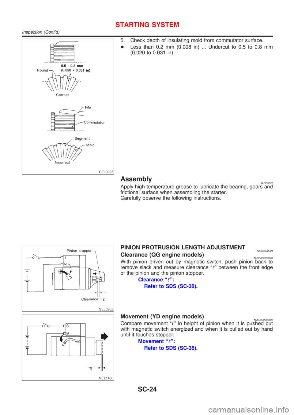
SEL022Z
5. Check depth of insulating mold from commutator surface.
+Less than 0.2 mm (0.008 in) ... Undercut to 0.5 to 0.8 mm
(0.020 to 0.031 in)
AssemblyNJSC0020Apply high-temperature grease to lubricate the bearing, gears and
frictional surface when assembling the starter.
Carefully observe the following instructions.
SEL026Z
PINION PROTRUSION LENGTH ADJUSTMENTNJSC0020S01Clearance (QG engine models)NJSC0020S0101With pinion driven out by magnetic switch, push pinion back to
remove slack and measure clearance ª!º between the front edge
of the pinion and the pinion stopper.
Clearance ª!º:
Refer to SDS (SC-38).
MEL140L
Movement (YD engine models)NJSC0020S0102Compare movement ª!º in height of pinion when it is pushed out
with magnetic switch energized and when it is pulled out by hand
until it touches stopper.
Movement ª!º:
Refer to SDS (SC-38).
STARTING SYSTEM
Inspection (Cont'd)
SC-24
Page 2834 of 2898
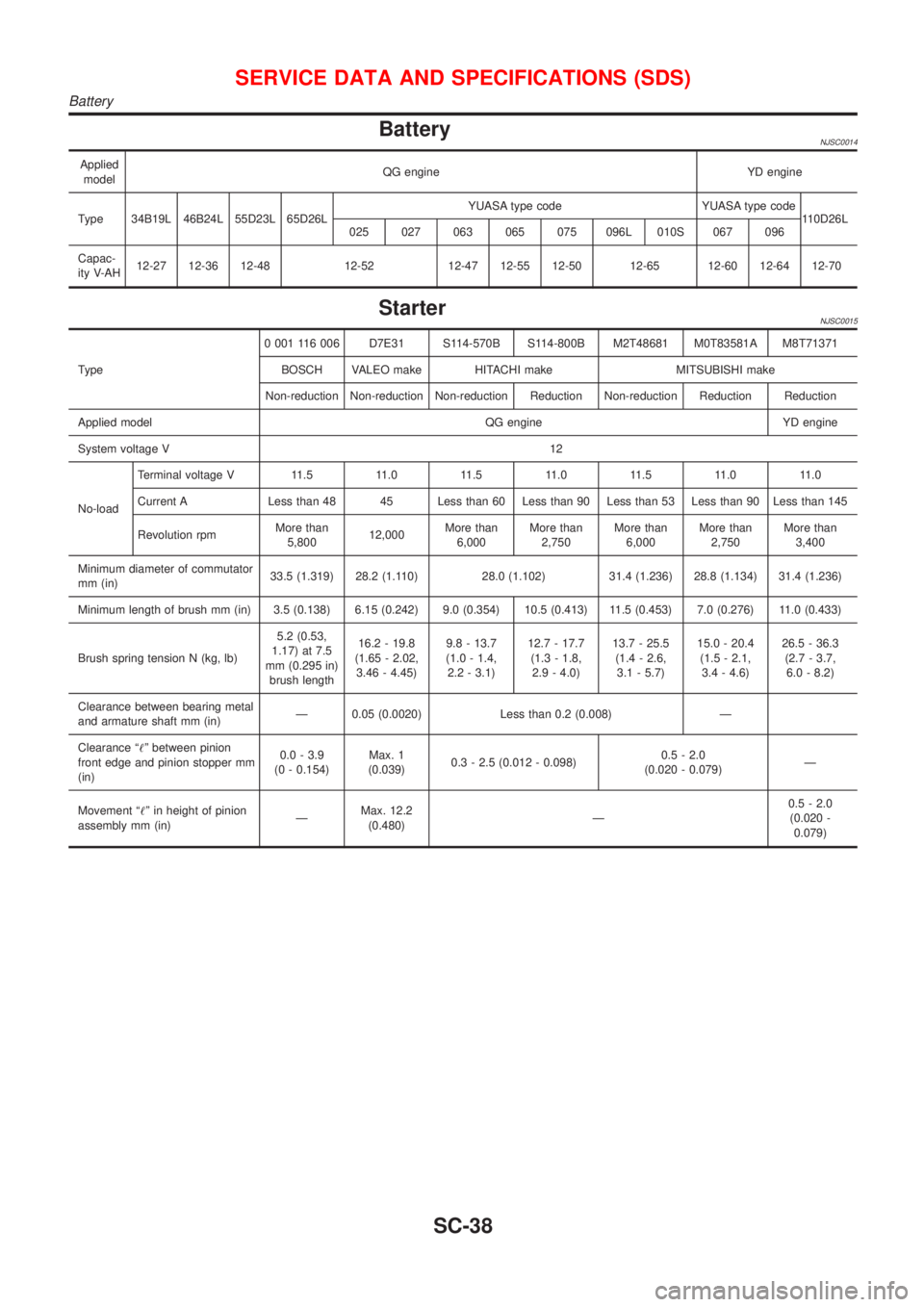
BatteryNJSC0014
Applied
modelQG engine YD engine
Type 34B19L 46B24L 55D23L 65D26LYUASA type code YUASA type code
110D26L
025 027 063 065 075 096L 010S 067 096
Capac-
ity V-AH12-27 12-36 12-48 12-52 12-47 12-55 12-50 12-65 12-60 12-64 12-70
StarterNJSC0015
Type0 001 116 006 D7E31 S114-570B S114-800B M2T48681 M0T83581A M8T71371
BOSCH VALEO make HITACHI make MITSUBISHI make
Non-reduction Non-reduction Non-reduction Reduction Non-reduction Reduction Reduction
Applied model QG engine YD engine
System voltage V12
No-loadTerminal voltage V 11.5 11.0 11.5 11.0 11.5 11.0 11.0
Current A Less than 48 45 Less than 60 Less than 90 Less than 53 Less than 90 Less than 145
Revolution rpmMore than
5,80012,000More than
6,000More than
2,750More than
6,000More than
2,750More than
3,400
Minimum diameter of commutator
mm (in)33.5 (1.319) 28.2 (1.110) 28.0 (1.102) 31.4 (1.236) 28.8 (1.134) 31.4 (1.236)
Minimum length of brush mm (in) 3.5 (0.138) 6.15 (0.242) 9.0 (0.354) 10.5 (0.413) 11.5 (0.453) 7.0 (0.276) 11.0 (0.433)
Brush spring tension N (kg, lb)5.2 (0.53,
1.17) at 7.5
mm (0.295 in)
brush length16.2 - 19.8
(1.65 - 2.02,
3.46 - 4.45)9.8 - 13.7
(1.0 - 1.4,
2.2 - 3.1)12.7 - 17.7
(1.3 - 1.8,
2.9 - 4.0)13.7 - 25.5
(1.4 - 2.6,
3.1 - 5.7)15.0 - 20.4
(1.5 - 2.1,
3.4 - 4.6)26.5 - 36.3
(2.7 - 3.7,
6.0 - 8.2)
Clearance between bearing metal
and armature shaft mm (in)Ð 0.05 (0.0020) Less than 0.2 (0.008) Ð
Clearance ª!º between pinion
front edge and pinion stopper mm
(in)0.0 - 3.9
(0 - 0.154)Max. 1
(0.039)0.3 - 2.5 (0.012 - 0.098)0.5 - 2.0
(0.020 - 0.079)Ð
Movement ª!º in height of pinion
assembly mm (in)ÐMax. 12.2
(0.480)Ð0.5 - 2.0
(0.020 -
0.079)
SERVICE DATA AND SPECIFICATIONS (SDS)
Battery
SC-38
Page 2844 of 2898
Bleeding Hydraulic SystemNJST00141. Raise front end of vehicle until wheels are clear of the ground.
2. Add fluid into oil tank to specified level. Then quickly turn steer-
ing wheel fully to right and left and lightly touch steering stop-
pers.
Repeat steering wheel operation until fluid level no longer
decreases.
3. Start engine.
Repeat step 2. above.
+Incomplete air bleeding will cause the following to occur. When
this happens, bleed air again.
a) Air bubbles in reservoir tank
b) Clicking noise in oil pump
c) Excessive buzzing in oil pump
Fluid noise may occur in the valve or oil pump. This is common
when the vehicle is stationary or while turning the steering wheel
slowly. This does not affect the performance or durability of the
system.
SST491B
SST090B
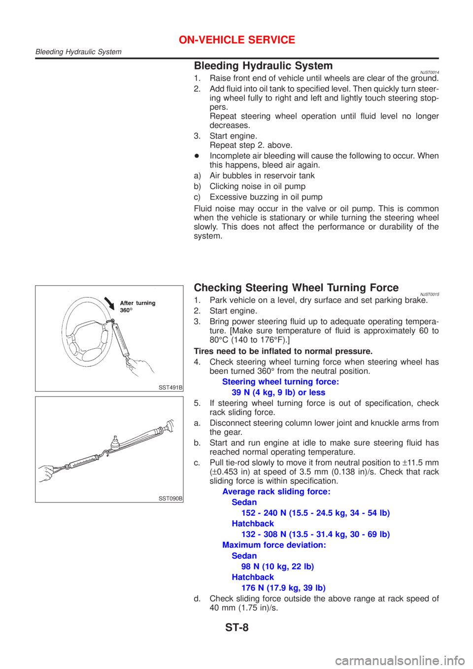
Checking Steering Wheel Turning ForceNJST00151. Park vehicle on a level, dry surface and set parking brake.
2. Start engine.
3. Bring power steering fluid up to adequate operating tempera-
ture. [Make sure temperature of fluid is approximately 60 to
80ÉC (140 to 176ÉF).]
Tires need to be inflated to normal pressure.
4. Check steering wheel turning force when steering wheel has
been turned 360É from the neutral position.
Steering wheel turning force:
39 N (4 kg, 9 lb) or less
5. If steering wheel turning force is out of specification, check
rack sliding force.
a. Disconnect steering column lower joint and knuckle arms from
the gear.
b. Start and run engine at idle to make sure steering fluid has
reached normal operating temperature.
c. Pull tie-rod slowly to move it from neutral position to±11.5 mm
(±0.453 in) at speed of 3.5 mm (0.138 in)/s. Check that rack
sliding force is within specification.
Average rack sliding force:
Sedan
152 - 240 N (15.5 - 24.5 kg, 34 - 54 lb)
Hatchback
132 - 308 N (13.5 - 31.4 kg, 30 - 69 lb)
Maximum force deviation:
Sedan
98 N (10 kg, 22 lb)
Hatchback
176 N (17.9 kg, 39 lb)
d. Check sliding force outside the above range at rack speed of
40 mm (1.75 in)/s.
ON-VEHICLE SERVICE
Bleeding Hydraulic System
ST-8