2001 NISSAN ALMERA stop start
[x] Cancel search: stop startPage 2260 of 2898
SEM934C
JEM157G
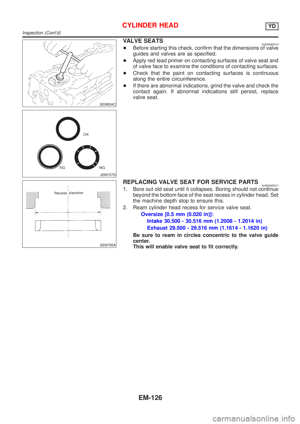
VALVE SEATSNJEM0065S10+Before starting this check, confirm that the dimensions of valve
guides and valves are as specified.
+Apply red lead primer on contacting surfaces of valve seat and
of valve face to examine the conditions of contacting surfaces.
+Check that the paint on contacting surfaces is continuous
along the entire circumference.
+If there are abnormal indications, grind the valve and check the
contact again. If abnormal indications still persist, replace
valve seat.
SEM795A
REPLACING VALVE SEAT FOR SERVICE PARTSNJEM0065S111. Bore out old seat until it collapses. Boring should not continue
beyond the bottom face of the seat recess in cylinder head. Set
the machine depth stop to ensure this.
2. Ream cylinder head recess for service valve seat.
Oversize [0.5 mm (0.020 in)]:
Intake 30.500 - 30.516 mm (1.2008 - 1.2014 in)
Exhaust 29.500 - 29.516 mm (1.1614 - 1.1620 in)
Be sure to ream in circles concentric to the valve guide
center.
This will enable valve seat to fit correctly.
CYLINDER HEADYD
Inspection (Cont'd)
EM-126
Page 2325 of 2898
JFE624A
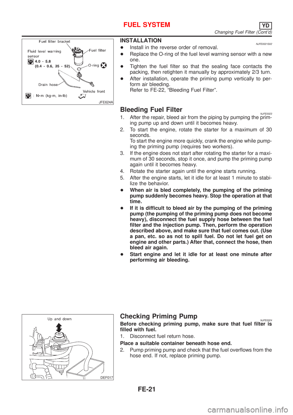
INSTALLATIONNJFE0021S02+Install in the reverse order of removal.
+Replace the O-ring of the fuel level warning sensor with a new
one.
+Tighten the fuel filter so that the sealing face contacts the
packing, then retighten it manually by approximately 2/3 turn.
+After installation, operate the priming pump vertically to per-
form air bleeding.
Refer to FE-22, ªBleeding Fuel Filterº.
Bleeding Fuel FilterNJFE00231. After the repair, bleed air from the piping by pumping the prim-
ing pump up and down until it becomes heavy.
2. To start the engine, rotate the starter for a maximum of 30
seconds.
To start the engine more quickly, crank the engine while pump-
ing the priming pump (requires two workers).
3. If the engine does not start after rotating the starter for a maxi-
mum of 30 seconds, stop it once, and pump the priming pump
again until it becomes heavy.
4. Rotate the starter again until the engine starts running.
5. After the engine starts, let it idle for at least 1 minute to stabi-
lize the behavior.
+When air is bled completely, the pumping of the priming
pump suddenly becomes heavy. Stop the operation at that
time.
+If it is difficult to bleed air by the pumping of the priming
pump (the pumping of the priming pump does not become
heavy), disconnect the fuel supply hose between the fuel
filter and the injection pump. Then, perform the operation
described above, and make sure that fuel comes out. (Use
a pan, etc. so as not to spill fuel. Do not let fuel get on
engine and other parts.) After that, connect the hose, then
bleed air again.
+Start engine and let it idle for at least one minute after
performing air bleeding.
DEF017
Checking Priming PumpNJFE0024Before checking priming pump, make sure that fuel filter is
filled with fuel.
1. Disconnect fuel return hose.
Place a suitable container beneath hose end.
2. Pump priming pump and check that the fuel overflows from the
hose end. If not, replace priming pump.
FUEL SYSTEMYD
Changing Fuel Filter (Cont'd)
FE-21
Page 2379 of 2898
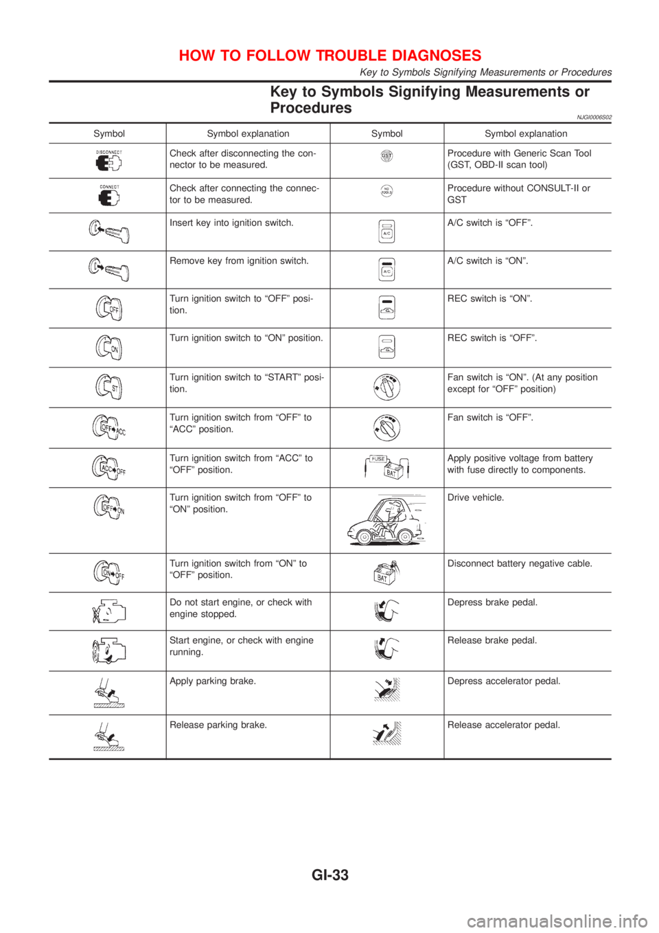
Key to Symbols Signifying Measurements or
Procedures
NJGI0006S02
Symbol Symbol explanation Symbol Symbol explanation
Check after disconnecting the con-
nector to be measured.Procedure with Generic Scan Tool
(GST, OBD-II scan tool)
Check after connecting the connec-
tor to be measured.Procedure without CONSULT-II or
GST
Insert key into ignition switch.A/C switch is ªOFFº.
Remove key from ignition switch.A/C switch is ªONº.
Turn ignition switch to ªOFFº posi-
tion.REC switch is ªONº.
Turn ignition switch to ªONº position.REC switch is ªOFFº.
Turn ignition switch to ªSTARTº posi-
tion.Fan switch is ªONº. (At any position
except for ªOFFº position)
Turn ignition switch from ªOFFº to
ªACCº position.Fan switch is ªOFFº.
Turn ignition switch from ªACCº to
ªOFFº position.Apply positive voltage from battery
with fuse directly to components.
Turn ignition switch from ªOFFº to
ªONº position.Drive vehicle.
Turn ignition switch from ªONº to
ªOFFº position.Disconnect battery negative cable.
Do not start engine, or check with
engine stopped.Depress brake pedal.
Start engine, or check with engine
running.Release brake pedal.
Apply parking brake.Depress accelerator pedal.
Release parking brake.Release accelerator pedal.
HOW TO FOLLOW TROUBLE DIAGNOSES
Key to Symbols Signifying Measurements or Procedures
GI-33
Page 2475 of 2898
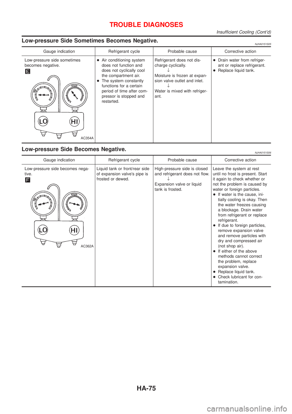
Low-pressure Side Sometimes Becomes Negative.NJHA0151S05
Gauge indication Refrigerant cycle Probable cause Corrective action
Low-pressure side sometimes
becomes negative.
AC354A
+Air conditioning system
does not function and
does not cyclically cool
the compartment air.
+The system constantly
functions for a certain
period of time after com-
pressor is stopped and
restarted.Refrigerant does not dis-
charge cyclically.
¯
Moisture is frozen at expan-
sion valve outlet and inlet.
¯
Water is mixed with refriger-
ant.+Drain water from refriger-
ant or replace refrigerant.
+Replace liquid tank.
Low-pressure Side Becomes Negative.NJHA0151S06
Gauge indication Refrigerant cycle Probable cause Corrective action
Low-pressure side becomes nega-
tive.
AC362A
Liquid tank or front/rear side
of expansion valve's pipe is
frosted or dewed.High-pressure side is closed
and refrigerant does not flow.
¯
Expansion valve or liquid
tank is frosted.Leave the system at rest
until no frost is present. Start
it again to check whether or
not the problem is caused by
water or foreign particles.
+If water is the cause, ini-
tially cooling is okay. Then
the water freezes causing
a blockage. Drain water
from refrigerant or replace
refrigerant.
+If due to foreign particles,
remove expansion valve
and remove particles with
dry and compressed air
(not shop air).
+If either of the above
methods cannot correct
the problem, replace
expansion valve.
+Replace liquid tank.
+Check lubricant for con-
tamination.
TROUBLE DIAGNOSES
Insufficient Cooling (Cont'd)
HA-75
Page 2480 of 2898
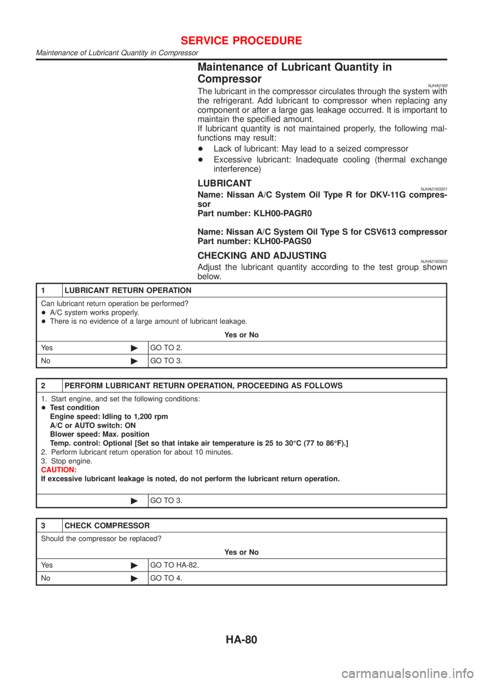
Maintenance of Lubricant Quantity in
Compressor
NJHA0160The lubricant in the compressor circulates through the system with
the refrigerant. Add lubricant to compressor when replacing any
component or after a large gas leakage occurred. It is important to
maintain the specified amount.
If lubricant quantity is not maintained properly, the following mal-
functions may result:
+Lack of lubricant: May lead to a seized compressor
+Excessive lubricant: Inadequate cooling (thermal exchange
interference)
LUBRICANTNJHA0160S01Name: Nissan A/C System Oil Type R for DKV-11G compres-
sor
Part number: KLH00-PAGR0
Name: Nissan A/C System Oil Type S for CSV613 compressor
Part number: KLH00-PAGS0
CHECKING AND ADJUSTINGNJHA0160S02Adjust the lubricant quantity according to the test group shown
below.
1 LUBRICANT RETURN OPERATION
Can lubricant return operation be performed?
+A/C system works properly.
+There is no evidence of a large amount of lubricant leakage.
YesorNo
Ye s©GO TO 2.
No©GO TO 3.
2 PERFORM LUBRICANT RETURN OPERATION, PROCEEDING AS FOLLOWS
1. Start engine, and set the following conditions:
+Test condition
Engine speed: Idling to 1,200 rpm
A/C or AUTO switch: ON
Blower speed: Max. position
Temp. control: Optional [Set so that intake air temperature is 25 to 30ÉC (77 to 86ÉF).]
2. Perform lubricant return operation for about 10 minutes.
3. Stop engine.
CAUTION:
If excessive lubricant leakage is noted, do not perform the lubricant return operation.
©GO TO 3.
3 CHECK COMPRESSOR
Should the compressor be replaced?
YesorNo
Ye s©GO TO HA-82.
No©GO TO 4.
SERVICE PROCEDURE
Maintenance of Lubricant Quantity in Compressor
HA-80
Page 2495 of 2898
5. If a leak detector detects a leak, verify at least once by blow-
ing compressed air into area of suspected leak, then repeat
check as outlined above.
6. Do not stop when one leak is found. Continue to check for
additional leaks at all system components.
If no leaks are found, perform steps7-10.
7. Start engine.
8. Set the heater A/C control as follows:
1) A/C switch ON.
2) Face mode
3) Recirculation position
4) Max cold temperature
5) Fan speed high
9. Run engine at 1,500 rpm for at least 2 minutes.
10. Turn engine off and perform leak check again following steps
4 through 6 above.
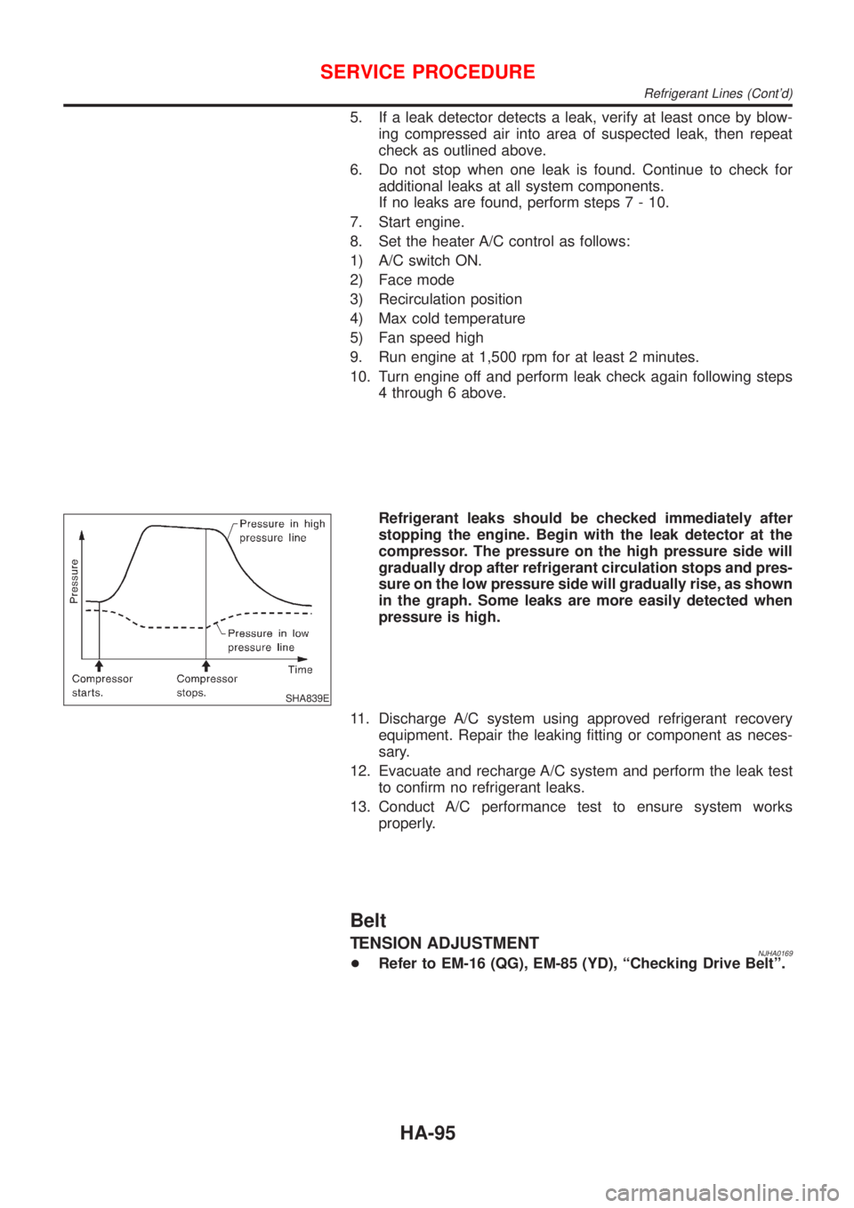
SHA839E
Refrigerant leaks should be checked immediately after
stopping the engine. Begin with the leak detector at the
compressor. The pressure on the high pressure side will
gradually drop after refrigerant circulation stops and pres-
sure on the low pressure side will gradually rise, as shown
in the graph. Some leaks are more easily detected when
pressure is high.
11. Discharge A/C system using approved refrigerant recovery
equipment. Repair the leaking fitting or component as neces-
sary.
12. Evacuate and recharge A/C system and perform the leak test
to confirm no refrigerant leaks.
13. Conduct A/C performance test to ensure system works
properly.
Belt
TENSION ADJUSTMENTNJHA0169+Refer to EM-16 (QG), EM-85 (YD), ªChecking Drive Beltº.
SERVICE PROCEDURE
Refrigerant Lines (Cont'd)
HA-95
Page 2504 of 2898
NVH troubleshooting (SU) ........................ SU-16
NVH troubleshooting (CL) ........................... CL-4
NVIS (Nissan vehicle immobiliser sys-
tem) precautions ....................................... GI-3
Neutral position switch .................... EC-437, 536
O
Oil pan (engine) .................................. EM-20, 89
Oil pressure (engine) ............................ LC-5, 28
Oil pump (A/T) ......................................... AT-384
Oil pump (engine) ................................. LC-5, 28
Oil pump regulator valve (engine) ......... LC-8, 30
Oil seal replacement (engine) .................. EM-32
On board diagnostic system ............. EC-59, 627
Operating cylinder (clutch) ........................ CL-14
Overdrive control switch .......................... AT-341
Overrun clutch .......................................... AT-412
P
P/ANT - Wiring diagram .......................... EL-282
PCV (positive crankcase
ventilation) ..................................... EC-39, 613
PGC/V - Wiring diagram ................. EC-366, 505
PNP/SW - Wiring diagram ...... EC-439, 537, 826
POWER - Wiring diagram ................... EL-11, 28
PST/SW - Wiring diagram ....................... EC-568
Park/Neutral position switch ... EC-437, 536, 826
Park/neutral position switch (A/T) ............ AT-183
Park/neutral position switch (M/T) ............ MT-21
Parking brake control ................................ BR-47
Parking lamp .............................................. EL-81
Piston assembly ............................... EM-62, 155
Piston pin inspection ........................ EM-56, 145
Piston ring inspection ....................... EM-56, 145
Piston to bore clearance .................. EM-58, 147
Power antenna ........................................ EL-282
Power door lock ....................................... EL-314
Power door mirror .................................... EL-294
Power steering fluid level ............................ ST-7
Power steering gear .................................. ST-16
Power steering hydraulic pressure .............. ST-9
Power steering oil pressure switch ......... EC-567
Power steering oil pump ............................ ST-25
Power steering system bleeding ................. ST-8
Power supply routing ................................. EL-10
Power window ......................................... EL-298
Precautions (General) .................................. GI-4
Pressure plate - See Clutch cover ............ CL-22
Priming pump .................................. EC-625, 641
Q
Quick-glow system .................................. EC-806
R
RR02 - Wiring diagram .......... EC-261, 270, 278,
286, 463
RR02/H - Wiring diagram ............... EC-293, 470
Radiator ............................................... LC-16, 42
Radio - See Audio ................................... EL-258
Rear air spoiler .......................................... BT-47
Rear axle (disc brake type) ....................... AX-24
Rear axle ................................................... AX-22
Rear bumper .............................................. BT-10
Rear combination lamp removal and
installation .............................................. BT-47
Rear disc brake .................................. BR-35, 43
Rear door ................................................... BT-16
Rear drum brake ....................................... BR-31
Rear heated oxygen sensor (HO2S)
heater .......................................... EC-291, 469
Rear heated oxygen sensor (HO2S) ..... EC-258,
267, 275, 284, 462
Rear seat belt ............................................ RS-11
Rear seat ................................................... BT-60
Rear suspension ....................................... SU-16
Rear window defogger ............................ EL-240
Rear window .............................................. BT-71
Refrigerant connection precaution .............. HA-3
Refrigerant general precaution ................... HA-2
Refrigerant lines ........................................ HA-91
Refrigeration cycle .................................... HA-13
Release bearing (clutch) ..................... CL-17, 20
Removal and installation (A/T) ................ AT-354
Reverse clutch ......................................... AT-403
Reverse idler shaft (M/T) .............. MT-30, 54, 93
Reverse lamp switch (M/T) - See
Back-up lamp switch (M/T) ................... MT-21
Reverse main gear (M/T) ............. MT-31, 55, 93
Road wheel size ......................................... GI-43
Roof trim .................................................... BT-43
Room lamp - See Interior lamp ............... EL-115
S
S/LOCK - Wiring diagram ............... EL-318, 335,
352, 372
S/SIG - Wiring diagram ........................... EC-558
SAE J1930 terminology list ........................ GI-50
SHIFT - Wiring diagram ........................... AT-344
SROOF - Wiring diagram ........................ EL-292
SRS - See Supplemental Restraint
System ................................................... RS-20
START - Wiring diagram ........................... SC-14
STOP/L - Wiring diagram .................... EL-85, 86
SWL/V - Wiring diagram ................. EC-399, 475
Seal - See Exterior .................................... BT-47
Seat belt pre-tensioner disposal ............... RS-40
Seat belt pre-tensioner ............................... RS-3
Seat belt, front ............................................ RS-5
Seat belt, rear ............................................ RS-11
Seat, front .................................................. BT-56
ALPHABETICAL INDEX
IDX-6
Page 2505 of 2898
Seat, rear ................................................... BT-60
Self-diagnostic results ....................... EC-74, 628
Shift control components (M/T) .... MT-32, 56, 94
Shift fork (M/T) .............................. MT-32, 56, 94
Shift lever .................................................. MT-29
Shift lock system ...................................... AT-343
Shift schedule .......................................... AT-470
Shift solenoid valve A (A/T) ..... AT-204, 209, 222
Shift solenoid valve B (A/T) ............. AT-204, 209
Shock absorber (front) .............................. SU-10
Shock absorber (rear) ............................... SU-21
Side air bag ........................................ RS-36, 38
Side trim .................................................... BT-31
Spare tire size ............................................ GI-43
Speedometer ........................................... EL-144
Spiral cable ............................................... RS-29
Spot lamp ................................................ EL-141
Spring (Wheelarch) height .......................... SU-6
Stabilizer bar (front) ................................... SU-11
Stall test (A/T) ............................................ AT-80
Standardized relay ....................................... EL-8
Start signal ...................................... EC-557, 823
Starter ....................................................... SC-18
Starting system ......................................... SC-13
Steering linkage ......................................... ST-16
Steering switch .......................................... EL-59
Steering wheel and column ....................... ST-11
Steering wheel play ..................................... ST-6
Steering wheel turning force ....................... ST-8
Stop lamp .................................................. EL-85
Striking rod (M/T) .......................... MT-32, 56, 94
Strut (front) .................................................. SU-9
Strut (rear) ................................................. SU-20
Sub-gear (M/T) ................................... MT-31, 55
Sunroof, electric ....................................... EL-292
Sunroof ...................................................... BT-63
Super lock ................................................ EL-349
Supplemental Restraint System ............... RS-20
Supplemental restraint system - Wiring
diagram .................................................. RS-53
Swirl control valve control solenoid
valve ............................................ EC-399, 475
Symbols and abbreviations ........................ GI-10
Symptom matrix chart ..................... EC-155, 646
Synchronizer (M/T) ....................... MT-31, 55, 93
System readiness test (SRT) code ........... EC-62
T
TCM circuit diagram ................................... AT-17
TCM inspection table ............................... AT-119
TFTS - Wiring diagram ........................... EC-315
TP/SW - Wiring diagram ................. EC-387, 521
TPS - Wiring diagram ............................. EC-210
TURN - Wiring diagram ........................... EL-103
Tachometer .............................................. EL-144
Tail lamp .................................................... EL-81
Tank fuel temperature sensor ................. EC-313
Thermostat .......................................... LC-15, 41Three way catalyst precautions ................... GI-6
Three way catalyst .................................. EC-359
Throttle position sensor (TPS) ................ EC-207
Throttle position sensor
adjustment ................................... EC-100, 128
Throttle position switch ........... AT-141, 267, 341,
EC-385, 520
Throwout bearing - See Clutch release
bearing ............................................. CL-17, 20
Tie-rod ball joints ....................................... ST-20
Tie-rod ........................................................ ST-16
Tightening torque of standard bolts ........... GI-49
Timing chain ....................................... EM-23, 94
Tire size ...................................................... GI-43
Torque converter installation .................... AT-355
Tow truck towing ........................................ GI-47
Transmission case (M/T) .............. MT-30, 54, 92
Tread-FR&RR (Dimensions) ...................... GI-43
Trim ............................................................ BT-31
Trouble diagnoses ...................................... GI-31
Trunk lid finisher ........................................ BT-45
Trunk lid opener - See Trunk lid ................ BT-10
Trunk lid trim .............................................. BT-45
Trunk lid ..................................................... BT-10
Trunk room lamp ..................................... EL-141
Trunk room trim ......................................... BT-45
Turn signal lamp ........................................ EL-96
Two trip detection logic ............................. EC-59
Two-pole lift ................................................ GI-46
U
Under body ................................................ BT-80
V
VSS - Wiring diagram ..................... EC-372, 701
Vacuum hose (brake system) ................... BR-22
Vacuum hose drawing (Engine control) .... EC-30
Vacuum pump ........................................... BR-23
Valve clearance ................................ EM-44, 133
Valve guide ....................................... EM-39, 124
Valve lifter ................................................. EM-43
Valve seat ......................................... EM-41, 126
Valve spring ...................................... EM-42, 128
Vehicle speed sensor (VSS) ........... EC-370, 701
Viscosity number (SAE) ............................ MA-17
Viscous coupling (FF M/T) ........................ MT-93
W
WARN - Wiring diagram .......................... EL-190
WIP/R - Wiring diagram .................. EL-225, 227
WIPER - Wiring diagram ................. EL-217, 220
Warning chime ......................................... EL-197
Warning lamps ......................................... EL-184
Washer, front ........................................... EL-215
ALPHABETICAL INDEX
IDX-7