Page 2835 of 4770
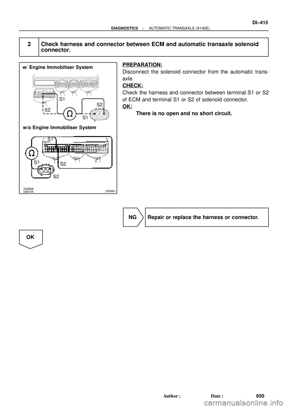
D00104 D00958D00991
w/ Engine Immobiliser System
w/o Engine Immobiliser SystemS2S1
S1S2
S1
S2 S1
S2
± DIAGNOSTICSAUTOMATIC TRANSAXLE (A140E)
DI±415
650 Author�: Date�:
2 Check harness and connector between ECM and automatic transaxle solenoid
connector.
PREPARATION:
Disconnect the solenoid connector from the automatic trans-
axle.
CHECK:
Check the harness and connector between terminal S1 or S2
of ECM and terminal S1 or S2 of solenoid connector.
OK:
There is no open and no short circuit.
NG Repair or replace the harness or connector.
OK
Page 2840 of 4770
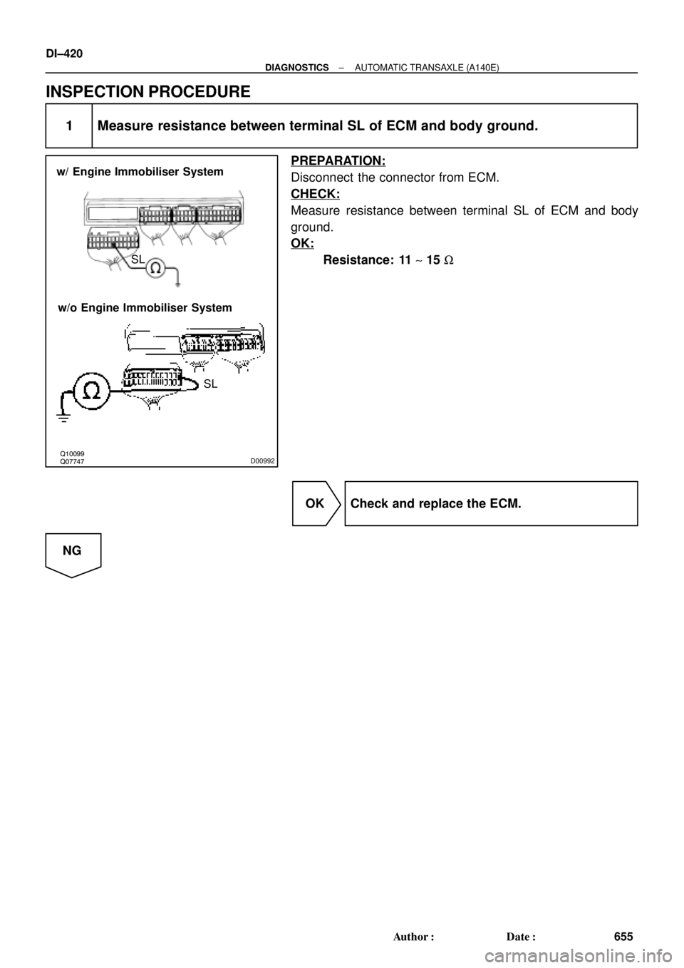
Q07747 Q10099D00992
w/ Engine Immobiliser System
w/o Engine Immobiliser System
SL SL
DI±420
± DIAGNOSTICSAUTOMATIC TRANSAXLE (A140E)
655 Author�: Date�:
INSPECTION PROCEDURE
1 Measure resistance between terminal SL of ECM and body ground.
PREPARATION:
Disconnect the connector from ECM.
CHECK:
Measure resistance between terminal SL of ECM and body
ground.
OK:
Resistance: 11 ~ 15 W
OK Check and replace the ECM.
NG
Page 2841 of 4770
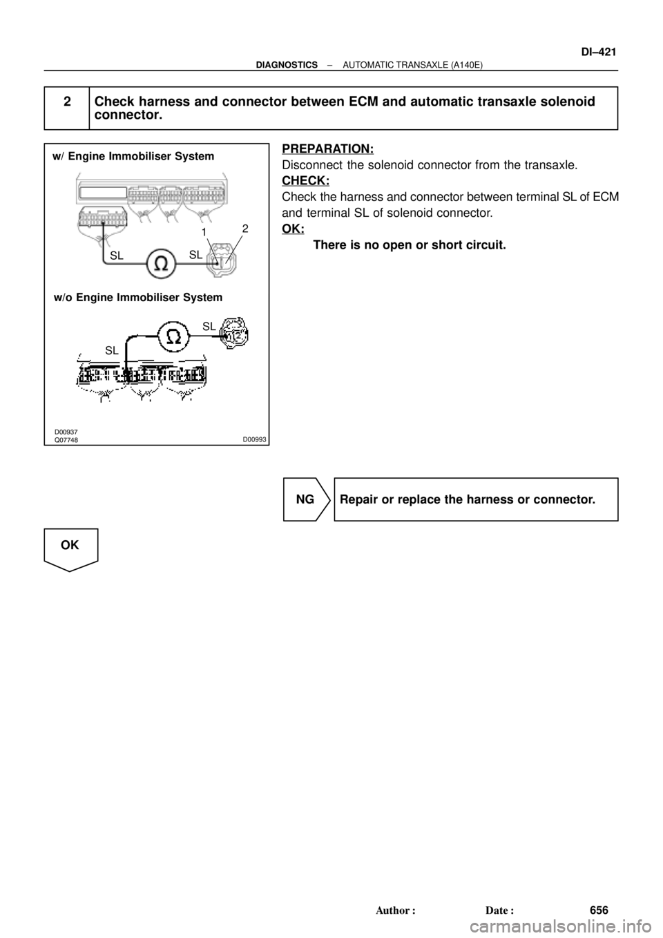
Q07748 D00937D00993
w/ Engine Immobiliser System
w/o Engine Immobiliser System
SL SL
SLSL12
± DIAGNOSTICSAUTOMATIC TRANSAXLE (A140E)
DI±421
656 Author�: Date�:
2 Check harness and connector between ECM and automatic transaxle solenoid
connector.
PREPARATION:
Disconnect the solenoid connector from the transaxle.
CHECK:
Check the harness and connector between terminal SL of ECM
and terminal SL of solenoid connector.
OK:
There is no open or short circuit.
NG Repair or replace the harness or connector.
OK
Page 2846 of 4770
(+) (+)
(±)
Position
P, N
R
D
2
LNSW±Body
groundR±Body
ground2±Body
groundL±Body
grou")
D00043 Q08479BE3840D00994
w/ Engine Immobiliser System
w/o Engine Immobiliser SystemON
NSW
LL
2
R
NSWR
2
(±)(+) (+)
(±)
Position
P, N
R
D
2
LNSW±Body
groundR±Body
ground2±Body
groundL±Body
ground
0 V
0 V0 V0 V
0 V
0 V
0 V 0 V
0 V
0 V 0 V
0 V
0 V 9 ~ 14 V*
9 ~ 14 V
9 ~ 14 V
9 ~ 14 V9 ~ 14 V
9 ~ 14 V 9 ~ 14 V*
DI±426
± DIAGNOSTICSAUTOMATIC TRANSAXLE (A140E)
661 Author�: Date�:
INSPECTION PROCEDURE
1 Read PNP, REVERSE, 2ND and LOW signals.
When using TOYOTA hand±held tester:
PREPARATION:
(a) Remove the DLC3 cover.
(b) Connect a TOYOTA hand±held tester to the DLC3.
(c) Turn the ignition switch ON and TOYOTA hand±held tes-
ter main switch ON.
CHECK:
Shift the shift lever into the P, R, N, 2 and L positions, and read
the PNP, REVERSE, 2ND and LOW signals on the TOYOTA
hand±held tester.
OK:
Shift positionSignal
22ND OFF " ON
LLOW OFF " ON
RREVERSE OFF " ON
P, NPNP OFF " ON
When not using TOYOTA hand±held tester:
PREPARATION:
Turn the ignition switch ON.
CHECK:
Measure voltage between terminals NSW, 2, L and R of ECM
and body ground when the shift lever is shifted in the following
positions.
OK:
HINT:
The voltage will drop slightly due to lighting up of the back up
light.
OK Proceed to next circuit inspection shown on
matrix chart (See page DI±405).
NG
Page 2849 of 4770
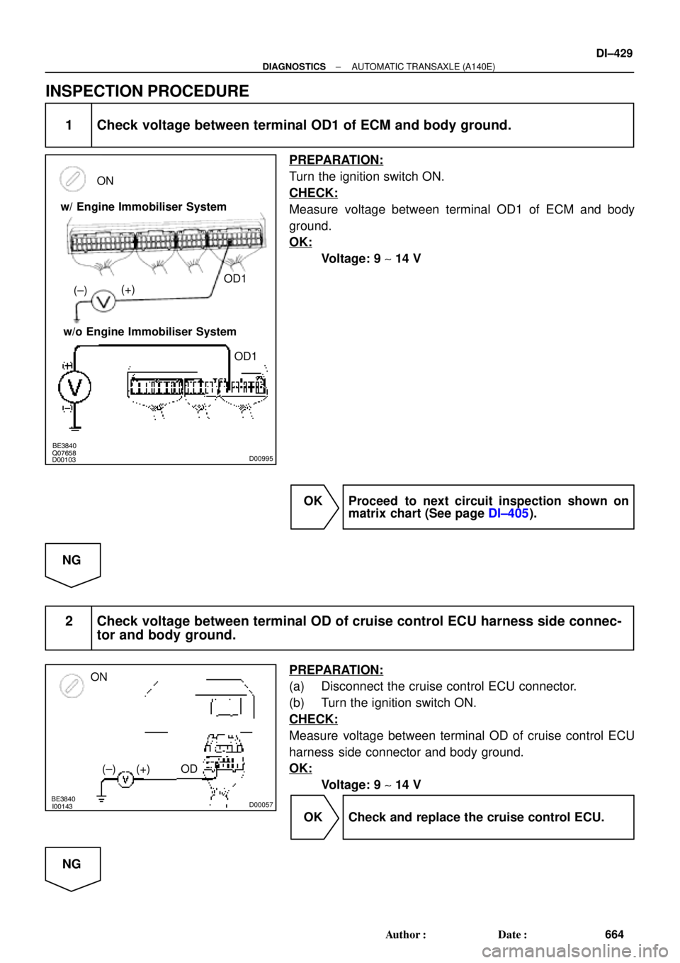
Q07658
D00103BE3840D00995
w/ Engine Immobiliser System
w/o Engine Immobiliser SystemON
OD1
OD1 (+)
(±)
BE3840
I00143D00057
ON
OD (+) (±)
± DIAGNOSTICSAUTOMATIC TRANSAXLE (A140E)
DI±429
664 Author�: Date�:
INSPECTION PROCEDURE
1 Check voltage between terminal OD1 of ECM and body ground.
PREPARATION:
Turn the ignition switch ON.
CHECK:
Measure voltage between terminal OD1 of ECM and body
ground.
OK:
Voltage: 9 ~ 14 V
OK Proceed to next circuit inspection shown on
matrix chart (See page DI±405).
NG
2 Check voltage between terminal OD of cruise control ECU harness side connec-
tor and body ground.
PREPARATION:
(a) Disconnect the cruise control ECU connector.
(b) Turn the ignition switch ON.
CHECK:
Measure voltage between terminal OD of cruise control ECU
harness side connector and body ground.
OK:
Voltage: 9 ~ 14 V
OK Check and replace the cruise control ECU.
NG
Page 2853 of 4770
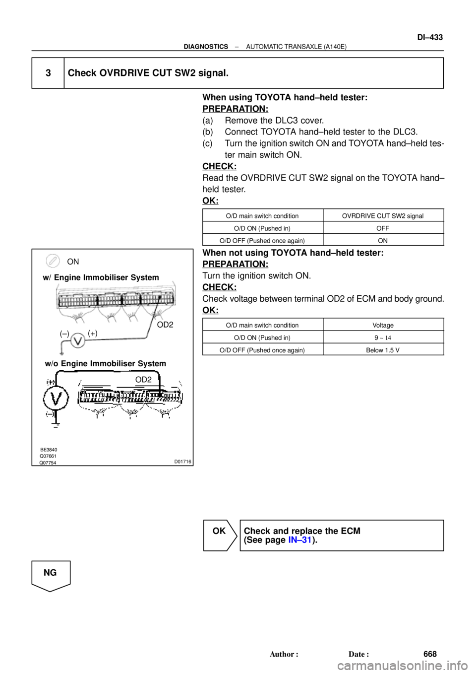
Q07754Q07661BE3840D01716
ON
(+)
OD2
(±) w/ Engine Immobiliser System
w/o Engine Immobiliser System
OD2
± DIAGNOSTICSAUTOMATIC TRANSAXLE (A140E)
DI±433
668 Author�: Date�:
3 Check OVRDRIVE CUT SW2 signal.
When using TOYOTA hand±held tester:
PREPARATION:
(a) Remove the DLC3 cover.
(b) Connect TOYOTA hand±held tester to the DLC3.
(c) Turn the ignition switch ON and TOYOTA hand±held tes-
ter main switch ON.
CHECK:
Read the OVRDRIVE CUT SW2 signal on the TOYOTA hand±
held tester.
OK:
O/D main switch conditionOVRDRIVE CUT SW2 signal
O/D ON (Pushed in)OFF
O/D OFF (Pushed once again)ON
When not using TOYOTA hand±held tester:
PREPARATION:
Turn the ignition switch ON.
CHECK:
Check voltage between terminal OD2 of ECM and body ground.
OK:
O/D main switch conditionVoltage
O/D ON (Pushed in)9 ~ 14
O/D OFF (Pushed once again)Below 1.5 V
OK Check and replace the ECM
(See page IN±31).
NG
Page 2858 of 4770

673 Author�: Date�:
PRE±CHECK
1. DIAGNOSIS SYSTEM
(a) Description
�When troubleshooting OBD II")
FI0534
DI02E±02
S05335
TOYOTA hand±held tester
DLC3
DI±438
± DIAGNOSTICSAUTOMATIC TRANSAXLE (A541E)
673 Author�: Date�:
PRE±CHECK
1. DIAGNOSIS SYSTEM
(a) Description
�When troubleshooting OBD II vehicles, the only dif-
ference from the usual troubleshooting procedure
is that you connect to the vehicle an OBD II scan
tool complying with SAE J1987 or TOYOTA hand±
held tester, and read off various data output from
the vehicle's ECM.
OBD II regulations require that the vehicle's on±
board computer lights up the Malfunction Indicator
Lamp (MIL) on the instrument panel when the com-
puter detects a malfunction in the computer itself or
in drive system components which affect vehicle
emissions. In addition to the MIL lighting up when
a malfunction is detected, the applicable DTCs pre-
scribed by SAE J2012 are recorded in the ECM
memory. (See page DI±211)
If the malfunction only occurs in 3 trips, the MIL goes
off but the DTCs remain recorded in the ECM
memory.
�To check the DTCs, connect an OBD II scan tool or
TOYOTA hand±held tester to DLC3 on the vehicle.
The OBD II scan tool or TOYOTA hand±held tester
also enables you to erase the DTCs and check
freeze frame data and various forms of engine data
(For instruction book).
DTCs include SAE controlled codes and Manufac-
turer controlled codes.
SAE controlled codes must be set as prescribed by
the SAE, while Manufacturer controlled codes can
be set freely by the manufacturer within the pre-
scribed limits (See DTC chart on page DI±449).
Page 2860 of 4770

675 Author�: Date�:
2. INSPECT DIAGNOSIS (NORMAL MODE)
(a) Check the MIL.
(1) The MIL comes on when the ig")
FI0534
S05335
TOYOTA hand±held tester
DLC3
DI±440
± DIAGNOSTICSAUTOMATIC TRANSAXLE (A541E)
675 Author�: Date�:
2. INSPECT DIAGNOSIS (NORMAL MODE)
(a) Check the MIL.
(1) The MIL comes on when the ignition switch is turned
ON and the engine is not running.
HINT:
If the MIL does not light up, troubleshoot the combination meter
(See page BE±2).
(2) When the engine is started, the MIL should go off.
If the lamp remains on, the diagnosis system has
detected a malfunction or abnormality in the sys-
tem.
(b) Check the DTC.
NOTICE:
TOYOTA hand±held tester only:
When the diagnostic system is switched from normal mode
to check mode, it erases all DTCs and freeze frame data re-
corded in normal mode. So before switching modes, al-
ways check the DTCs and freeze frame data, and note them
down.
(1) Prepare an OBD II scan tool (complying with SAE
J1978) or TOYOTA hand±held tester.
(2) Connect the OBD II scan tool or TOYOTA hand±
held tester to DLC3 at the lower of the instrument
panel.
(3) Turn the ignition switch ON and turn the OBD II scan
tool or TOYOTA hand±held tester switch ON.
(4) Use the OBD II scan tool or TOYOTA hand±held
tester to check the DTCs and freeze frame data and
note them down (For operating instructions, see the
OBD II scan tool's instruction book).
(5) See page DI±449 to confirm the details of the DTCs.
NOTICE:
When simulating symptoms with an OBD II scan tool (ex-
cluding TOYOTA hand±held tester) to check the DTCs, use
normal mode. For codes on the DTCs chart subject to º2
trip detection logicº, turn the ignition switch off after the
symptoms have been simulated the 1st time. Them repeat
the simulation process again. When the program has DTCs
are recorded in the ECM.