Page 2803 of 4770
± DIAGNOSTICSENGINE (1MZ±FE)
DI±383
618 Author�: Date�:
3 Check for vacuum tank (See page SF±60).
NG Repair or replace.
OK
Check and replace ECM (See page IN±31).
Page 2805 of 4770
± DIAGNOSTICSENGINE (1MZ±FE)
DI±385
620 Author�: Date�:
INSPECTION PROCEDURE
HINT:
This diagnostic chart is based on the premise that the engine is cranked normally. If the engine is not
cranked, proceed to the problem symptoms table on page DI±221.
TOYOTA hand±held tester
1 Connect TOYOTA hand±held tester, and check STA signal.
PREPARATION:
(a) Connect the TOYOTA hand±held tester to the DLC3.
(b) Turn the ignition switch ON and push the TOYOTA hand±held tester main switch ON.
CHECK:
Read STA signal on the TOYOTA hand±held tester while starter operates.
OK:
Ignition switch positionONSTART
STA signalOFFON
OK Proceed to next circuit inspection shown on
problem symptom table (See page DI±221).
NG
2 Check for open in harness and connector between ECM and starter relay
(See page IN±31).
NG Repair or replace or connector.
OK
Check and replace ECM (See page IN±31).
Page 2806 of 4770
A07152
ON
STA (+)
DI±386
± DIAGNOSTICSENGINE (1MZ±FE)
621 Author�: Date�:
OBD II scan tool (excluding TOYOTA hand±held tester)
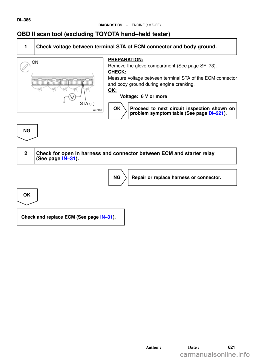
1 Check voltage between terminal STA of ECM connector and body ground.
PREPARATION:
Remove the glove compartment (See page SF±73).
CHECK:
Measure voltage between terminal STA of the ECM connector
and body ground during engine cranking.
OK:
Voltage: 6 V or more
OK Proceed to next circuit inspection shown on
problem symptom table (See page DI±221).
NG
2 Check for open in harness and connector between ECM and starter relay
(See page IN±31).
NG Repair or replace harness or connector.
OK
Check and replace ECM (See page IN±31).
Page 2809 of 4770

DI±389
624 Author�: Date�:
PRE±CHECK
1. DIAGNOSIS SYSTEM
(a) Description
�When troubleshooting OBD II")
DI02W±02
FI0534
S05335
TOYOTA hand±held tester
DLC3
± DIAGNOSTICSAUTOMATIC TRANSAXLE (A140E)
DI±389
624 Author�: Date�:
PRE±CHECK
1. DIAGNOSIS SYSTEM
(a) Description
�When troubleshooting OBD II vehicles, the only dif-
ference from the usual troubleshooting procedure
is that you connect an OBD II scan tool complying
with SAE J1987 or TOYOTA hand±held tester to the
vehicle, and read off various data output from the
vehicle's ECM.
OBD II regulations require that the vehicle's on±
board computer lights up the Malfunction Indicator
Lamp (MIL) on the instrument panel when the com-
puter detects a malfunction in the computer itself or
in drive system components which affect vehicle
emissions. In addition to the MIL lighting up when
a malfunction is detected, the applicable DTCs pre-
scribed by SAE J2012 are recorded in the ECM
memory (See page DI±16).
If the malfunction only occurs in 3 trips, the MIL goes
off but the DTCs remain recorded in the ECM
memory.
�To check the DTCs, connect an OBD II scan tool or
TOYOTA hand±held tester to DLC3 on the vehicle.
The OBD II scan tool or TOYOTA hand±held tester
also enables you to erase the DTCs and check
freeze frame data and various forms of engine data
(For instruction book).
DTCs include SAE controlled codes and Manufac-
turer controlled codes.
SAE controlled codes must be set as the codes pre-
scribed by the SAE, while Manufacturer controlled
codes can be set freely by the manufacturer within
the prescribed limits.
(See DTC chart on page DI±401)
Page 2811 of 4770

DI±391
626 Author�: Date�:
2. INSPECT DIAGNOSIS (NORMAL MODE)
(a) Check the MIL.
(1) The MIL comes on when the ig")
FI0534
S05335
TOYOTA hand±held tester
DLC3
± DIAGNOSTICSAUTOMATIC TRANSAXLE (A140E)
DI±391
626 Author�: Date�:
2. INSPECT DIAGNOSIS (NORMAL MODE)
(a) Check the MIL.
(1) The MIL comes on when the ignition switch is turned
ON and the engine is not running.
HINT:
If the MIL does not light up, troubleshoot the combination meter
(See page BE±47).
(2) When the engine is started, the MIL should go off.
If the lamp remains on, the diagnosis system has
detected a malfunction or abnormality in the sys-
tem.
(b) Check the DTC.
NOTICE:
(TOYOTA hand±held tester only): When the diagnostic sys-
tem is switched from normal mode to check mode, it erases
all DTCs and freeze frame data recorded in normal mode.
So before switching modes, always check the DTCs and
freeze frame data, and note them down.
(1) Prepare an OBD II scan tool (complying with SAE
J1978) or TOYOTA hand±held tester.
(2) Connect the OBD II scan tool or TOYOTA hand±
held tester to DLC3 at the lower portion of the instru-
ment panel.
(3) Turn the ignition switch ON and turn the OBD II scan
tool or TOYOTA hand±held tester switch ON.
(4) Use the OBD II scan tool or TOYOTA hand±held
tester to check the DTCs and freeze frame data and
note them down (For operating instructions, see the
OBD II scan tool's instruction book).
(5) See page DI±401 to confirm the details of the DTCs.
NOTICE:
When simulating symptoms with an OBD II scan tool (ex-
cluding TOYOTA hand±held tester) to check the DTCs, use
normal mode. For codes on the DTCs chart subject to º2
trip detection logicº, turn the ignition switch off after the
symptoms have been simulated the 1st time. Then repeat
the simulation process again. When the program has
DTCs, the DTCs are recorded in the ECM.
Page 2812 of 4770

627 Author�: Date�:
3. INSPECT DIAGNOSIS (CHECK MODE)
HINT:
TOYOTA hand±held te")
S05335
TOYOTA hand±held tester
DLC3
BR3904
ON
OFF0.13 sec.
0.13 sec. DI±392
± DIAGNOSTICSAUTOMATIC TRANSAXLE (A140E)
627 Author�: Date�:
3. INSPECT DIAGNOSIS (CHECK MODE)
HINT:
TOYOTA hand±held tester only: Compared to the Normal
mode, the Check mode has high sensing ability to detect mal-
functions. Furthermore, the same diagnostic items which are
detected in Normal mode can also be detected in Check mode.
(a) Check the DTC.
(1) Check the initial conditions.
�Battery positive voltage 11 V or more
�Throttle valve fully closed
�Transaxle in P position
�Air conditioning switched off
(2) Turn the ignition switch OFF.
(3) Prepare a TOYOTA hand±held tester.
(4) Connect the TOYOTA hand±held tester to DLC3 at
the lower side of the instrument panel.
(5) Turn the ignition switch ON and switch the TOYOTA
hand±held tester ON.
(6) Switch the TOYOTA hand±held tester from Normal
mode to Check mode (Check that the MIL flashes).
(7) Start the engine (MIL goes out after the engine
starts).
(8) Simulate the conditions of the malfunction de-
scribed by the customer.
NOTICE:
Leave the ignition switch ON until you have checked the
DTCs, etc.
(9) After simulating the malfunction conditions, use the
TOYOTA hand±held tester diagnosis selector to
check the DTCs and freeze frame data, etc.
HINT:
Take care not to turn the ignition switch OFF, as turning it off the
diagnosis system switches from Check mode to Normal mode,
so all DTCs, etc. are erased.
(10) After checking the DTC, inspect the applicable cir-
cuit.
Page 2813 of 4770

DI±393
628 Author�: Date�:
(b) Clearance the DTC.
The following actions will erase the DTC and freeze frame
data. Operating an OBD II scan tool (complying w")
± DIAGNOSTICSAUTOMATIC TRANSAXLE (A140E)
DI±393
628 Author�: Date�:
(b) Clearance the DTC.
The following actions will erase the DTC and freeze frame
data. Operating an OBD II scan tool (complying with SAE
J1978) or TOYOTA hand±held tester to erase the codes.
(See the OBD II scan tool's instruction book for operating
instructions.)
4. ROAD TEST
NOTICE:
Perform the test at normal operating ATF temperature 50 ± 80 °C (122 ± 176 °F).
(a) D position test
Shift into the D position and fully depress the accelerator pedal and and check the following points:
(1) Check up±shift operation.
1 " 2, 2 " 3 and 3 " O/D up±shifts take place, at the shift point shown in the automatic shift
schedule (See page SS±54).
HINT:
�O/D Gear Up±shift Prohibition Control (1. Coolant temp. is 50 °C (122 °C) or less. 2. If there is a 10
km/h (6 mph) difference between the set cruise control speed and vehicle speed.)
�O/D Gear Lock±up Prohibition Control (1. Brake pedal is depressed. 2. Coolant temp. is 50 °C
(122 °C) or less.)
(2) Check for shift shock and slip.
Check for shock and slip at the 1 " 2, 2 " 3 and 3 " O/D up±shifts.
(3) Check for abnormal noises and vibration.
Run at the D position lock±up or O/D gear and check for abnormal noises and vibration.
HINT:
The check for the cause of abnormal noises and vibration must be done very thoroughly as it could also be
due to loss of balance in the differential or torque converter clutch, etc.
(4) Check kick±down operation.
While running in the D position, 2nd, 3rd and O/D gears, check to see that the possible kick±down
vehicle speed limits for 2 " 1, 3 " 2 and O/D " 3 kick±downs conform to those indicated on
the automatic shift schedule (See page SS±54).
(5) Check abnormal shock and slip at kick±down.
(6) Check the lock±up mechanism.
�Drive in D position, O/D gear, at a steady speed (lock±up ON) of about 75 km/h (47 mph).
�Lightly depress the accelerator pedal and check that the engine speed does not change
abruptly.
If there is a big jump in engine speed, there is no lock±up.
(b) 2 position test
Shift into the 2 position and fully depress the accelerator pedal and check the following points:
(1) Check up±shift operation.
Check to see that the 1 " 2 up±shift takes place and that the shift point conforms to the automatic
shift schedule (See page SS±54).
HINT:
There is no O/D up±shift and lock±up in the 2 position.
(2) Check engine braking.
While running in the 2 position and 2nd gear, release the accelerator pedal and check the engine
braking effect.
Page 2814 of 4770

629 Author�: Date�:
(3) Check for abnormal noises during acceleration and deceleration, and for shock at up±shift")
Q00519
AT3417
OK if hot
Add if hot DI±394
± DIAGNOSTICSAUTOMATIC TRANSAXLE (A140E)
629 Author�: Date�:
(3) Check for abnormal noises during acceleration and deceleration, and for shock at up±shift and
down±shift.
(c) L position test
Shift into the 2 position and fully depress the accelerator pedal and check the following points:
(1) Check no up±shift.
While running in the L position, check that there is no up±shift to 2nd gear.
(2) Check engine braking.
While running in the L position, release the accelerator pedal and check the engine braking ef-
fect.
(3) Check for abnormal noises during acceleration and deceleration.
(d) R position test
Shift into the R position and fully depress the accelerator pedal and check for slipping.
CAUTION:
Before conducting this test ensure that the test area is free from people and obstruction.
(e) P position test
Stop the vehicle on a grade (more than 5°) and after shifting into the P position, release the parking
brake. Then, check to see that the parking lock pawl holds the vehicle in place.
5. BASIC INSPECTION
(a) Check the fluid level.
HINT:
�Drive the vehicle so that the engine and transaxle are at
normal operating temperature.
Fluid temp.: 70 ± 80 °C (158 ± 176 °F)
�Only use the COOL range on the dipstick as a rough refer-
ence when the fluid is replaced or the engine does not
run.
(1) Park the vehicle on a level surface and set the park-
ing brake.
(2) With the engine idling and the brake pedal de-
pressed, shift the shift lever into all positions from P
to L position and return to P position.
(3) Pull out the dipstick and wipe it clean.
(4) Push it back fully into the pipe.
(5) Pull it out and check that the fluid level is in the HOT
range.
If the level is not within the range, add new fluid.
Fluid type: ATF D±II or DEXRON®III (DEXRON®II)
NOTICE:
Do not overfill.
(b) Check the fluid condition.
If the level is not within the hot range.