Page 2768 of 4770
DI±348
± DIAGNOSTICSENGINE (1MZ±FE)
583 Author�: Date�:
8 Check injector injection (See page SF±25).
NG Replace injector.
OK
Replace A/F sensors (bank1, 2 sensor1).
9 Perform confirmation driving pattern (See page DI±197).
Go
10 Are there DTC P1133 and/or P1153 being output again ?
YES Check and replace ECM
(See page IN±31).
NO
11 Did vehicle runs out of fuel in the past ?
NO Check for intermittent problems
(See page DI±197).
YES
DTC P1133 and /or P1153 is caused by running out of fuel.
Page 2769 of 4770

HAFR (+)
± DIAGNOSTICSENGINE (1MZ±FE)
DI±349
584 Author�: Date�:
DTC P1135 A/F Sensor Heater Circuit Malfunction
(Bank 1 Sensor 1) (Only for California Spec.)
DTC P1155 A/F Sensor")
A02509
HAFL (+)
HAFR (+)
± DIAGNOSTICSENGINE (1MZ±FE)
DI±349
584 Author�: Date�:
DTC P1135 A/F Sensor Heater Circuit Malfunction
(Bank 1 Sensor 1) (Only for California Spec.)
DTC P1155 A/F Sensor Heater Circuit Malfunction
(Bank 2 Sensor 1) (Only for California Spec.)
CIRCUIT DESCRIPTION
Refer to DTC P0125 (Insufficient Coolant Temp. for Closed Loop Fuel Control (Only for California Spec.))
on page DI±249.
DTC No.DTC Detecting ConditionTrouble Area
P1135
When heater operates, heater current exceeds 8 A
(2 trip detection logic)�Open or in heater circuit of A/F sensors
(bank 1, 2 sensor 1)P1135
P1155Heater current of 0.25 A or less when heater operates
(2 trip detection logic)
(bank 1, 2 sensor 1)
�A/F sensors (bank 1, 2 sensor 1) heater
�ECM
WIRING DIAGRAM
Refer to DTC P0125 (Insufficient Coolant Temp. for Closed Loop Fuel Control (Only for California Spec.))
on page DI±249.
INSPECTION PROCEDURE
HINT:
Read freeze frame data using TOYOTA hand±held tester or OBD II scan tool. Because freeze frame records
the engine conditions when the malfunction is detected, when troubleshooting it is useful for determining
whether the vehicle was running or stopped, the engine warmed up or not, the air±fuel ratio lean or rich, etc.
at the time of the malfunction.
1 Check voltage between terminal HAFR, HAFL of ECM connector and body
ground.
PREPARATION:
(a) Remove glove compartment (See page SF±73).
(b) Turn the ignition switch ON.
CHECK:
Measure voltage between terminals HAFR, HAFL of the ECM
connector and body ground.
OK:
Voltage: 9 ~ 14 V
OK Check and replace ECM (See page IN±31).
NG
DI1K8±04
Page 2770 of 4770
DI±350
± DIAGNOSTICSENGINE (1MZ±FE)
585 Author�: Date�:
2 Check resistance of A/F sensor heaters (bank 1, 2 sensor 1) (See page SF±68).
NG Replace A/F sensors (bank 1, 2 sensor 1).
OK
Check and repair harness or connector between EFI main relay (Marking: EFI) and A/F sensors
(bank 1, 2 sensor 1), and A/F sensors (bank 1, 2 sensor 1) and ECM (See page IN±31).
Page 2772 of 4770
S05723
J18
Junction
Connector
A
A A A AII3B±R
B±R B±R W±R128 3
1K 1C
Ignition
Switch
76
1K
1BB±R
G
B±R
B±R Y
LIgnition Coil
Spark Plug
No.1
No.2
No.3
11
12
2
2
ED
BR
3 2 1
10
9
7
6
5
4
W±R LG±B
BR±Y
IgniterECM
IGT1
IGT2
IGT3
IGF5 VInstrument
Panel J/B
E1125
E1113
E1112
E1111GR
B±R
5
5
W±R
Engine Room J/B
2L4
AM2
2A1
B
Fusible
Link
Block 1
1
F6
B±GFL
MAIN
Battery
F4
Instrument
Panel J/B
DI±352
± DIAGNOSTICSENGINE (1MZ±FE)
587 Author�: Date�:
WIRING DIAGRAM
INSPECTION PROCEDURE
HINT:
Read freeze frame data using TOYOTA hand±held tester or OBD II scan tool. Because freeze frame records
the engine conditions when the malfunction is detected, when troubleshooting it is useful for determining
whether the vehicle was running or stopped, the engine warmed up or not, the air±fuel ratio lean or rich, etc.
at the time of the malfunction.
1 Check spark plug and spark of misfiring cylinder (See page DI±276).
NG Go to step 4.
OK
Page 2773 of 4770
A02033
ON
IGF (+)
± DIAGNOSTICSENGINE (1MZ±FE)
DI±353
588 Author�: Date�:
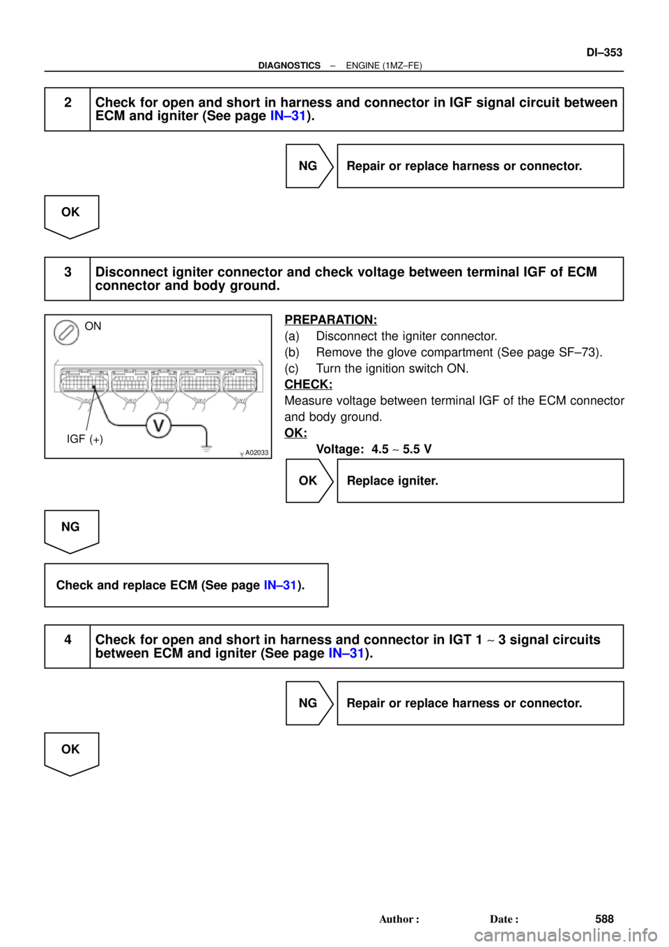
2 Check for open and short in harness and connector in IGF signal circuit between
ECM and igniter (See page IN±31).
NG Repair or replace harness or connector.
OK
3 Disconnect igniter connector and check voltage between terminal IGF of ECM
connector and body ground.
PREPARATION:
(a) Disconnect the igniter connector.
(b) Remove the glove compartment (See page SF±73).
(c) Turn the ignition switch ON.
CHECK:
Measure voltage between terminal IGF of the ECM connector
and body ground.
OK:
Voltage: 4.5 ~ 5.5 V
OK Replace igniter.
NG
Check and replace ECM (See page IN±31).
4 Check for open and short in harness and connector in IGT 1 ~ 3 signal circuits
between ECM and igniter (See page IN±31).
NG Repair or replace harness or connector.
OK
Page 2774 of 4770
 (+) (+)
P20870
IGT1 ~ IGT3 and IGF Signal Waveform
VOLT
5
0
5
0
5
0
5
0IGT1
IGT2
IGT3
IGF
20 msec./Division (Idling)
A02034
START
IGT 3 IGT2 IGT1(+) (+)")
A02034
START
IGT3 IGT2 IGT1(+) (+) (+)
P20870
IGT1 ~ IGT3 and IGF Signal Waveform
VOLT
5
0
5
0
5
0
5
0IGT1
IGT2
IGT3
IGF
20 msec./Division (Idling)
A02034
START
IGT 3 IGT2 IGT1(+) (+) (+)
DI±354
± DIAGNOSTICSENGINE (1MZ±FE)
589 Author�: Date�:
5 Check voltage between terminals IGT 1 ~ 3 of ECM connector and body ground.
PREPARATION:
Remove the glove compartment (See page SF±73).
CHECK:
Measure voltage between terminals IGT 1 ~ 3 of the ECM con-
nector and body ground when engine is cranked.
OK:
Voltage: More than 0.1 V and less than 4.5 V
Reference INSPECTION USING OSCILLOSCOPE
During idling, check waveform between terminals IGT 1 ~ 3,
IGF and E1 of ECM.
HINT:
The correct waveforms are as shown.
NG Check and replace ECM (See page IN±31).
OK
6 Disconnect igniter connector and check voltage between terminals IGT 1 ~ 3 of
ECM connector and body ground.
PREPARATION:
(a) Disconnect the igniter connector.
(b) Remove the glove compartment (See page SF±73).
CHECK:
Measure voltage between terminals IGT 1 ~ 3 of the ECM con-
nector and body ground when engine is cranked.
OK:
Voltage: More than 0.1 V and less than 4.5 V
NG Check and replace ECM (See page IN±31).
OK
Page 2775 of 4770
BE6653
P24329A00124
ON START
9 (+)
± DIAGNOSTICSENGINE (1MZ±FE)
DI±355
590 Author�: Date�:
7 Check voltage between terminal 9 of igniter connector and body ground.
PREPARATION:
Disconnect the igniter connector.
CHECK:
Measure voltage between terminal 9 of igniter connector and
body ground when ignition switch is turned to ºONº and
ºSTARTº position.
OK:
Voltage: 9 ~ 14 V
NG Check and repair igniter power source circuit
(See page IG±1).
OK
8 Check for open and short in harness and connector between ignition switch and
ignition coil, and ignition coil and igniter (See page IN±31).
NG Repair or replace harness or connector.
OK
9 Check ignition coil (See page IG±1).
NG Replace ignition coil.
OK
Page 2776 of 4770
DI±356
± DIAGNOSTICSENGINE (1MZ±FE)
591 Author�: Date�:
10 Check EFI main relay (Marking: EFI) (See page SF±53).
NG Replace EFI main relay (Marking: EFI).
OK
Replace igniter.