Page 2779 of 4770

BE6653S05694
S05742
1
2
± DIAGNOSTICSENGINE (1MZ±FE)
DI±359
594 Author�: Date�:
INSPECTION PROCEDURE
HINT:
�If DTCs ºP0110º (Intake Air Temp. Circuit Malfunction), ºP0115º (Engi")
A00379
ON
1 (+)
BE6653S05694
S05742
1
2
± DIAGNOSTICSENGINE (1MZ±FE)
DI±359
594 Author�: Date�:
INSPECTION PROCEDURE
HINT:
�If DTCs ºP0110º (Intake Air Temp. Circuit Malfunction), ºP0115º (Engine Coolant Temp. Circuit Mal-
function), ºP0120º (Throttle/Pedal Position/Switch ºAº Circuit Malfunction), ºP1410º (EGR Valve Posi-
tion Sensor Circuit Malfunction) are output simultaneously, E2 (Sensor Ground) may be open.
�Read freeze frame data using TOYOTA hand±held tester or OBD II scan tool. Because freeze frame
records the engine conditions when the malfunction is detected, when troubleshooting it is useful for
determining whether the vehicle was running or stopped, the engine warmed up or not, the air±fuel
ratio lean or rich, etc. at the time of the malfunction.
1 Check voltage between terminal VC of wire harness side connector and body
ground.
PREPARATION:
(a) Disconnect the vacuum hose from EGR valve.
(b) Disconnect the EGR valve position sensor connector.
(c) Turn the ignition switch ON.
CHECK:
Measure voltage between terminal 1 of wire harness side con-
nector and body ground.
OK:
Voltage: 4.5 ~ 5.5 V
NG Go to step 4.
OK
2 Check EGR valve position sensor.
PREPARATION:
Disconnect the EGR valve position sensor connector.
CHECK:
Measure resistance between terminals 1 (VC) and 2 (E2) of
EGR valve position sensor.
OK:
Resistance: 1.5 ~ 4.3 kW
NG Replace EGR valve position sensor.
OK
Page 2780 of 4770
A02036
ON
EGLS (+) E2 (±)
DI±360
± DIAGNOSTICSENGINE (1MZ±FE)
595 Author�: Date�:
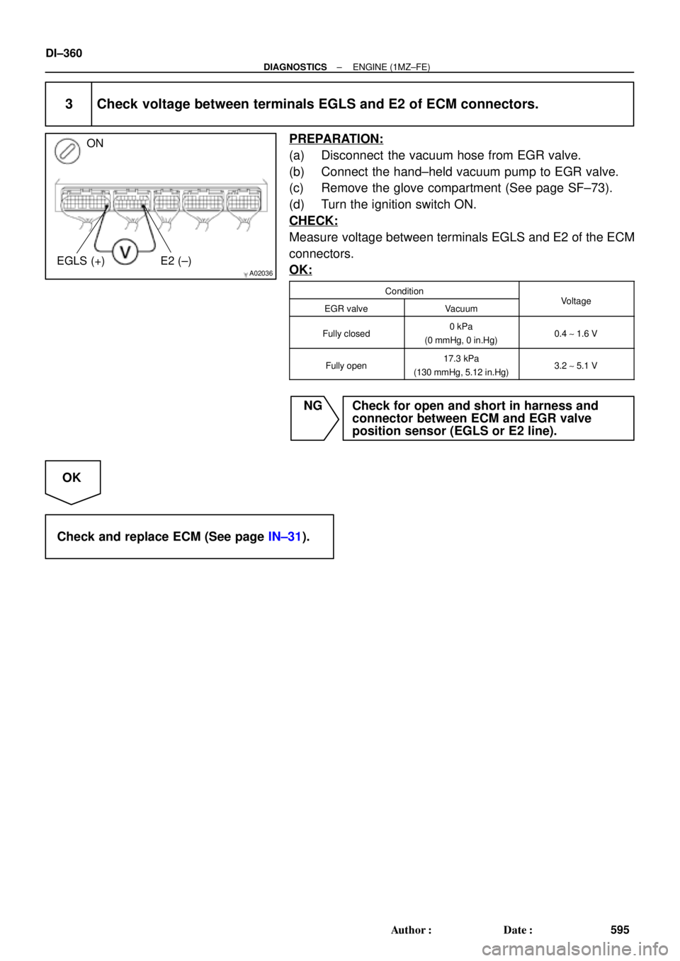
3 Check voltage between terminals EGLS and E2 of ECM connectors.
PREPARATION:
(a) Disconnect the vacuum hose from EGR valve.
(b) Connect the hand±held vacuum pump to EGR valve.
(c) Remove the glove compartment (See page SF±73).
(d) Turn the ignition switch ON.
CHECK:
Measure voltage between terminals EGLS and E2 of the ECM
connectors.
OK:
ConditionVltEGR valveVacuumVoltage
Fully closed0 kPa
(0 mmHg, 0 in.Hg)0.4 ~ 1.6 V
Fully open17.3 kPa
(130 mmHg, 5.12 in.Hg)3.2 ~ 5.1 V
NG Check for open and short in harness and
connector between ECM and EGR valve
position sensor (EGLS or E2 line).
OK
Check and replace ECM (See page IN±31).
Page 2781 of 4770
A02022
ON
VC (+) E2 (±)
± DIAGNOSTICSENGINE (1MZ±FE)
DI±361
596 Author�: Date�:
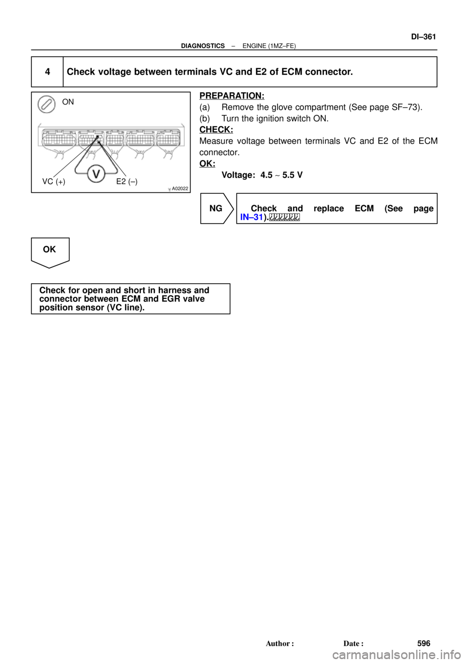
4 Check voltage between terminals VC and E2 of ECM connector.
PREPARATION:
(a) Remove the glove compartment (See page SF±73).
(b) Turn the ignition switch ON.
CHECK:
Measure voltage between terminals VC and E2 of the ECM
connector.
OK:
Voltage: 4.5 ~ 5.5 V
NG Check and replace ECM (See page
IN±31).
OK
Check for open and short in harness and
connector between ECM and EGR valve
position sensor (VC line).
Page 2784 of 4770

DI±364
± DIAGNOSTICSENGINE (1MZ±FE)
599 Author�: Date�:
INSPECTION PROCEDURE
HINT:
Read freeze frame data using TOYOTA hand±held test")
A02037
ON
ON
Brake Pedal
DepressedBrake Pedal
Released
STP (+)
DI±364
± DIAGNOSTICSENGINE (1MZ±FE)
599 Author�: Date�:
INSPECTION PROCEDURE
HINT:
Read freeze frame data using TOYOTA hand±held tester or OBD II scan tool. Because freeze frame records
the engine conditions when the malfunction is detected, when troubleshooting it is useful for determining
whether the vehicle was running or stopped, the engine warmed up or not, the air±fuel ratio lean or rich, etc.
at the time of the malfunction.
1 Check operation of stop light.
CHECK:
Check if the stop lights go on and off normally when the brake pedal is operated and released.
NG Check and repair stop light circuit.
OK
2 Check STP signal.
When using TOYOTA hand±held tester:
PREPARATION:
(a) Connect the TOYOTA hand±held tester to the DLC3.
(b) Turn the ignition switch ON and push the TOYOTA hand±
held tester main switch ON.
CHECK:
Read the STP signal on the TOYOTA hand±held tester.
OK:
Brake pedal is depressed: STP ...... ON
Brake pedal is released: STP ...... OFF
When not using TOYOTA hand±held tester:
PREPARATION:
Turn the ignition switch ON.
CHECK:
Check voltage between terminal STP of the ECM connector
and body ground.
OK:
Brake pedalVoltage
Depressed7.5 ~ 14 V
ReleasedBelow 1.5 V
OK Check for intermittent problems
(See page DI±197).
NG
Page 2785 of 4770
± DIAGNOSTICSENGINE (1MZ±FE)
DI±365
600 Author�: Date�:
3 Check harness and connector between ECM and stop light switch
(See page IN±31).
NG Repair or replace harness or connector.
OK
Check and replace ECM (See page IN±31).
Page 2787 of 4770
A02038
LOCK
BATT (+)
S04162
Engine Room J/B
EFI Fuse
± DIAGNOSTICSENGINE (1MZ±FE)
DI±367
602 Author�: Date�:
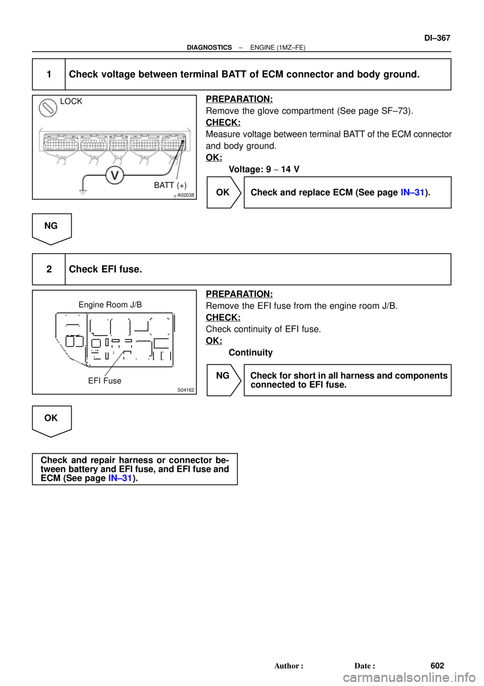
1 Check voltage between terminal BATT of ECM connector and body ground.
PREPARATION:
Remove the glove compartment (See page SF±73).
CHECK:
Measure voltage between terminal BATT of the ECM connector
and body ground.
OK:
Voltage: 9 ~ 14 V
OK Check and replace ECM (See page IN±31).
NG
2 Check EFI fuse.
PREPARATION:
Remove the EFI fuse from the engine room J/B.
CHECK:
Check continuity of EFI fuse.
OK:
Continuity
NG Check for short in all harness and components
connected to EFI fuse.
OK
Check and repair harness or connector be-
tween battery and EFI fuse, and EFI fuse and
ECM (See page IN±31).
Page 2790 of 4770
A02382
+B (+)
E1 (±)
A02951
IGSW (+)
DI±370
± DIAGNOSTICSENGINE (1MZ±FE)
605 Author�: Date�:
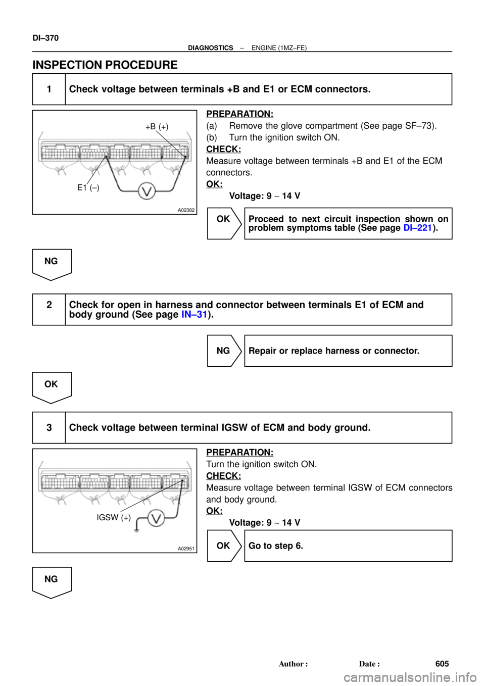
INSPECTION PROCEDURE
1 Check voltage between terminals +B and E1 or ECM connectors.
PREPARATION:
(a) Remove the glove compartment (See page SF±73).
(b) Turn the ignition switch ON.
CHECK:
Measure voltage between terminals +B and E1 of the ECM
connectors.
OK:
Voltage: 9 ~ 14 V
OK Proceed to next circuit inspection shown on
problem symptoms table (See page DI±221).
NG
2 Check for open in harness and connector between terminals E1 of ECM and
body ground (See page IN±31).
NG Repair or replace harness or connector.
OK
3 Check voltage between terminal IGSW of ECM and body ground.
PREPARATION:
Turn the ignition switch ON.
CHECK:
Measure voltage between terminal IGSW of ECM connectors
and body ground.
OK:
Voltage: 9 ~ 14 V
OK Go to step 6.
NG
Page 2791 of 4770
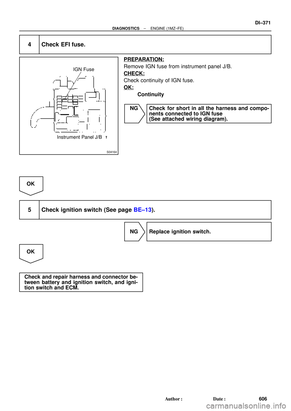
S04164
IGN Fuse
Instrument Panel J/B
± DIAGNOSTICSENGINE (1MZ±FE)
DI±371
606 Author�: Date�:
4 Check EFI fuse.
PREPARATION:
Remove IGN fuse from instrument panel J/B.
CHECK:
Check continuity of IGN fuse.
OK:
Continuity
NG Check for short in all the harness and compo-
nents connected to IGN fuse
(See attached wiring diagram).
OK
5 Check ignition switch (See page BE±13).
NG Replace ignition switch.
OK
Check and repair harness and connector be-
tween battery and ignition switch, and igni-
tion switch and ECM.