Page 2815 of 4770

Q00061
AT8562
AT3417
OK if hot
Add if hot
AT4252
0 ~ 1 mm (0 ~ 0.04 in.)
± DIAGNOSTICSAUTOMATIC TRANSAXLE (A140E)
DI±395
630 Author�: Date�:
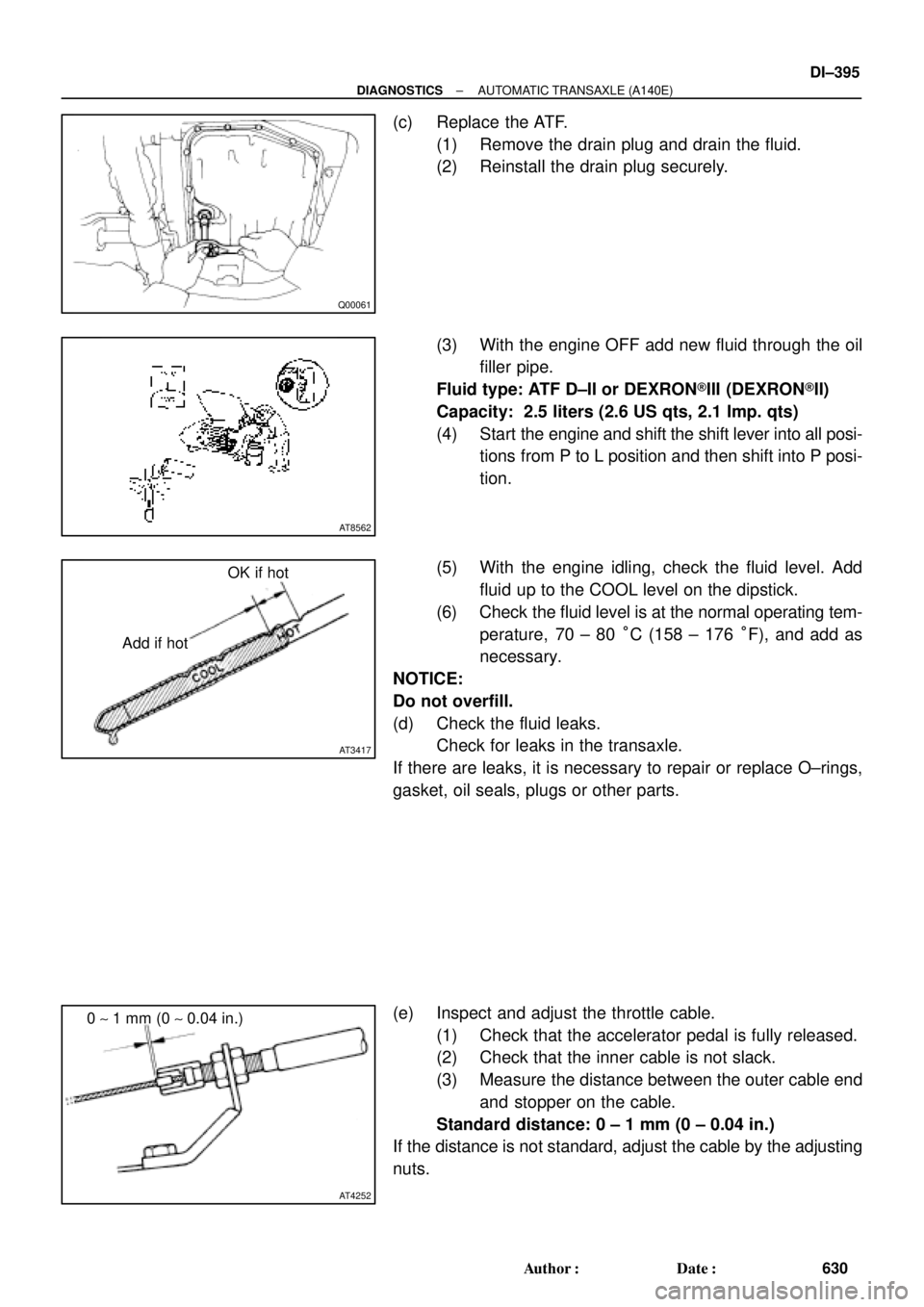
(c) Replace the ATF.
(1) Remove the drain plug and drain the fluid.
(2) Reinstall the drain plug securely.
(3) With the engine OFF add new fluid through the oil
filler pipe.
Fluid type: ATF D±II or DEXRON®III (DEXRON®II)
Capacity: 2.5 liters (2.6 US qts, 2.1 Imp. qts)
(4) Start the engine and shift the shift lever into all posi-
tions from P to L position and then shift into P posi-
tion.
(5) With the engine idling, check the fluid level. Add
fluid up to the COOL level on the dipstick.
(6) Check the fluid level is at the normal operating tem-
perature, 70 ± 80 °C (158 ± 176 °F), and add as
necessary.
NOTICE:
Do not overfill.
(d) Check the fluid leaks.
Check for leaks in the transaxle.
If there are leaks, it is necessary to repair or replace O±rings,
gasket, oil seals, plugs or other parts.
(e) Inspect and adjust the throttle cable.
(1) Check that the accelerator pedal is fully released.
(2) Check that the inner cable is not slack.
(3) Measure the distance between the outer cable end
and stopper on the cable.
Standard distance: 0 ± 1 mm (0 ± 0.04 in.)
If the distance is not standard, adjust the cable by the adjusting
nuts.
Page 2816 of 4770

Q00199
Q01561
P
R
N
AT4478
Neutral Basic line
Groove
DI±396
± DIAGNOSTICSAUTOMATIC TRANSAXLE (A140E)
631 Author�: Date�:
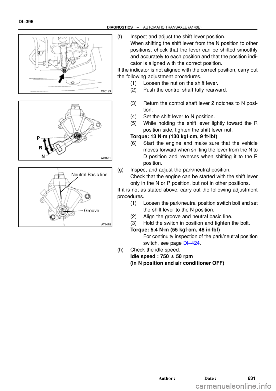
(f) Inspect and adjust the shift lever position.
When shifting the shift lever from the N position to other
positions, check that the lever can be shifted smoothly
and accurately to each position and that the position indi-
cator is aligned with the correct position.
If the indicator is not aligned with the correct position, carry out
the following adjustment procedures.
(1) Loosen the nut on the shift lever.
(2) Push the control shaft fully rearward.
(3) Return the control shaft lever 2 notches to N posi-
tion.
(4) Set the shift lever to N position.
(5) While holding the shift lever lightly toward the R
position side, tighten the shift lever nut.
Torque: 13 N´m (130 kgf´cm, 9 ft´lbf)
(6) Start the engine and make sure that the vehicle
moves forward when shifting the lever from the N to
D position and reverses when shifting it to the R
position.
(g) Inspect and adjust the park/neutral position.
Check that the engine can be started with the shift lever
only in the N or P position, but not in other positions.
If it is not as stated above, carry out the following adjustment
procedures.
(1) Loosen the park/neutral position switch bolt and set
the shift lever to the N position.
(2) Align the groove and neutral basic line.
(3) Hold the switch in position and tighten the bolt.
Torque: 5.4 N´m (55 kgf´cm, 48 in´lbf)
For continuity inspection of the park/neutral position
switch, see page DI±424.
(h) Check the idle speed.
Idle speed : 750 ± 50 rpm
(In N position and air conditioner OFF)
Page 2817 of 4770

± DIAGNOSTICSAUTOMATIC TRANSAXLE (A140E)
DI±397
632 Author�: Date�:
6. MECHANICAL SYSTEM TESTS
(a) Measure the stall speed.
The object of this test is to check the overall performance of the transaxle and engine by measuring
the stall speeds in the D and R positions.
NOTICE:
�Do the test at normal operating fluid temperature 50 ± 80 °C (122 ± 176 °F).
�Do not continuously run this test for longer than 5 seconds.
�To ensure safety, conduct this test in a wide, clear level area which provides good traction.
�The stall test should always be carried out in pairs. One technician should observe the condi-
tions of wheels or wheel stoppers outside the vehicle while the other is doing the test.
(1) Chock the 4 wheels.
(2) Connect an OBD II scan tool or TOYOTA hand±held tester to DLC3.
(3) Fully apply the parking brake.
(4) Keep your left foot depressing firmly on the brake pedal.
(5) Start the engine.
(6) Shift into the D position. Press all the way down on the accelerator pedal with your right foot.
Quickly read the stall speed at this time.
Stall speed: 2,450 ± 150 rpm
(7) Do the same test in R position.
Stall speed: 2,450 ± 150 rpm
Evaluation:
ProblemPossible cause
(a) Stall speed low in D and R positions
�Engine output may be insufficient
�Stator one±way clutch is operating properly
�HINT: If more than 600 rpm below the specified value, the torque
converter clutch could be faulty.
(b) Stall speed high in D position
�Line pressure too low
�Forward clutch slipping
�No.2 one±way clutch not operating properly
�O/D clutch slipping
(c) Stall speed high in R position
�Line pressure too low
�Direct clutch slipping
�1st & reverse brake slipping
�O/D clutch slipping
(d) Stall speed high in D and R positions
�Line pressure too low
�Improper fluid level
�O/D one±way clutch not operating properly
Page 2818 of 4770

DI±398
± DIAGNOSTICSAUTOMATIC TRANSAXLE (A140E)
633 Author�: Date�:
(b) Measure the time lag.
When the shift lever is shifted while the engine is idling, there will be a certain time lapse or lag before
the shock can be felt. This is used for checking the condition of the O/D direct clutch, forward clutch,
and 1st & reverse brake.
NOTICE:
�Do the test at normal operating fluid temperature 50 ± 80 °C (122 ± 176 °F).
�Be sure to allow 1 minute interval between tests.
�Take 3 measurements and take the average value.
(1) Connect an OBD II scan tool or TOYOTA hand±held tester to DLC3.
(2) Fully apply the parking brake.
(3) Start the engine and check idle speed.
Idle speed : 750 ± 50 rpm (In N position and air conditioner OFF)
(4) Shift the shift lever from N to D position. Using a stop watch, measure the time from when the
lever is shifted until the shock is felt.
Time lag: N " D Less than 1.2 seconds
(5) In the same manner, measure the time lag for N " R.
Time lag: N " R Less than 1.5 seconds
Evaluation (If N " D time or N " R time lag is longer than the specified):
ProblemPossible cause
N " D time lag is longer
�Line pressure too low
�Forward clutch worn
�O/D one±way clutch not operating
N " R time lag is longer
�Line pressure too low
�Direct clutch worn
�1st & reverse brake worn
�O/D one±way clutch not operating properly
Page 2819 of 4770

± DIAGNOSTICSAUTOMATIC TRANSAXLE (A140E)
DI±399
634 Author�: Date�:
7. HYDRAULIC TEST
Measure the line pressure.
NOTICE:
�Do the test at normal operation fluid temperature 50 ± 80 °C (122 ± 176 °F).
�The line pressure test should always be carried out in pairs. One technician should observe
the conditions of wheels or wheel stoppers outside the vehicle while the other is doing the test.
�Be careful to prevent SST's hose from interfering with the exhaust pipe.
(1) Warm up the ATF.
(2) Remove the test plug on the transaxle case front left side and connect SST.
(See page AX±17 for the location to connect SST)
SST 09992±00095 (09992±00231, 09992±00271)
(3) Fully apply the parking brake and chock the 4 wheels.
(4) Connect an OBD II scan tool or TOYOTA hand±held tester to DLC3.
(5) Start the engine and check idling speed.
(6) Keep your left foot pressing firmly on the brake pedal and shift into D position.
(7) Measure the line pressure when the engine is idling.
(8) Depress the accelerator pedal all the way down. Quickly read the highest line pressure when
engine speed reaches stall speed.
(9) In the same manner, do the test in R position.
Specified line pressure:
ConditionD position kPa (kgf/cm2, psi)R position kPa (kgf/cm2, psi)
Idling362 ± 422 (3.7 ± 4.3, 53 ± 61)618 ± 794 (6.3 ± 8.1, 90 ± 115)
Stall735 ± 862 (7.5 ± 8.8, 107 ± 125)1,373 ± 1,608 (14.0 ± 16.4, 199 ± 233)
If the measured pressure is not up to the specified value, recheck the throttle cable adjustment and retest.
Evaluation
ProblemPossible cause
If the measured values at all positions are higher
�Throttle cable out of adjustment
�Throttle valve defective
�Regulator valve defective
If the measured values at all positions are lower
�Throttle cable out of adjustment
�Throttle valve defective
�Regulator valve defective
�Oil pump defective
�O/D direct clutch defective
If pressure is low in the D position only�D position circuit fluid leakage
�Forward clutch defective
If pressure is low in the R position only
�R position circuit fluid leakage
�Direct clutch defective
�1st & reverse brake defective
Page 2825 of 4770

DI030±02
± DIAGNOSTICSAUTOMATIC TRANSAXLE (A140E)
DI±405
640 Author�: Date�:
PROBLEM SYMPTOMS TABLE
If a normal code is displayed during the DTC check but the trouble still occurs, check the circuits for each
symptom in the order given in the charts on the following pages and proceed to the page given for trouble-
shooting.
The Matrix Chart is divided into 3 chapters.
Chapter 1: Electronic Circuit Matrix Chart
Chapter 2: On±vehicle Repair Matrix Chart
Chapter 3: Off±vehicle repair Matrix Chart
�If the instruction ºProceed to next circuit inspection shown on matrix chartº is given in the flow
chart for each circuit, proceed to the circuit with the next highest number in the table to continue
the check.
�If the trouble still occurs even though there are no abnormalities in any of the other circuits, then
check and replace the ECM.
1. Chapter 1: Electronic Circuit Matrix Chart
SymptomSuspect AreaSee page
No up±shift
(A particular gear, from 1st to 3rd gear, is not up±shifted)1. ECMIN±31
No up±shift (3rd " O/D)
1. O/D main switch & O/D OFF indicator light circuit
2. O/D cancel signal circuit
3. ECMDI±431
DI±428
IN±31
No down±shift (O/D " 3rd)1. ECMIN±31
No down±shift
(A particular gear, from 3rd to 1st gear, is not down±shifted)1. ECMIN±31
No lock±up or No lock±up off1. Stop light switch circuit
2. ECMDI±423
IN±31
Shift point too high or too low1. ECMIN±31
Up±shift to O/D from 3rd while O/D main switch is OFF1. O/D main switch & O/D OFF indicator light circuit
2. ECMDI±431
IN±31
Up±shift to O/D from 3rd while engine is cold1. ECMIN±31
Poor acceleration1. ECMIN±31
No kick±down1. ECMIN±31
Engine stalls when starting off or stopping1. ECMIN±31
Page 2829 of 4770

A03021D02238
SPD
SPD
ON
(±) w/ Engine Immobiliser System
w/o Engine Immobiliser System(+)
(±)
(+)
AT7809
4.5 ~ 5.5 V
0
Turn the wheel
± DIAGNOSTICSAUTOMATIC TRANSAXLE (A140E)
DI±409
644 Author�: Date�:
INSPECTION PROCEDURE
1 Check operation of speedometer.
CHECK:
Drive the vehicle and check if the operation of the speedmeter in the combination meter is normal.
HINT:
The vehicle speed sensor is operating normally if the speedometer display is normal.
NG Check speedometer circuit. See combination
meter troubleshooting (See page BE±47).
OK
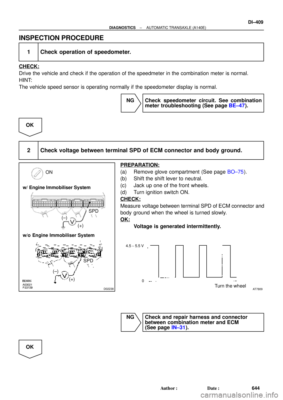
2 Check voltage between terminal SPD of ECM connector and body ground.
PREPARATION:
(a) Remove glove compartment (See page BO±75).
(b) Shift the shift lever to neutral.
(c) Jack up one of the front wheels.
(d) Turn ignition switch ON.
CHECK:
Measure voltage between terminal SPD of ECM connector and
body ground when the wheel is turned slowly.
OK:
Voltage is generated intermittently.
NG Check and repair harness and connector
between combination meter and ECM
(See page IN±31).
OK
Page 2834 of 4770
D01807
W3
E4 Transaxle
Shift Solenoid
Valve No.1
Shift Solenoid
Valve No.2
*2: w/o Engine
Immobiliser SystemE4 B1V7
21
*2
E9S1
*1: w/ Engine
Immobiliser System
A L ± B
*18
6
*2*1
E9
E9E9 L ± B J25
Junction
Connector
AAS2B+
B+
Cruise Control ECUECM
D00102 Q10102D00990
w/ Engine Immobiliser System
w/o Engine Immobiliser SystemS2
S1
S1
S2
DI±414
± DIAGNOSTICSAUTOMATIC TRANSAXLE (A140E)
649 Author�: Date�:
WIRING DIAGRAM
INSPECTION PROCEDURE
1 Measure resistance between terminal S1 or S2 of ECM and body ground.
PREPARATION:
Disconnect the connector from ECM.
CHECK:
Measure resistance between terminal S1 or S2 of ECM and
body ground.
OK:
Resistance: 11 ~ 15 W
OK Check and replace the ECM.
NG