Page 2877 of 4770
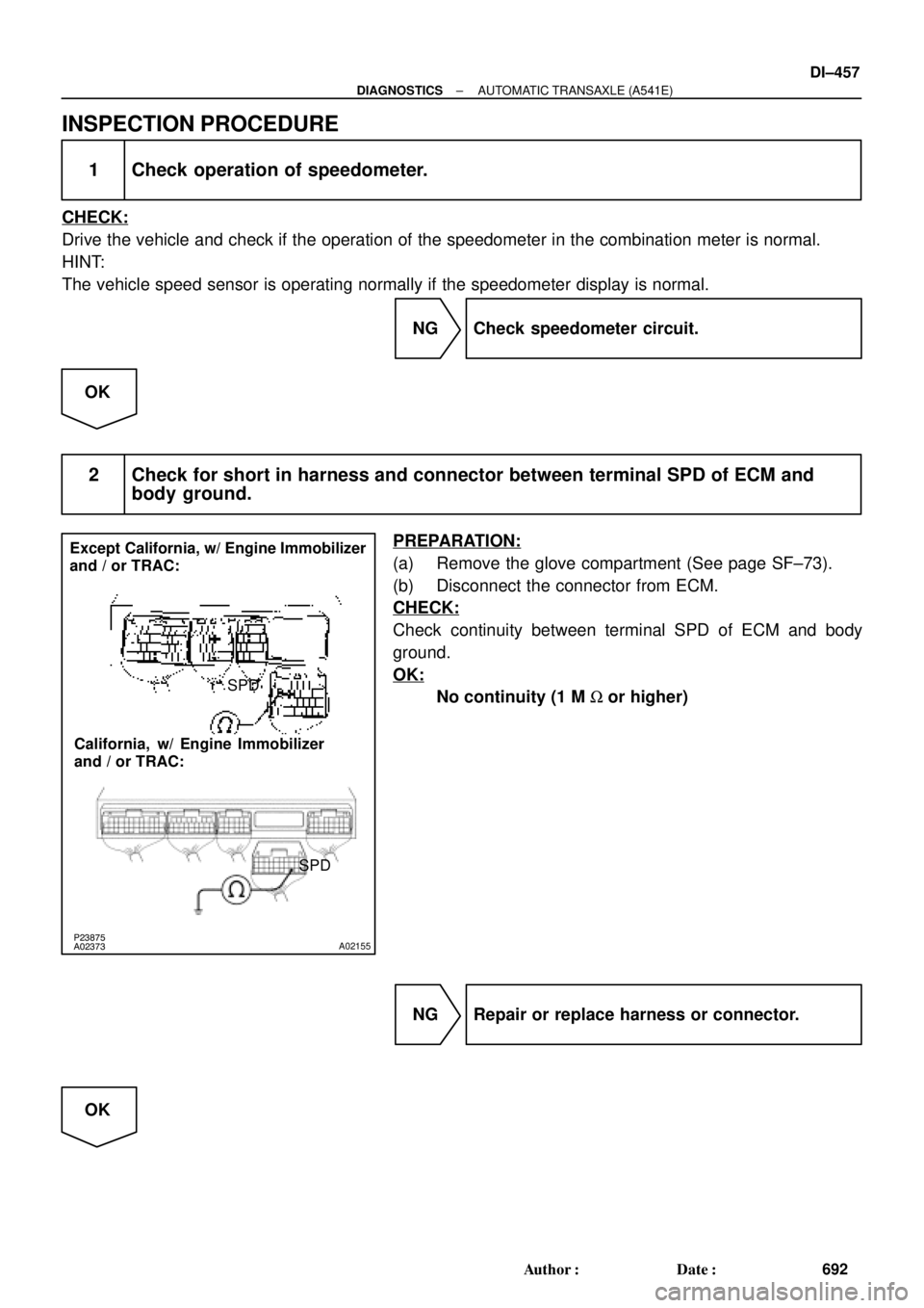
P23875
A02373A02155
Except California, w/ Engine Immobilizer
and / or TRAC:
California, w/ Engine Immobilizer
and / or TRAC:SPD
SPD
± DIAGNOSTICSAUTOMATIC TRANSAXLE (A541E)
DI±457
692 Author�: Date�:
INSPECTION PROCEDURE
1 Check operation of speedometer.
CHECK:
Drive the vehicle and check if the operation of the speedometer in the combination meter is normal.
HINT:
The vehicle speed sensor is operating normally if the speedometer display is normal.
NG Check speedometer circuit.
OK
2 Check for short in harness and connector between terminal SPD of ECM and
body ground.
PREPARATION:
(a) Remove the glove compartment (See page SF±73).
(b) Disconnect the connector from ECM.
CHECK:
Check continuity between terminal SPD of ECM and body
ground.
OK:
No continuity (1 M W or higher)
NG Repair or replace harness or connector.
OK
Page 2878 of 4770
BE6653P23876D01908D02281
ON
SPD
(±)(+)
(±)
(+)
SPD Except California, w/ Engine
Immobilizer and / or TRAC:
California, w/ Engine Immobilizer
and / or TRAC:
DI±458
± DIAGNOSTICSAUTOMATIC TRANSAXLE (A541E)
693 Author�: Date�:
3 Check voltage between terminal SPD of ECM connector and body ground.
PREPARATION:
Turn ignition switch ON.
CHECK:
Measure voltage between terminal SPD of ECM connector and
body ground.
OK:
Voltage: 9 ~ 14 V
NG Check for open in harness and connector be-
tween junction connector (J15) and ECM (See
page IN±31).
OK
4 Check for open in harness and connector between junction connector (J15) and
combination meter (See page IN±31).
NG Repair or replace harness or connector.
OK
Page 2883 of 4770
D01092
Transaxle
*1: Except California, w/ Engine Immobilizer and / or TRAC
*2: California, w/ Engine Immobilizer and / or TRACShift Solenoid
Valve No.1
W3
6 E3
L±B BV
J/C J26
A*2 *1
Shift Solenoid
Valve No.2
E3A
AL±BE11
E10 7
11
817
E10
E11 *2 *1ECM
B+
S1
S2B+
Cruise Control ECU
Q07642D00833D01909
California, w/ Engine Immobilizer
and / or TRAC:S1
S2
S1
S2
Except California, w/ Engine Immobilizer
and / or TRAC:
± DIAGNOSTICSAUTOMATIC TRANSAXLE (A541E)
DI±463
698 Author�: Date�:
WIRING DIAGRAM
INSPECTION PROCEDURE
1 Measure resistance between terminal S1 or S2 of ECM and body ground.
PREPARATION:
Disconnect the connector from ECM.
CHECK:
Measure resistance between terminal S1 or S2 of ECM and
body ground.
OK:
Resistance: 11 ~ 15 W
Page 2884 of 4770
D00832Q02283
Q07935
D01910
S1 S2
S1 S2S1
S2 S1 S2 California, w/ Engine Immobilizer
and / or TRAC: Except California, w/ Engine Immobilizer
and / or TRAC:
DI±464
± DIAGNOSTICSAUTOMATIC TRANSAXLE (A541E)
699 Author�: Date�:
OK Check and replace the ECM.
NG
2 Check harness and connector between ECM and automatic transaxle solenoid
connector.
PREPARATION:
Disconnect the solenoid connector from the automatic trans-
axle.
CHECK:
Check the harness and connector between terminal S1 or S2
of ECM and terminal S1 or S2 of solenoid connector.
OK:
There is no open and no short circuit.
NG Repair or replace the harness or connector.
OK
Page 2889 of 4770
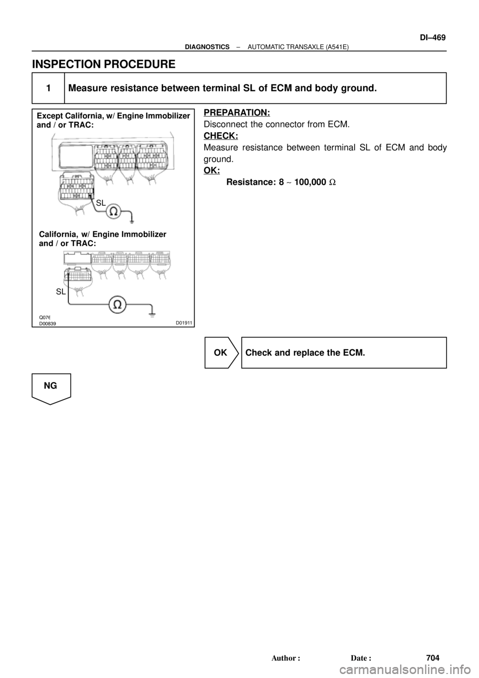
Q07648D00839D01911
Except California, w/ Engine Immobilizer
and / or TRAC:
California, w/ Engine Immobilizer
and / or TRAC:SL
SL
± DIAGNOSTICSAUTOMATIC TRANSAXLE (A541E)
DI±469
704 Author�: Date�:
INSPECTION PROCEDURE
1 Measure resistance between terminal SL of ECM and body ground.
PREPARATION:
Disconnect the connector from ECM.
CHECK:
Measure resistance between terminal SL of ECM and body
ground.
OK:
Resistance: 8 ~ 100,000 W
OK Check and replace the ECM.
NG
Page 2890 of 4770
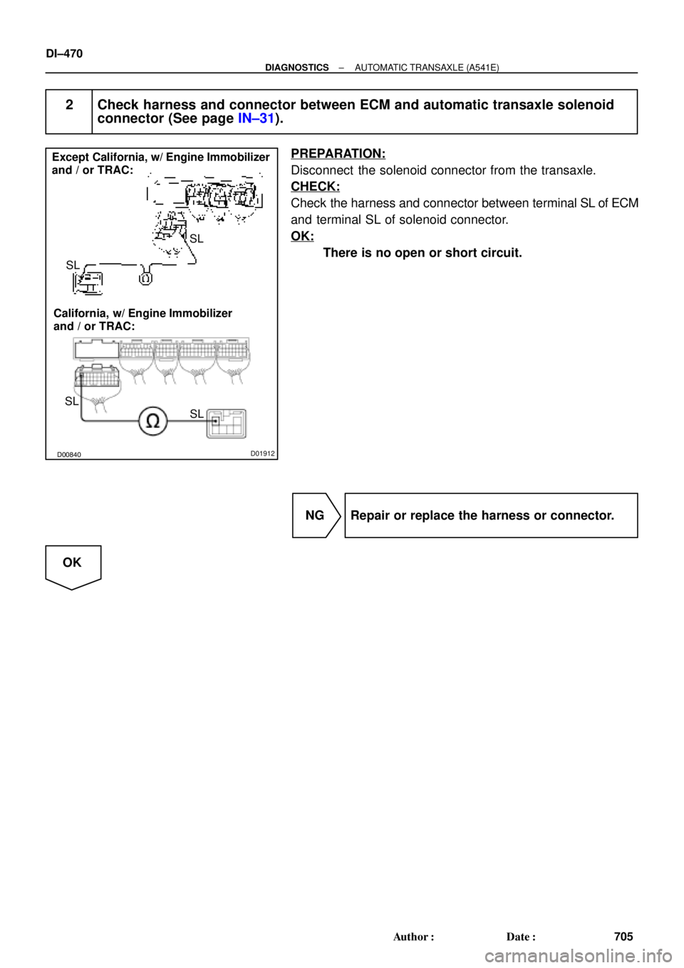
Q07938D00840D01912
SL
SL
SL
SL Except California, w/ Engine Immobilizer
and / or TRAC:
California, w/ Engine Immobilizer
and / or TRAC:
DI±470
± DIAGNOSTICSAUTOMATIC TRANSAXLE (A541E)
705 Author�: Date�:
2 Check harness and connector between ECM and automatic transaxle solenoid
connector (See page IN±31).
PREPARATION:
Disconnect the solenoid connector from the transaxle.
CHECK:
Check the harness and connector between terminal SL of ECM
and terminal SL of solenoid connector.
OK:
There is no open or short circuit.
NG Repair or replace the harness or connector.
OK
Page 2894 of 4770
Q07936D00834D01913
NC2+NC2±
NC2+
NC2±
Except California, w/ Engine Immobilizer
and / or TRAC:
California, w/ Engine Immobilizer
and / or TRAC:
DI±474
± DIAGNOSTICSAUTOMATIC TRANSAXLE (A541E)
709 Author�: Date�:
INSPECTION PROCEDURE
1 Check resistance between terminals NC2+ and NC2± of ECM.
PREPARATION:
Disconnect the connector from ECM.
CHECK:
Check resistance between terminals NC2+ and NC2± of ECM.
OK:
Resistance: 560 ~ 680 W
OK Check and replace the ECM.
NG
Page 2897 of 4770
D01095
Shift Solenoid
Valve SLN 1
4
B±YW±L3
2
SLN
±
SLN+
ECM
*1: Except California, w/ Engine Immobilizer and / or TRAC
*2: California, w/ Engine Immobilizer and / or TRAC*2 *1
E11
E3E10
E9 E3*2 *1
1920
R
L
E11
D00050
2
1
21
± DIAGNOSTICSAUTOMATIC TRANSAXLE (A541E)
DI±477
712 Author�: Date�:
WIRING DIAGRAM
INSPECTION PROCEDURE
1 Check shift solenoid valve SLN.
PREPARATION:
Disconnect the shift solenoid valve SLN connector.
CHECK:
(a) Measure resistance between terminals 1 and 2 of sole-
noid connector.
(b) Connect positive � lead with an 8 ~10 W bulb to terminal
1 of solenoid connector and negative ��lead to terminal
2, then check the movement of the valve.
OK:
(a) Resistance: 5.1 ~ 5.5 W
(b)
When battery positive voltage is applied.Valve move in direction in illustration.
(on the left)
When battery positive voltage is cut off.Valve move in direction in illustration.
(on the right)
(+)
(±)
(+)
SPD Except California, w/ Engine
Immobilizer and / or TRAC:
California, w/ Engine Immobilizer
and / or TRAC:
DI±458
± DIAGNOSTICSAUTOMATIC TRANSAXL")


709")
