Page 2996 of 4770

72 67
ON
OFF
0.5 sec. 0.5 sec. 0.5 sec. 0.5 sec.1.5 sec.
2.5 sec.4 sec.
Repeat DI±576
± DIAGNOSTI")
F02201
DLC1
TsTc E
1
BR3904
0.13 sec. 0.13 sec.
ON
OFF
BR3893
Malfunction Code (Example Code 72, 76)
72 67
ON
OFF
0.5 sec. 0.5 sec. 0.5 sec. 0.5 sec.1.5 sec.
2.5 sec.4 sec.
Repeat DI±576
± DIAGNOSTICSABS & TRACTION CONTROL SYSTEM
811 Author�: Date�:
2. SPEED SENSOR SIGNAL
(a) Check the speed sensor signal.
(1) Turn the ignition switch OFF.
(2) Using SST, connect terminals Ts and E
1 of DLC1.
SST 09843 ± 18020
(3) Start the engine.
(4) Check that the ABS warning light blinks.
HINT:
If the ABS warning light does not blink, inspect the ABS warning
light circuit (See page DI±612).
(5) Drive vehicle straight forward.
HINT:
Drive vehicle faster than 45 km/h (28 mph) for several seconds.
(6) Stop the vehicle.
(7) Using SST, connect terminals Tc and E
1 of DLC1.
SST 09843 ± 18020
(8) Read the number of blinks of the ABS warning light.
HINT:
�See the list of DTC shown on the next page.
�If 2 or more malfunctions are indicated at the same time,
the lowest numbered code will be displayed 1st.
�If every sensor is normal, a normal code is output (A cycle
of 0.25 sec. ON and 0.25 sec. OFF is repeated).
(9) After doing the check, disconnect the SST from ter-
minals Ts and E
1, Tc and E1 of DLC1, and turn igni-
tion switch OFF.
SST 09843 ± 18020
Page 3004 of 4770

DI04J±04
F03951
ABS & TRAC Solenoid Relay
Battery
MAINB±G1F4 ALT1F5 B±G
FL
BlockW±B
EA 3 ABS
12
3 Engine Room R/B No. 3
1
2
336
4
53
3
3
W±L
A8
4ABS & TRAC
Actuator
ABS & TRAC
ECU
5
A8R
A1510
AST GR
GR±RABS & TRAC
ECU
11
A15
1
A15SR
R+
DLC1 DI±584
± DIAGNOSTICSABS & TRACTION CONTROL SYSTEM
819 Author�: Date�:
CIRCUIT INSPECTION
DTC 11, 12 ABS & TRAC Solenoid Relay Circuit
CIRCUIT DESCRIPTION
This relay supplies power to each ABS & TRAC solenoid. After the ignition switch is turned ON, if the initial
check is OK, the relay goes on.
DTC No.DTC Detecting ConditionTrouble Area
11
Condition 1. to 3. are detected:
1. Malfunction of solenoid relay monitor
2. Battery voltage will not exceed more than 17.0 V within
2.16 sec.
3. Battery voltage will not become less than 9.5 V within
2.16 sec., or after the solenoid relay is ON and AST
voltage of ECU terminal does not become 8.0 V or more.
�ABS & TRAC solenoid relay
�ABS & TRAC solenoid relay circuit
�ECU
12
Solenoid relay is OFF in the midst of premain routine, and
AST voltage of ECU terminal is 8.0 V or more, which con-
tinues for 2.04 sec. or more.
Fail safe function:
If any trouble occurs in the ABS & TRAC solenoid relay circuit, the ECU cuts off current to the ABS & TRAC
solenoid relay and prohibits ABS control and TRAC control.
WIRING DIAGRAM
Page 3005 of 4770
(±)
(+)(±)
(+)(±)(+)(±)
123
456
Engine Room R/B No. 3
F00055
ABS & TRAC
Solenoid
Relay
A15
AST
4
5
ABS & TRAC
Actuator
ECU
ABS & TRAC
Solenoid
Relay
A15
AST
4
5
ABS & TRAC
Actuator
ECU
A")
F00182
(+)(±)
(+)(±)
(+)(±)(+)(±)
123
456
Engine Room R/B No. 3
F00055
ABS & TRAC
Solenoid
Relay
A15
AST
4
5
ABS & TRAC
Actuator
ECU
ABS & TRAC
Solenoid
Relay
A15
AST
4
5
ABS & TRAC
Actuator
ECU
ABS & TRAC
Solenoid
Relay
A15
AST
4
5
ABS & TRAC
Actuator
ECU
ABS & TRAC
Solenoid
Relay3
A8
A8
A15
AST
4
5
ABS & TRAC
Actuator
ECUEngine Room R/B No. 3
± DIAGNOSTICSABS & TRACTION CONTROL SYSTEM
DI±585
820 Author�: Date�:
INSPECTION PROCEDURE
1 Check voltage between terminals 1 and 2 of Engine Room R/B No. 3 (for ABS &
TRAC solenoid relay).
PREPARATION:
Remove ABS & TRAC solenoid relay from Engine Room R/B
No. 3.
CHECK:
Measure the voltage between terminals 1 and 2 of Engine
Room R/B No. 3 (for ABS & TRAC solenoid relay).
OK:
Voltage: 10 ± 14 V
NG Check and repair harness or connector.
OK
2 Check continuity between terminal 3 of ABS & TRAC solenoid relay and terminal
AST of ABS & TRAC ECU.
CHECK:
Check continuity between terminal 3 of Engine Room R/B No.
3 (for ABS solenoid relay) and terminal AST of ABS & TRAC
ECU.
OK:
Continuity
HINT:
There is a resistance of 4 ~ 6 W between terminals A8 ± 4 and
A8 ± 5 of ABS actuator.
NG Repair or replace harness or ABS & TRAC
actuator.
OK
Page 3008 of 4770
 (±)
Engine Room
R/B No. 31
2
34 (+) (±)
Engine Room
R/B No. 31
2
34 (+) (±)
Engine Room
R/B No. 31
2
34 (+) (±)
Engine Room
R/B No. 3
F00056
ABS & TRAC
Motor
Relay
M2
A15
MT")
F00049
1
2
34 (+) (±)
Engine Room
R/B No. 31
2
34 (+) (±)
Engine Room
R/B No. 31
2
34 (+) (±)
Engine Room
R/B No. 31
2
34 (+) (±)
Engine Room
R/B No. 3
F00056
ABS & TRAC
Motor
Relay
M2
A15
MT
32
2
3
ABS & TRAC
Actuator
ECU
ABS & TRAC
Motor
Relay
M2
A15
MT
32
2
3
ABS & TRAC
Actuator
ECU
ABS & TRAC
Motor
Relay
M2
A15
MT
32
2
3
ABS & TRAC
Actuator
ECU
A8
ABS & TRAC
Motor
Relay
A8 M2
A15
MT
32
2
3
ABS & TRAC
Actuator
ECUEngine Room R/B
No. 3
DI±588
± DIAGNOSTICSABS & TRACTION CONTROL SYSTEM
823 Author�: Date�:
INSPECTION PROCEDURE
1 Check voltage between terminal 1 of Engine Room R/B No. 3 (for ABS & TRAC
motor relay) and body ground.
PREPARATION:
Remove ABS & TRAC motor relay from Engine Room R/B No.
3.
CHECK:
Measure voltage between terminal 1 of Engine Room R/B No.
3 (for ABS & TRAC motor relay) and body ground.
OK:
Voltage: 10 ± 14 V
NG Check and repair harness or connector.
OK
2 Check continuity between terminal 2 of ABS & TRAC motor relay and terminal
MT of ABS & TRAC ECU.
CHECK:
Check continuity between terminal 2 of Engine Room R/B No.
3 (for ABS & TRAC motor relay) and terminal MT of ABS &
TRAC ECU.
OK:
Continuity
HINT:
There is a resistance of 4 ~ 6 W between terminals A8 ± 2 and
A8 ± 3 of ABS & TRAC actuator.
NG Repair or replace harness or ABS & TRAC
actuator.
OK
Page 3011 of 4770

F03952
SRLH
10
SR
R+
SFLR
SRRR
SRC2
AST
10
SFLR
SRRR
SRC2
AST Battery
MAIN
B±G1F4
ALT
1 B±G
F5
FL
Block
W±B
EA 3
333 2 ABS
12 Engine Room R/B No. 3
ABS & TRAC
Solenoid
Relay
16 33
3
4
5
W±L DLC1GR
GR±R
4A8ABS & TRAC ECU
ABS & TRAC ActuatorA7
A7
A7
A7
A7
A7
A7
A7
A7
A7
A7
A7
A89
10
12
11
3
4
6
5
7
2
8
1
5R±B
G±Y
L±B
W±R
W±R
LG±B
W±L
R±G
B±R
B±Y
Y±R
Y±B
R11
A15
1A15
13
A15
25
A15
2A17
8A17
26
A15
12
A15
1A17
7A17
5A17
4A17
12
A17
6A17
A15
SFLH
SRRH
SFRR
SRLR
SRC1
SMC1
SMC2 SFRH
F00057
1 2 3
4 5 6
7
8 9 10 11 12
A7
4
1 2 3
4 5 6
7
8 9 10 11 12
A7
4
1 2 3
4 5 6
7
8 9 10 11 12
A7
4
1 2 3
4 5 6
7
8 9 10 11 12
A7
4
1 2 3
4 5 6
7
8 9 10 11 12
A7
41 2 3
4 5 6
7
8 9 10 11 12A8
A74
± DIAGNOSTICSABS & TRACTION CONTROL SYSTEM
DI±591
826 Author�: Date�:
WIRING DIAGRAM
INSPECTION PROCEDURE
1 Check ABS & TRAC actuator solenoid.
PREPARATION:
Disconnect the 2 connectors from ABS & TRAC actuator.
CHECK:
Check continuity between terminals A8 ± 4 and A7 ± 1, 2, 3, 4,
5, 6, 7, 8, 9, 10, 11, 12 of ABS & TRAC actuator connector.
OK:
Continuity
HINT:
Resistance of each solenoid coil is 1.2 W.
NG Replace ABS & TRAC actuator.
OK
Page 3019 of 4770
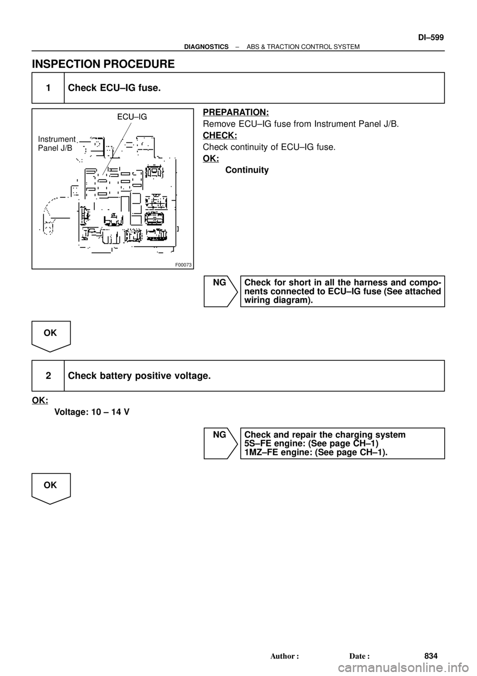
F00073
ECU±IGECU±IG
Instrument
Panel J/BECU±IG
± DIAGNOSTICSABS & TRACTION CONTROL SYSTEM
DI±599
834 Author�: Date�:
INSPECTION PROCEDURE
1 Check ECU±IG fuse.
PREPARATION:
Remove ECU±IG fuse from Instrument Panel J/B.
CHECK:
Check continuity of ECU±IG fuse.
OK:
Continuity
NG Check for short in all the harness and compo-
nents connected to ECU±IG fuse (See attached
wiring diagram).
OK
2 Check battery positive voltage.
OK:
Voltage: 10 ± 14 V
NG Check and repair the charging system
5S±FE engine: (See page CH±1)
1MZ±FE engine: (See page CH±1).
OK
Page 3021 of 4770

± DIAGNOSTICSABS & TRACTION CONTROL SYSTEM
DI±601
836 Author�: Date�:
DTC 43 ABS Control System Malfunction
CIRCUIT DESCRIPTION
DTC No.DTC Detecting ConditionTrouble Area
43
Detection of any conditions from 1. through 8.:
1. During TRAC is in non±operation and DTC of ABS is
output, but TRAC is not during initial lamp checking,
terminal WA of ECU is ON and engine speed is 500 rpm
or more , which continues for 1 sec. or more.
2. Solenoid relay circuit is open or short.
3. Motor relay circuit is open or short.
4. ABS solenoid circuit is open or short.
5. TRAC solenoid circuit is open or short.
6. Speed sensor is under malfunction condition.
7. IG power source is down or raised.
8. Pump motor is locked.
�ABS control system
INSPECTION PROCEDURE
1 Check the DTC for the ABS (See page DI±574).
*1 Repair ABS control system according to the
code output.
*2
Check for ECU connected to malfunction indicator lamp.
*1: Output NG code
*2: Malfunction indicator lamp remains ON.
DI04O±04
Page 3022 of 4770

F00062
ECMABS & TRAC ECU
NEONEO
E8
A16BR±W15 ECMABS & TRAC ECU
NEONEOA16BR±W15 ECMABS & TRAC ECU
NEONEOA16BR±W15 ECMABS & TRAC ECU
NEONEOA16BR±W15
ECMABS & TRAC ECU
NEONEO
A16BR±W15
16
DI±602
± DIAGNOSTICSABS & TRACTION CONTROL SYSTEM
837 Author�: Date�:
DTC 44 NE Signal Circuit
CIRCUIT DESCRIPTION
The ABS & TRAC ECU receives engine speed signals (NE signals) from the ECM.
DTC No.DTC Detecting ConditionTrouble Area
44
Condition 1. or 2. is detected:
1. TRAC is in operation and engine speed is 0 rpm contin-
ues for 2.4 sec. or more.
2. TRAC is in non±operation, sift lever is not in P or N posi-
tion, both the front right and left wheels' speed is 30
km/h (19 mph) or more, engine speed is 0 rpm and does
not have communication malfunction, and malfunction
information of engine system is OFF.
�NEO circuit
�ECM
�ECU
WIRING DIAGRAM
INSPECTION PROCEDURE
1 Check for open and short circuit in harness and connector between terminal
NEO of ABS & TRAC ECU and terminal NEO of ECM (See page IN±31).
NG Repair or replace harness or connector.
OK
DI04P±04