Page 3199 of 4770

(+)
SR+
(±)
SR±
ON
Engine Room Main
Wire Harness
u\"
H03354H06140H08258
Airbag
Sensor
Assembly Front Airbag
Sensor (RH)
(+)S")
H03354
H06141AB0119H08272
Airbag
Sensor
Assembly Front Airbag
Sensor (RH)
(+)
SR+
(±)
SR±
ON
Engine Room Main
Wire Harness
u"
H03354H06140H08258
Airbag
Sensor
Assembly Front Airbag
Sensor (RH)
(+)SR+
(±)SR± Engine Room Main
Wire Harness
± DIAGNOSTICSSUPPLEMENTAL RESTRAINT SYSTEM
DI±779
1014 Author�: Date�:
8 Check engine room main wire harness (to B+).
PREPARATION:
Disconnect the engine room main wire harness connector on
the airbag sensor assembly side.
CHECK:
(a) Turn ignition switch to ON.
(b) For the connector (on the RH front door wire harness
side) between the airbag sensor assembly and the en-
gine room main wire harness, measure the voltage be-
tween body ground and each of SR+ and SR±.
OK:
Voltage: Below 1 V
NG Repair or replace engine room main wire har-
ness.
OK
Repair or replace harness or connector between airbag sensor assembly and engine room main
wire harness.
9 Check engine room main wire harness (to ground).
PREPARATION:
Disconnect the engine room main wire harness connector on
the airbag sensor assembly side.
CHECK:
For the connector (on the engine room main wire harness side)
between the airbag sensor assembly and the engine room main
wire harness, measure the resistance between body ground
and each of SR+ and SR±.
OK:
Resistance: 1 MW or Higher
NG Repair or replace engine room main wire har-
ness.
OK
Repair or replace harness or connector between airbag sensor assembly and engine room main
wire harness.
Page 3200 of 4770
H03354H09519H09520
Airbag
Sensor
Assembly
Front Airbag
Sensor (RH)
(±) SR+SR±
Engine Room Main
Wire Harness
(+)
u "
DI±780
± DIAGNOSTICSSUPPLEMENTAL RESTRAINT SYSTEM
1015 Author�: Date�:
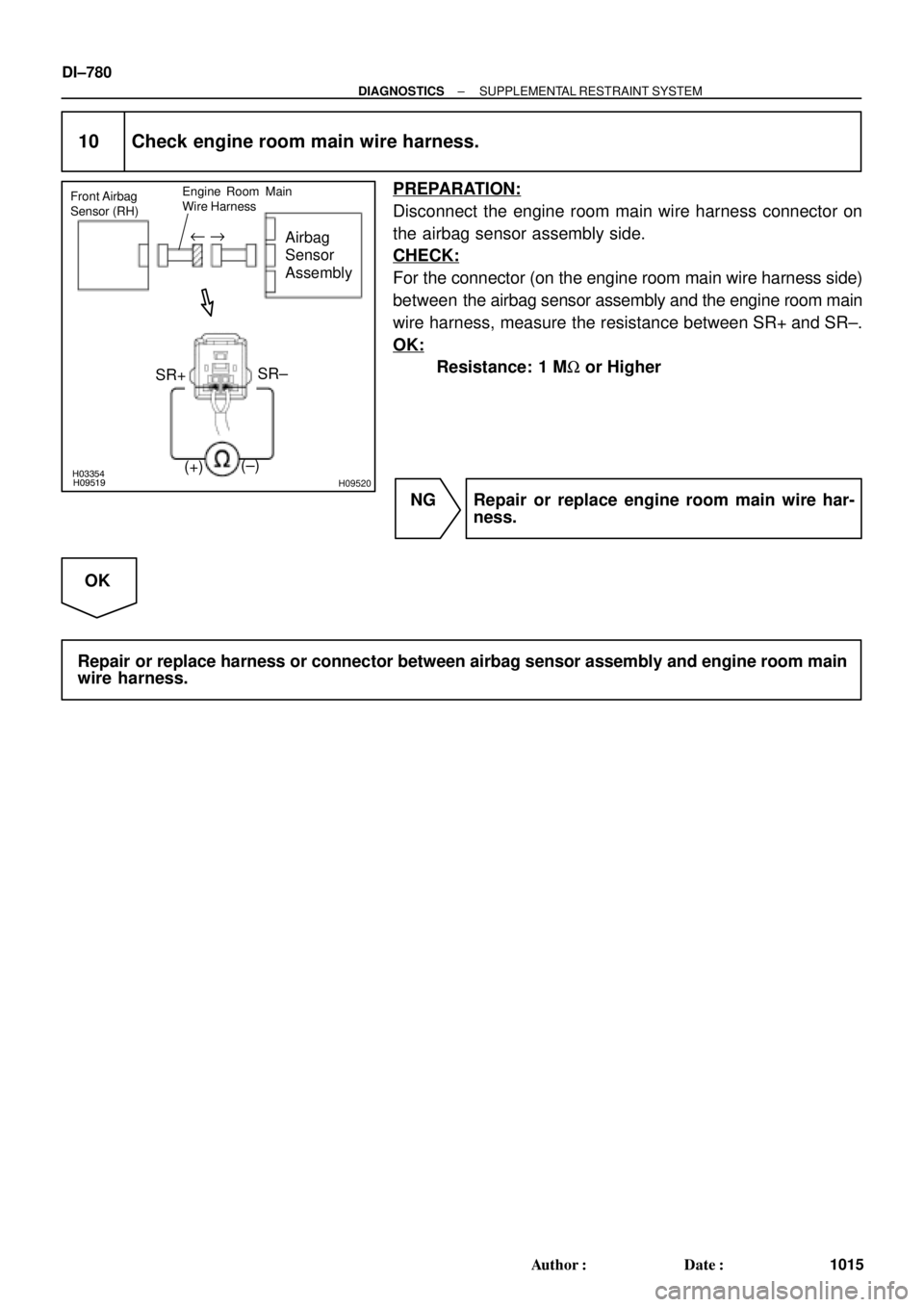
10 Check engine room main wire harness.
PREPARATION:
Disconnect the engine room main wire harness connector on
the airbag sensor assembly side.
CHECK:
For the connector (on the engine room main wire harness side)
between the airbag sensor assembly and the engine room main
wire harness, measure the resistance between SR+ and SR±.
OK:
Resistance: 1 MW or Higher
NG Repair or replace engine room main wire har-
ness.
OK
Repair or replace harness or connector between airbag sensor assembly and engine room main
wire harness.
Page 3201 of 4770
H03352H09519H09521H09522
Airbag
Sensor
Assembly Front Airbag
Sensor (RH)
(+) SR+
(±)SR±
Engine Room Main
Wire Harness
SR+
SR±
u "
± DIAGNOSTICSSUPPLEMENTAL RESTRAINT SYSTEM
DI±781
1016 Author�: Date�:
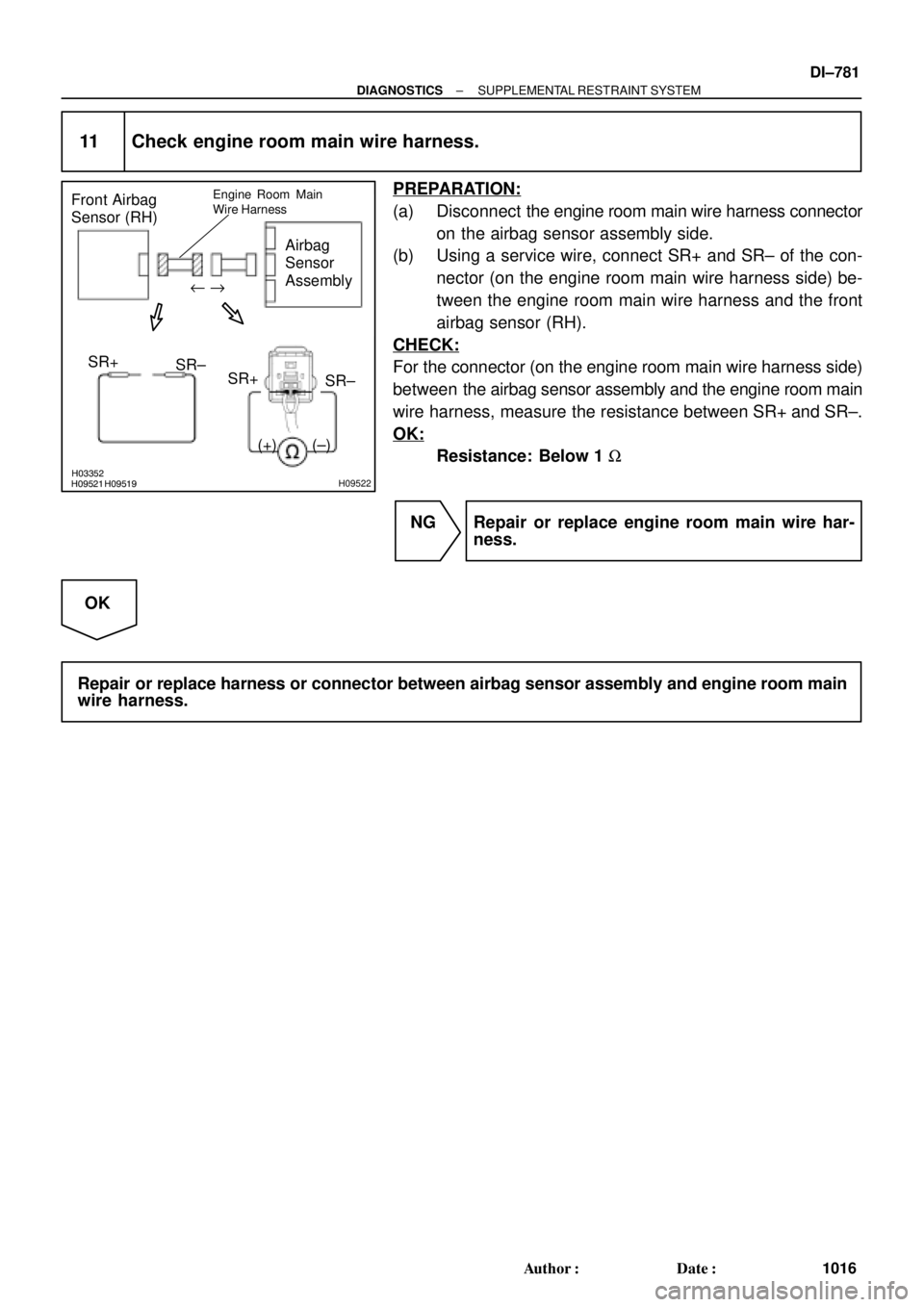
11 Check engine room main wire harness.
PREPARATION:
(a) Disconnect the engine room main wire harness connector
on the airbag sensor assembly side.
(b) Using a service wire, connect SR+ and SR± of the con-
nector (on the engine room main wire harness side) be-
tween the engine room main wire harness and the front
airbag sensor (RH).
CHECK:
For the connector (on the engine room main wire harness side)
between the airbag sensor assembly and the engine room main
wire harness, measure the resistance between SR+ and SR±.
OK:
Resistance: Below 1 W
NG Repair or replace engine room main wire har-
ness.
OK
Repair or replace harness or connector between airbag sensor assembly and engine room main
wire harness.
Page 3231 of 4770
N14677
AB0117
N14690
I00242
LOCK
E(±)
+B(+)
± DIAGNOSTICSWIRELESS DOOR LOCK CONTROL SYSTEM
DI±811
1046 Author�: Date�:
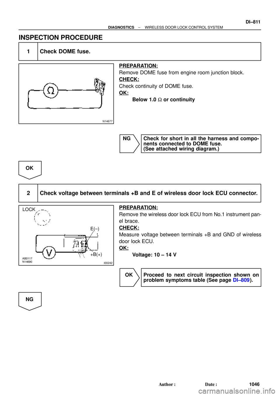
INSPECTION PROCEDURE
1 Check DOME fuse.
PREPARATION:
Remove DOME fuse from engine room junction block.
CHECK:
Check continuity of DOME fuse.
OK:
Below 1.0 W or continuity
NG Check for short in all the harness and compo-
nents connected to DOME fuse.
(See attached wiring diagram.)
OK
2 Check voltage between terminals +B and E of wireless door lock ECU connector.
PREPARATION:
Remove the wireless door lock ECU from No.1 instrument pan-
el brace.
CHECK:
Measure voltage between terminals +B and GND of wireless
door lock ECU.
OK:
Voltage: 10 ± 14 V
OK Proceed to next circuit inspection shown on
problem symptoms table (See page DI±809).
NG
Page 3247 of 4770

DI06N±05
THEFT DETERRENT SYSTEM Check Sheet
Inspector 's name:
Customer 's Name
Date of VehicleRegistration No.
Registration Year
Frame No.
Odometer Reading / /km
Mile
Weather Conditions
When Problem
Occurred Frequency Problem OccursWeather
Outdoor temperature
/ /
� Constant � Sometimes ( Times per day, month)
� Once only Brought in
� Theft deterrent system cannot be set.
� Indicator light does not flash when the theft deterrent system is set.
(It stays on or does not light at all.)
� Theft deterrent system
does not operate.� When unlocked using the
door lock knob.
� When the engine hood is
opened.
� System cannot be
canceled once set.� When door is unlocked using key or wireless door lock control system.
� When the key is inserted in the ignition key cylinder and turned to ACC or ON
position.
(However, only when the system has never operated)
� When the luggage compartment door is opened with the key.
� System cannot be
canceled during warning
operation.� When door is unlocked using key or wireless door lock control system.
� When the key is inserted in the ignition key cylinder and turned to ACC or ON
position.
� Warning operation starts when the system is set and the door or luggage compartment door is opened with
the key.
� Others.
Date Problem First Occurred
� Fine � Cloudy � Rainy � Snowy
� Various/Others
� Hot � Warm � Cool
� Cold (Approx. 5F ( 5C))
Problem Symptom
Malfunction
� Horns only
� Theft deterrent horn only
� Headlights only
� Taillights only
� Starter cut only
� Door lock operation only
± DIAGNOSTICSTHEFT DETERRENT SYSTEM
DI±827
1062 Author�: Date�:
CUSTOMER PROBLEM ANALYSIS CHECK
Page 3248 of 4770

DI1KU±02
DI±828
± DIAGNOSTICSTHEFT DETERRENT SYSTEM
1063 Author�: Date�:
PRE±CHECK
1. Active arming mode:
SETTING THE THEFT DETERRENT MODE
The system will be automatically set to the theft deterrent mode
about 30 seconds after the setting processes listed below are
performed.
Setting Processes: (do processes (1)�(4) in the order)
(1) Remove the ignition key from the key cylinder.
(2) Close all entry points (door, hood and luggage
compartment door).
(3) Use any one of the following methods to lock all the
doors depending on a given condition.
�Use the key to lock the driver or passenger
side door. (as a result, all the doors(including
the engine hood and luggage compartment
door) will be closed and locked), or
�Use the remote control to lock any door (as a
result, all the doors(including the engine
hood and luggage compartment door) will be
closed and locked), or
�If the front right or left door is unlocked when
both the rear doors are already locked, lock
and close the remaining unlocked door by
hand (as a result, all the doors(including the
engine hood and luggage compartment door)
will be closed and locked).
�Close all doors and lock with the engine hood
or luggage compartment door opened, and
close the engine hood or all the doors(includ-
ing the engine hood and luggage compart-
ment door).
(4) About 30 seconds after the above process (3), the
theft deterrent mode will automatically start.
HINT:
The closing/locking of all the entry points (doors, hood and lug-
gage) must remain unchanged for about 30 seconds, the sys-
tem will start the theft deterrent mode.
2. Passive arming mode:
SETTING THE THEFT DETERRENT MODE
The system will be automatically set to the theft deterrent mode
about 30 seconds after the setting processes listed below are
performed.
Setting Processes:
(1) Remove the ignition key from the key cylinder.
(2) Open and close any entry points (door, hood and
luggage compartment door).
Now, all the entry points are closed.
Page 3261 of 4770
I00268
I00269
I00275
E/G room J/B No.2:
Instrument panel J/B:DOME Fuse
DOOR Fuse
I01922E+B1
+B2
(+)
(±)
± DIAGNOSTICSTHEFT DETERRENT SYSTEM
DI±841
1076 Author�: Date�:
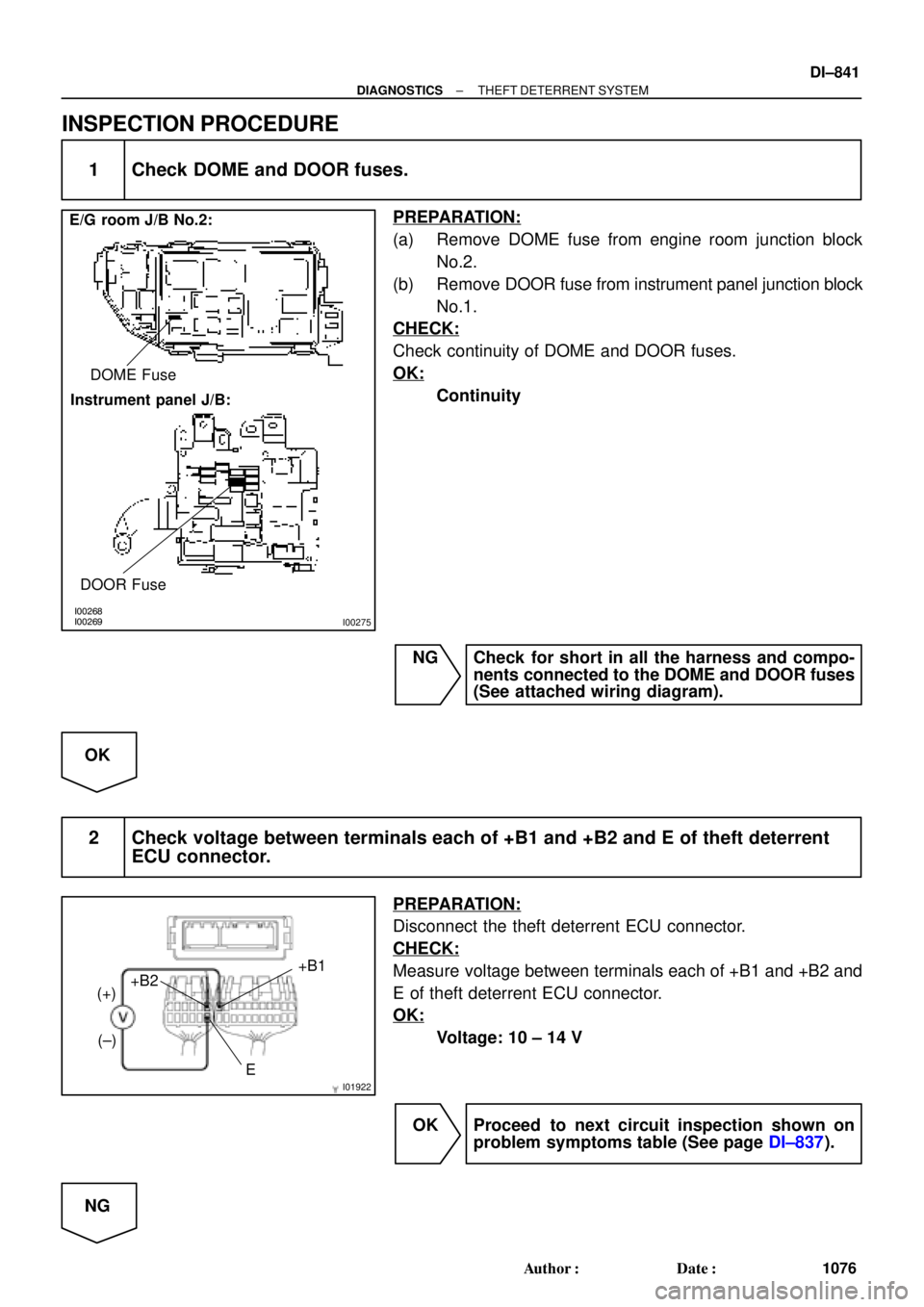
INSPECTION PROCEDURE
1 Check DOME and DOOR fuses.
PREPARATION:
(a) Remove DOME fuse from engine room junction block
No.2.
(b) Remove DOOR fuse from instrument panel junction block
No.1.
CHECK:
Check continuity of DOME and DOOR fuses.
OK:
Continuity
NG Check for short in all the harness and compo-
nents connected to the DOME and DOOR fuses
(See attached wiring diagram).
OK
2 Check voltage between terminals each of +B1 and +B2 and E of theft deterrent
ECU connector.
PREPARATION:
Disconnect the theft deterrent ECU connector.
CHECK:
Measure voltage between terminals each of +B1 and +B2 and
E of theft deterrent ECU connector.
OK:
Voltage: 10 ± 14 V
OK Proceed to next circuit inspection shown on
problem symptoms table (See page DI±837).
NG
Page 3287 of 4770
I00298
1 (+)
2 (±)
± DIAGNOSTICSTHEFT DETERRENT SYSTEM
DI±867
1102 Author�: Date�:
INSPECTION PROCEDURE
1 Check engine hood courtesy switch.
PREPARATION:
(a) Remove engine hood lock assembly.
(b) Disconnect engine hood courtesy switch connector.
CHECK:
Check continuity between terminals 1 and 2 when engine hood
lock is locked and unlocked.
OK:
Engine hood lockTester connectionSpecified condition
LOCK±No continuity
UNLOCK1 ± 2Continuity
NG Replace engine hood courtesy switch.
OK
2 Check harness and connector between theft deterrent ECU and switch, switch
and body ground (See page IN±31).
NG Repair or replace harness or connector.
OK
Check and replace theft deterrent ECU
(See page IN±31).