Page 2902 of 4770

BE3840D00052D00836D01914
Except California, w/ Engine Immobilizer
and / or TRAC:
California, w/ Engine Immobilizer
and / or TRAC:ON
L
NSW
2
R
2R
L
NSW
Position
P, N
R
D
2
LNSW±Body
groundR±Body
ground2±Body
groundL±Body
ground
0 V
0 V0 V0 V
0 V
0 V
0 V 0 V
0 V
0 V 0 V
0 V
0 V 9 ~ 14 V*
9 ~ 14 V
9 ~ 14 V
9 ~ 14 V9 ~ 14 V
9 ~ 14 V 9 ~ 14 V* DI±482
± DIAGNOSTICSAUTOMATIC TRANSAXLE (A541E)
717 Author�: Date�:
INSPECTION PROCEDURE
1 Read PNP, REVERSE, 2ND and LOW signals.
When using TOYOTA hand±held tester.
PREPARATION:
(a) Remove the DLC3 cover.
(b) Connect a TOYOTA hand±held tester to the DLC3.
(c) Turn the ignition switch ON and TOYOTA hand±held tes-
ter main switch ON.
CHECK:
Shift lever into the P, R, N, 2 and L positions, and read the PNP,
REVERSE, 2ND and LOW signals on the TOYOTA hand±held
tester.
OK:
Shift positionSignal
22ND OFF " ON
LLOW OFF " ON
RREVERSE OFF " ON
P, NNSW OFF " ON
When not using TOYOTA hand±held tester.
PREPARATION:
Turn the ignition switch ON.
CHECK:
Measure voltage between terminals NSW, 2, L and R of ECM
and body ground when the shift lever is shifted to the following
positions.
OK:
HINT:
*: The voltage will drop slightly due to lighting up of the back up
light.
Page 2905 of 4770
BE3840Q07659
D00053
D00835D01915
Except California, w/ Engine Immobilizer
and / or TRAC:
California, w/ Engine Immobilizer
and / or TRAC:OD1
OD1 ON
(+) (±) (±)
(+)
± DIAGNOSTICSAUTOMATIC TRANSAXLE (A541E)
DI±485
720 Author�: Date�:
INSPECTION PROCEDURE
1 Check voltage between terminal OD1 of ECM and body ground.
PREPARATION:
Turn the ignition switch ON.
CHECK:
Measure voltage between terminal OD1 of ECM and body
ground.
OK:
Voltage: 10 ~ 14 V
OK Proceed to next circuit inspection shown on
matrix chart (See page DI±453).
NG
Page 2909 of 4770
BE3840
D00837Q07662D01916
Except California, w/ Engine Immobilizer
and / or TRAC:
California, w/ Engine Immobilizer
and / or TRAC:
OD2 OD2
(+) (±) ON
(+) (±)
± DIAGNOSTICSAUTOMATIC TRANSAXLE (A541E)
DI±489
724 Author�: Date�:
When not using TOYOTA hand±held tester
PREPARATION:
Turn the ignition switch ON.
CHECK:
Check voltage between terminal OD2 of ECM and body ground.
OK:
O/D main switchVoltage
OFFBelow 1 V
ON10 ~ 14 V
NG Check and replace the ECM.
NG
4 Check harness and connector between O/D OFF indicator light and ECM
(See page IN±31).
NG Repair or replace the harness or connector.
OK
Check and replace the ECM.
Page 2915 of 4770

72 67
ON
OFF
0.5 sec. 0.5 sec. 0.5 sec. 0.5 sec.1.5 sec.
2.5 sec.4 sec.
Repeat
± DIAGNOSTICSANTI±L")
F02201
DLC1
TsTc E1
BR3904
0.13 sec. 0.13 sec.
ON
OFF
BR3893
Malfunction Code (Example Code 72, 76)
72 67
ON
OFF
0.5 sec. 0.5 sec. 0.5 sec. 0.5 sec.1.5 sec.
2.5 sec.4 sec.
Repeat
± DIAGNOSTICSANTI±LOCK BRAKE SYSTEM (DENSO Made)
DI±495
730 Author�: Date�:
2. SPEED SENSOR SIGNAL
(a) Check the speed sensor signal.
(1) Turn the ignition switch OFF.
(2) Using SST, connect terminals Ts and E
1 of DLC1.
SST 09843 ± 18020
(3) Start the engine.
(4) Check that the ABS warning light blinks.
HINT:
If the ABS warning light does not blink, inspect the ABS warning
light circuit (See page DI±529).
(5) Drive vehicle straight forward.
HINT:
Drive vehicle faster than 45 km/h (28 mph) for several seconds.
(6) Stop the vehicle.
(7) Using SST, connect terminals Tc and E
1 of DLC1.
SST 09843 ± 18020
(8) Read the number of blinks of the ABS warning light.
HINT:
�See the list of DTC shown on the next page.
�If every sensor is normal, a normal code is output (A cycle
of 0.25 sec. ON and 0.25 sec. OFF is repeated).
�If 2 or more malfunctions are indicated at the same time,
the lowest numbered code will be displayed 1st.
(9) After doing the check, disconnect the SST from ter-
minals Ts and E
1, Tc and E1 of DLC1, and turn igni-
tion switch OFF.
SST 09843 ± 18020
Page 2924 of 4770
 (±)
Engine Room
R/B No. 3
3
45 6 12 (+) (±)
Engine Room
R/B No. 3
3
45 6 12 (+) (±)
Engine Room
R/B No. 3
3
45 612 (+) (±)
Engine Room
R/B No. 3
3
45 6
F07153
3
4
ABS
Actuator
AB")
F00048
12 (+) (±)
Engine Room
R/B No. 3
3
45 6 12 (+) (±)
Engine Room
R/B No. 3
3
45 6 12 (+) (±)
Engine Room
R/B No. 3
3
45 612 (+) (±)
Engine Room
R/B No. 3
3
45 6
F07153
3
4
ABS
Actuator
ABS
Solenoid
Relay
A4
A18
ECUA5
1234
56781
5 2
6 3
7 4
8
SFRH
SFRR
SRLR
SRLH
SFLH
SFLR
SRRH
SRRR
DI±504
± DIAGNOSTICSANTI±LOCK BRAKE SYSTEM (DENSO Made)
739 Author�: Date�:
INSPECTION PROCEDURE
1 Check voltage between terminals 1 and 2 of Engine Room R/B No. 3 (for ABS so-
lenoid relay).
PREPARATION:
Remove ABS solenoid relay from Engine Room R/B No. 3.
CHECK:
Measure the voltage between terminals 1 and 2 of Engine
Room R/B No. 3 (for ABS solenoid relay).
OK:
Voltage: 10 ± 14 V
NG Check and repair harness or connector.
OK
2 Check continuity between terminal 3 of ABS solenoid relay and terminal SRLR,
SRLH, SRRR, SRRH, SFLR, SFLH, SFRR or SFRH of ABS ECU.
CHECK:
Check continuity between terminal 3 of Engine Room R/B No.3
(for ABS solenoid relay) and terminal SRLR, SRLH, SRRR,
SRRH, SFLR, SRLH, SFRR or SFRH of ABS ECU.
OK:
Continuity
HINT:
Resistance of each solenoid coil
SRLR, SRRR, SFLR, SFRR: 4.3 W
SRLH, SRRH, SFLH, SFRH: 8.8 W
NG Repair or replace harness or ABS actuator.
OK
Page 2929 of 4770
 (±)
Engine Room
R/B No. 3
2
34 1 (+) (±)
Engine Room
R/B No. 32
34 1 (+) (±)
Engine Room
R/B No. 32
34
1 (+) (±)
Engine Room
R/B No. 3
2
34
F07154
3 3
ECU ECU
ECU
ABS
Motor
Relay2")
F00049
1 (+) (±)
Engine Room
R/B No. 3
2
34 1 (+) (±)
Engine Room
R/B No. 32
34 1 (+) (±)
Engine Room
R/B No. 32
34
1 (+) (±)
Engine Room
R/B No. 3
2
34
F07154
3 3
ECU ECU
ECU
ABS
Motor
Relay2
A4
A4
A18
MT
2
2
ECU
ABS
Actuator
± DIAGNOSTICSANTI±LOCK BRAKE SYSTEM (DENSO Made)
DI±509
744 Author�: Date�:
INSPECTION PROCEDURE
1 Check voltage between terminal 1 of Engine Room R/B No. 3 (for ABS motor
relay) and body ground.
PREPARATION:
Remove ABS motor relay from Engine Room R/B No. 3.
CHECK:
Measure voltage between terminal 1 of Engine Room R/B No.
3 (for ABS motor relay) and body ground.
OK:
Voltage: 10 ± 14 V
NG Check and repair harness or connector.
OK
2 Check continuity between terminal 2 of ABS motor relay and terminal MT of ABS
ECU.
CHECK:
Check continuity between terminal 2 of Engine Room R/B No.3
(for ABS motor relay) and terminal MT of ABS ECU.
OK:
Continuity
HINT:
There is a resistance of 4 ~ 6 W between terminals A4 ± 2 and
A4 ± 3 of ABS actuator.
NG Repair or replace harness or ABS actuator.
OK
Page 2941 of 4770
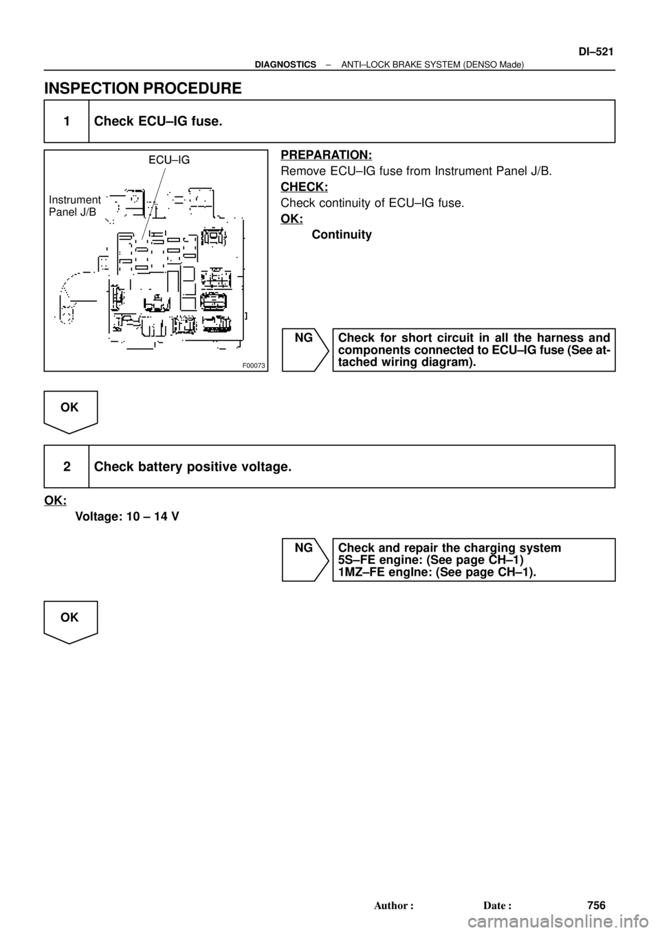
F00073
ECU±IGECU±IG
Instrument
Panel J/BECU±IG
± DIAGNOSTICSANTI±LOCK BRAKE SYSTEM (DENSO Made)
DI±521
756 Author�: Date�:
INSPECTION PROCEDURE
1 Check ECU±IG fuse.
PREPARATION:
Remove ECU±IG fuse from Instrument Panel J/B.
CHECK:
Check continuity of ECU±IG fuse.
OK:
Continuity
NG Check for short circuit in all the harness and
components connected to ECU±IG fuse (See at-
tached wiring diagram).
OK
2 Check battery positive voltage.
OK:
Voltage: 10 ± 14 V
NG Check and repair the charging system
5S±FE engine: (See page CH±1)
1MZ±FE engIne: (See page CH±1).
OK
Page 2948 of 4770
DI±528
± DIAGNOSTICSANTI±LOCK BRAKE SYSTEM (DENSO Made)
763 Author�: Date�:
4 Check battery positive voltage.
CHECK:
Check the battery positive voltage.
OK:
10 ± 14 V
NG Check and repair the charging system
5S±FE engine: (See page CH±1)
1MZ±FE engine: (See page CH±1).
OK
5 Check ABS warning light.
PREPARATION:
(a) Disconnect the connector from the ABS ECU.
(b) Turn the ignition switch ON.
CHECK:
Check the ABS warning light goes off.
OK Check and replace ABS ECU.
NG
Check for short circuit in harness and connector between ABS warning light, DLC1, DLC2, and
ABS ECU (See page IN±31).
 (±) (±)
(+)
± DIAGNOSTICSAUTOMATIC TRANSAXLE")
 (±) ON
(+) (±)
± DIAGNOSTICSAUTOMATIC TRANSAXLE (A541")