Page 3363 of 4770
EC03E±05
B01082B04812B06707
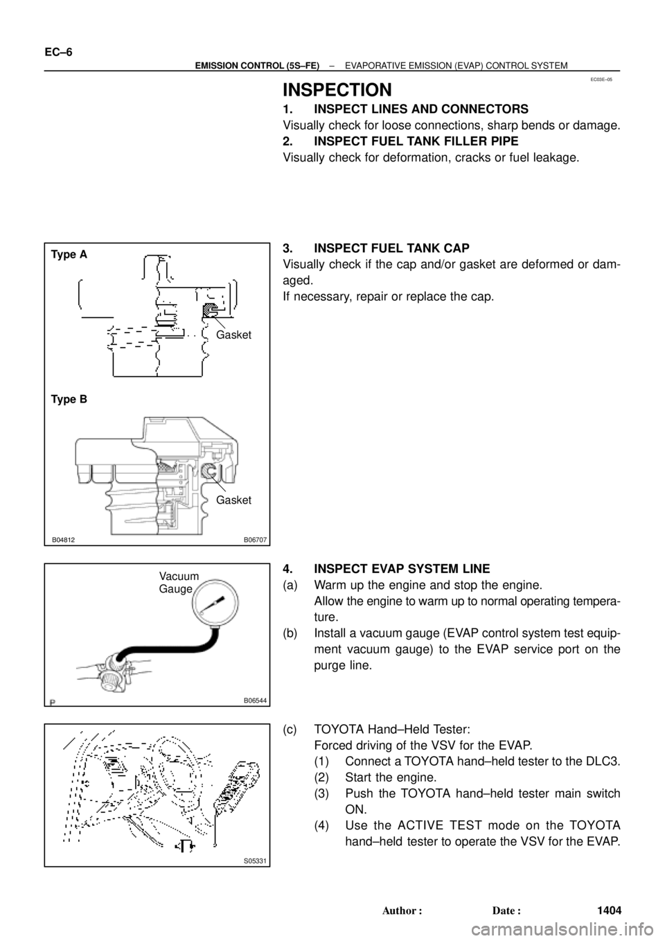
Type A
Type BGasket
Gasket
B06544
Vacuum
Gauge
S05331
EC±6
± EMISSION CONTROL (5S±FE)EVAPORATIVE EMISSION (EVAP) CONTROL SYSTEM
1404 Author�: Date�:
INSPECTION
1. INSPECT LINES AND CONNECTORS
Visually check for loose connections, sharp bends or damage.
2. INSPECT FUEL TANK FILLER PIPE
Visually check for deformation, cracks or fuel leakage.
3. INSPECT FUEL TANK CAP
Visually check if the cap and/or gasket are deformed or dam-
aged.
If necessary, repair or replace the cap.
4. INSPECT EVAP SYSTEM LINE
(a) Warm up the engine and stop the engine.
Allow the engine to warm up to normal operating tempera-
ture.
(b) Install a vacuum gauge (EVAP control system test equip-
ment vacuum gauge) to the EVAP service port on the
purge line.
(c) TOYOTA Hand±Held Tester:
Forced driving of the VSV for the EVAP.
(1) Connect a TOYOTA hand±held tester to the DLC3.
(2) Start the engine.
(3) Push the TOYOTA hand±held tester main switch
ON.
(4) Use the ACTIVE TEST mode on the TOYOTA
hand±held tester to operate the VSV for the EVAP.
Page 3364 of 4770
B06548Battery
B06545
B06543
Hose Clipper
Air Drain Hose
± EMISSION CONTROL (5S±FE)EVAPORATIVE EMISSION (EVAP) CONTROL SYSTEM
EC±7
1405 Author�: Date�:
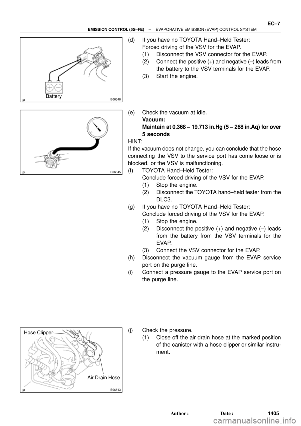
(d) If you have no TOYOTA Hand±Held Tester:
Forced driving of the VSV for the EVAP.
(1) Disconnect the VSV connector for the EVAP.
(2) Connect the positive (+) and negative (±) leads from
the battery to the VSV terminals for the EVAP.
(3) Start the engine.
(e) Check the vacuum at idle.
Vacuum:
Maintain at 0.368 ± 19.713 in.Hg (5 ± 268 in.Aq) for over
5 seconds
HINT:
If the vacuum does not change, you can conclude that the hose
connecting the VSV to the service port has come loose or is
blocked, or the VSV is malfunctioning.
(f) TOYOTA Hand±Held Tester:
Conclude forced driving of the VSV for the EVAP.
(1) Stop the engine.
(2) Disconnect the TOYOTA hand±held tester from the
DLC3.
(g) If you have no TOYOTA Hand±Held Tester:
Conclude forced driving of the VSV for the EVAP.
(1) Stop the engine.
(2) Disconnect the positive (+) and negative (±) leads
from the battery from the VSV terminals for the
EVAP.
(3) Connect the VSV connector for the EVAP.
(h) Disconnect the vacuum gauge from the EVAP service
port on the purge line.
(i) Connect a pressure gauge to the EVAP service port on
the purge line.
(j) Check the pressure.
(1) Close off the air drain hose at the marked position
of the canister with a hose clipper or similar instru-
ment.
Page 3369 of 4770
EC03G±04
S05568
Cap
Filter
B06540
Vacuum Gauge
3±Way Connector
A07370
SST
E1
TE1
B06541
HOTHigh Vacuum at 2,500 rpm
Port R
Disconnect
EC±12
± EMISSION CONTROL (5S±FE)EXHAUST GAS RECIRCULATION (EGR) SYSTEM
1410 Author�: Date�:
INSPECTION
1. INSPECT EGR SYSTEM
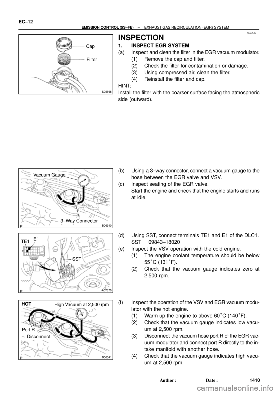
(a) Inspect and clean the filter in the EGR vacuum modulator.
(1) Remove the cap and filter.
(2) Check the filter for contamination or damage.
(3) Using compressed air, clean the filter.
(4) Reinstall the filter and cap.
HINT:
Install the filter with the coarser surface facing the atmospheric
side (outward).
(b) Using a 3±way connector, connect a vacuum gauge to the
hose between the EGR valve and VSV.
(c) Inspect seating of the EGR valve.
Start the engine and check that the engine starts and runs
at idle.
(d) Using SST, connect terminals TE1 and E1 of the DLC1.
SST 09843±18020
(e) Inspect the VSV operation with the cold engine.
(1) The engine coolant temperature should be below
55°C (131°F).
(2) Check that the vacuum gauge indicates zero at
2,500 rpm.
(f) Inspect the operation of the VSV and EGR vacuum modu-
lator with the hot engine.
(1) Warm up the engine to above 60°C (140°F).
(2) Check that the vacuum gauge indicates low vacu-
um at 2,500 rpm.
(3) Disconnect the vacuum hose port R of the EGR vac-
uum modulator and connect port R directly to the in-
take manifold with another hose.
(4) Check that the vacuum gauge indicates high vacu-
um at 2,500 rpm.
Page 3370 of 4770
B06539
Disconnect
S05567
Air Engine Stopped
S05566
Engine at
2,500 rpm
Air
± EMISSION CONTROL (5S±FE)EXHAUST GAS RECIRCULATION (EGR) SYSTEM
EC±13
1411 Author�: Date�:
HINT:
As a large amount of exhaust gas enters, the engine will misfire
slightly.
(g) Remove the vacuum gauge, and reconnect the vacuum
hoses to the proper locations.
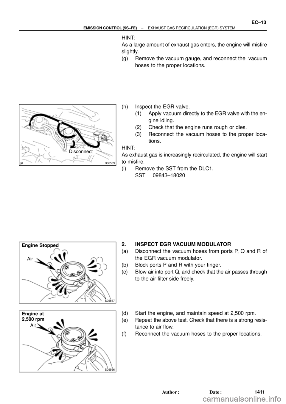
(h) Inspect the EGR valve.
(1) Apply vacuum directly to the EGR valve with the en-
gine idling.
(2) Check that the engine runs rough or dies.
(3) Reconnect the vacuum hoses to the proper loca-
tions.
HINT:
As exhaust gas is increasingly recirculated, the engine will start
to misfire.
(i) Remove the SST from the DLC1.
SST 09843±18020
2. INSPECT EGR VACUUM MODULATOR
(a) Disconnect the vacuum hoses from ports P, Q and R of
the EGR vacuum modulator.
(b) Block ports P and R with your finger.
(c) Blow air into port Q, and check that the air passes through
to the air filter side freely.
(d) Start the engine, and maintain speed at 2,500 rpm.
(e) Repeat the above test. Check that there is a strong resis-
tance to air flow.
(f) Reconnect the vacuum hoses to the proper locations.
Page 3380 of 4770
EC0AV±01
B01082B04812B06707
Type A
Type BGasket
Gasket
B06544
Vacuum
Gauge
S05331
TOYOTA
Hand±Held Tester
DLC3
EC±6
± EMISSION CONTROL (1MZ±FE)EVAPORATIVE EMISSION (EVAP) CONTROL SYSTEM
1421 Author�: Date�:
INSPECTION
1. INSPECT LINES AND CONNECTORS
Visually check for loose connections, sharp bends or damage.
2. INSPECT FUEL TANK FILLER PIPE
Visually check for deformation, cracks or fuel leakage.
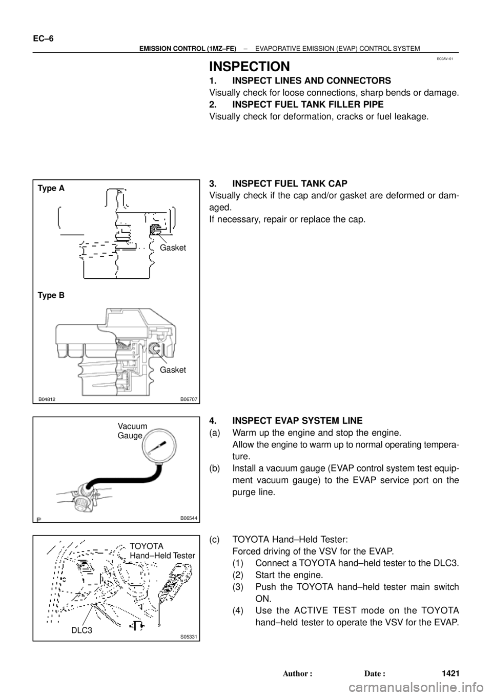
3. INSPECT FUEL TANK CAP
Visually check if the cap and/or gasket are deformed or dam-
aged.
If necessary, repair or replace the cap.
4. INSPECT EVAP SYSTEM LINE
(a) Warm up the engine and stop the engine.
Allow the engine to warm up to normal operating tempera-
ture.
(b) Install a vacuum gauge (EVAP control system test equip-
ment vacuum gauge) to the EVAP service port on the
purge line.
(c) TOYOTA Hand±Held Tester:
Forced driving of the VSV for the EVAP.
(1) Connect a TOYOTA hand±held tester to the DLC3.
(2) Start the engine.
(3) Push the TOYOTA hand±held tester main switch
ON.
(4) Use the ACTIVE TEST mode on the TOYOTA
hand±held tester to operate the VSV for the EVAP.
Page 3381 of 4770
B06722
Battery
B06545
B06543
Hose Clipper
Air Drain Hose
± EMISSION CONTROL (1MZ±FE)EVAPORATIVE EMISSION (EVAP) CONTROL SYSTEM
EC±7
1422 Author�: Date�:
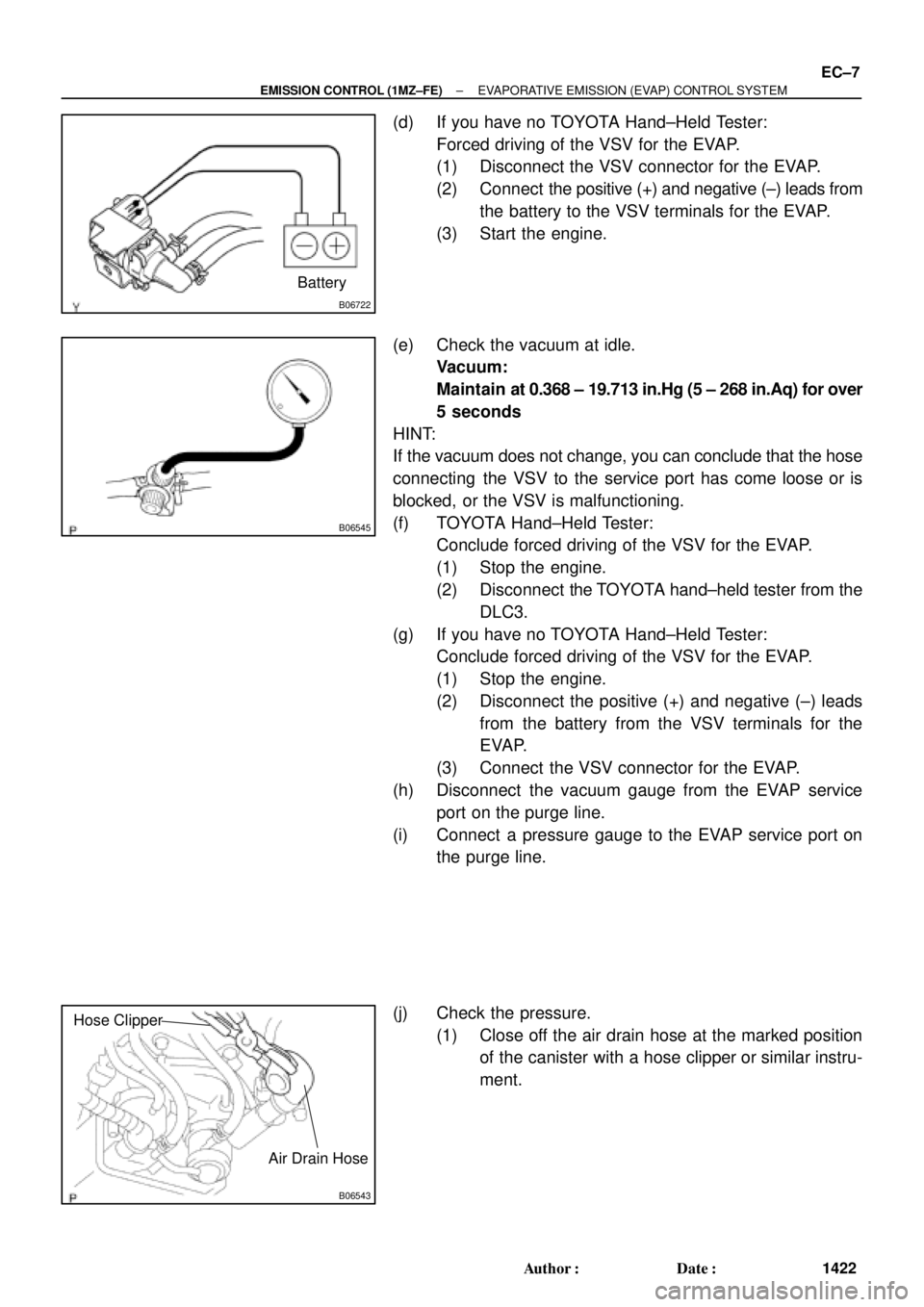
(d) If you have no TOYOTA Hand±Held Tester:
Forced driving of the VSV for the EVAP.
(1) Disconnect the VSV connector for the EVAP.
(2) Connect the positive (+) and negative (±) leads from
the battery to the VSV terminals for the EVAP.
(3) Start the engine.
(e) Check the vacuum at idle.
Vacuum:
Maintain at 0.368 ± 19.713 in.Hg (5 ± 268 in.Aq) for over
5 seconds
HINT:
If the vacuum does not change, you can conclude that the hose
connecting the VSV to the service port has come loose or is
blocked, or the VSV is malfunctioning.
(f) TOYOTA Hand±Held Tester:
Conclude forced driving of the VSV for the EVAP.
(1) Stop the engine.
(2) Disconnect the TOYOTA hand±held tester from the
DLC3.
(g) If you have no TOYOTA Hand±Held Tester:
Conclude forced driving of the VSV for the EVAP.
(1) Stop the engine.
(2) Disconnect the positive (+) and negative (±) leads
from the battery from the VSV terminals for the
EVAP.
(3) Connect the VSV connector for the EVAP.
(h) Disconnect the vacuum gauge from the EVAP service
port on the purge line.
(i) Connect a pressure gauge to the EVAP service port on
the purge line.
(j) Check the pressure.
(1) Close off the air drain hose at the marked position
of the canister with a hose clipper or similar instru-
ment.
Page 3393 of 4770
EM07X±05
S04994
CO/HC Meter
± ENGINE MECHANICAL (5S±FE)CO/HC
EM±1
1173 Author�: Date�:
CO/HC
INSPECTION
HINT:
This check is used only to determine whether or not the idle CO/
HC complies with regulations.
1. INITIAL CONDITIONS
(a) Engine at normal operating temperature
(b) Air cleaner installed
(c) All pipes and hoses of air induction system connected
(d) All accessories switched OFF
(e) All vacuum lines properly connected
HINT:
All vacuum hoses for EGR system, etc. should be properly con-
nected.
(f) SFI system wiring connectors fully plugged
(g) Ignition timing checked correctly
(h) Transmission in neutral position
(i) Tachometer and CO/HC meter calibrated by hand
2. START ENGINE
3. RACE ENGINE AT 2,500 RPM FOR APPROX. 180 SE-
CONDS
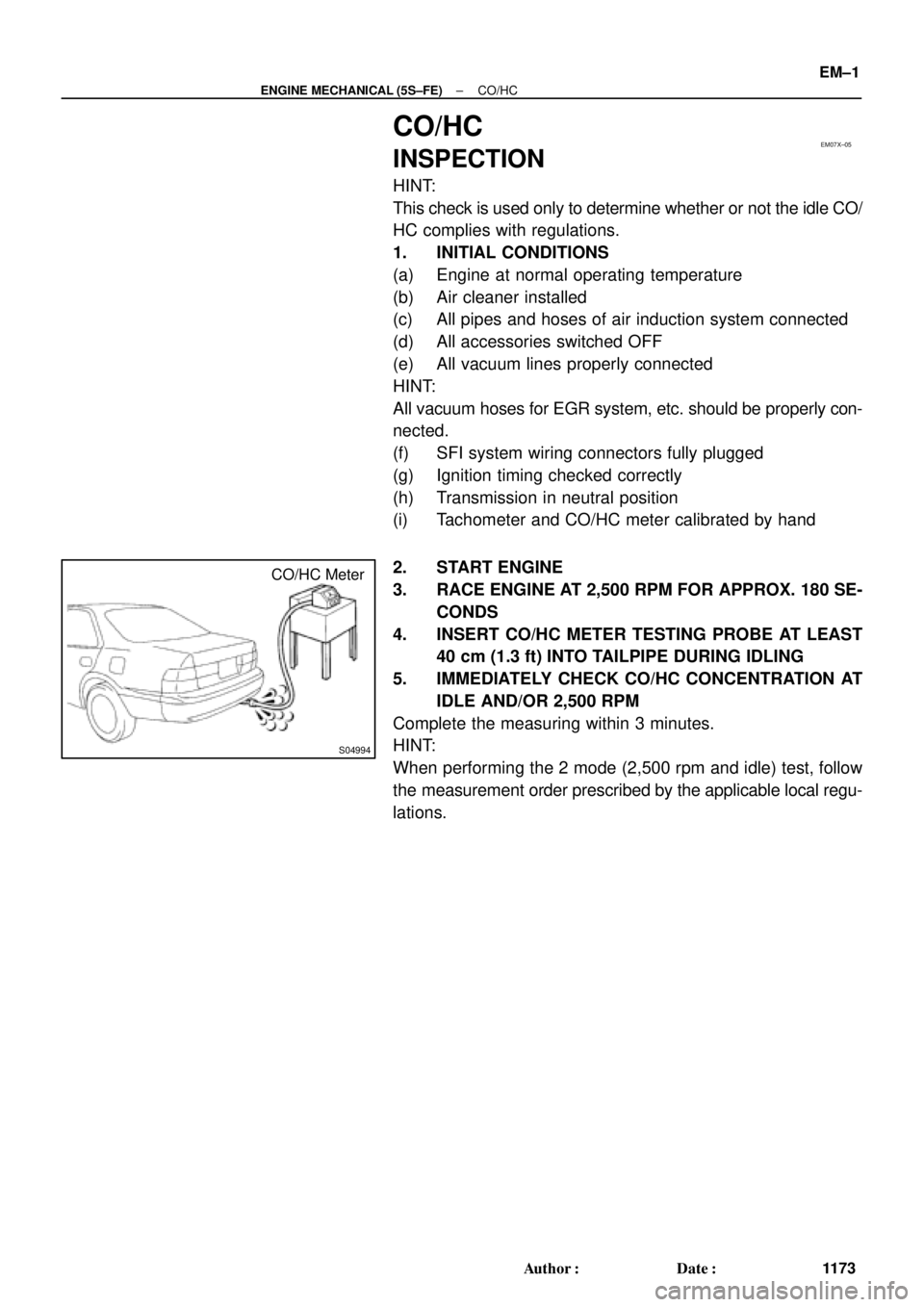
4. INSERT CO/HC METER TESTING PROBE AT LEAST
40 cm (1.3 ft) INTO TAILPIPE DURING IDLING
5. IMMEDIATELY CHECK CO/HC CONCENTRATION AT
IDLE AND/OR 2,500 RPM
Complete the measuring within 3 minutes.
HINT:
When performing the 2 mode (2,500 rpm and idle) test, follow
the measurement order prescribed by the applicable local regu-
lations.
Page 3394 of 4770

EM±2
± ENGINE MECHANICAL (5S±FE)CO/HC
1174 Author�: Date�:
If the CO/HC concentration does not comply with regulations,
troubleshoot in the order given below.
(1) Check oxygen sensor operation.
(See page DI±66)
(2) See the table below for possible causes, then in-
spect and correct the applicable causes if neces-
sary.
COHCSymptomCauses
NormalHighRough idle1. Faulty ignitions:
� Incorrect timing
� Fouled, shorted or improperly gapped plugs
� Open or crossed hi
gh±tension cords� Oen or crossed high±tension cords
2. Incorrect valve clearance
3. Leaky EGR valve
4. Leaky intake and exhaust valves
5. Leaky cylinder
LowHighRough idle
(Fluctuating HC reading)1. Vacuum leaks:
� PCV hose
� EGR valve
� Intake manifold
� Throttle body
� IAC valve
� Brake booster line
2. Lean mixture causing misfire
HighHighRough idle
(Black smoke from exhaust)1. Restricted air filter
2. Faulty SFI system
� Faulty pressure regulator
� Defective ECT sensor
� Defective IAT sensor
� Faulty ECM
� Faulty injector
� Faulty throttle position sensor
� MAP sensor