Page 3439 of 4770
CYLINDER HEAD
EM±47
1219 Author�: Date�:
(c) Using a spring tester, measure the tension of the valve
spring at the specif")
EM0281
EM1628
EM2011
EM2538
EM3322
Free Distance
± ENGINE MECHANICAL (5S±FE)CYLINDER HEAD
EM±47
1219 Author�: Date�:
(c) Using a spring tester, measure the tension of the valve
spring at the specified installed length.
Installed tension:
164 ± 189 N (16.7 ± 19.3 kgf, 36.8 ± 42.5 lbf)
at 34.7 mm (1.366 in.)
If the installed tension is not as specified, replace the valve
spring.
10. INSPECT CAMSHAFTS
(a) Inspect the circle runout.
(1) Place the camshaft on V±blocks.
(2) Using a dial indicator, measure the circle runout at
the center journal.
Maximum circle runout: 0.04 mm (0.0016 in.)
If the circle runout is greater than maximum, replace the cam-
shaft.
(b) Using a micrometer, measure the cam lobe height.
Standard cam lobe height:
Intake42.01 ± 42.11 mm (1.6539 ± 1.6579 in.)
Exhaust40.06 ± 40.16 mm (1.5772 ± 1.5811 in.)
Minimum cam lobe height:
Intake41.90 mm (1.6496 in.)
Exhaust39.95 mm (1.5728 in.)
If the cam lobe height is less than minimum, replace the cam-
shaft.
(c) Using a micrometer, measure the journal diameter.
Journal diameter:
26.959 ± 26.975 mm (1.0614 ± 1.0620 in.)
If the journal diameter is not as specified, check the oil clear-
ance.
(d) Using vernier calipers, measure the free distance be-
tween the gear spring ends.
Free distance: 22.5 ± 22.9 mm (0.886 ± 0.902 in.)
If the free distance is not as specified, replace the gear spring.
Page 3440 of 4770
CYLINDER HEAD
1220 Author�: Date�:
(e) Inspect the journal oil clearance.
(1) Clean the bearing caps and camshaft journals.
(")
EM3371
Plastigage
P00259
EM3310
P00263
EM±48
± ENGINE MECHANICAL (5S±FE)CYLINDER HEAD
1220 Author�: Date�:
(e) Inspect the journal oil clearance.
(1) Clean the bearing caps and camshaft journals.
(2) Check that bearings for flaking and scoring.
If the bearings are damaged, replace the bearing caps and cyl-
inder head as a set.
(3) Place the camshafts on the cylinder head.
(4) Lay a strip of Plastigage across each of the cam-
shaft journals.
(5) Install the bearing caps. (See page EM±53)
NOTICE:
Do not turn the camshaft.
(6) Remove the bearing caps.
(7) Measure the Plastigage at its widest point.
Standard oil clearance:
0.025 ± 0.062 mm (0.0010 ± 0.0024 in.)
Maximum oil clearance: 0.10 mm (0.0039 in.)
If the oil clearance is greater than maximum, replace the cam-
shaft. If necessary, replace the bearing caps and cylinder head
as a set.
(8) Completely remove the Plastigage.
(f) Inspect the camshaft thrust clearance.
(1) Install the camshaft. (See page EM±53)
(2) Using a dial indicator, measure the thrust clearance
while moving the camshaft back and forth.
Standard thrust clearance:
Intake0.045 ± 0.100 mm (0.0018 ± 0.0039 in.)
Exhaust0.030 ± 0.085 mm (0.0012 ± 0.0033 in.)
Maximum thrust clearance:
Intake0.12 mm (0.0047 in.)
Exhaust0.10 mm (0.0039 in.)
If the thrust clearance is greater than maximum, replace the
camshaft. If necessary, replace the bearing caps and cylinder
head as a set.
Page 3444 of 4770
CYLINDER HEAD
1224 Author�: Date�:
REASSEMBLY
HINT:
�Thoroughly clean all parts to be assemb")
EM0YM±01
P03274
SST
Z02903
Intake Exhaust
Gray
Black
P03265
SST
P03276
EM±52
± ENGINE MECHANICAL (5S±FE)CYLINDER HEAD
1224 Author�: Date�:
REASSEMBLY
HINT:
�Thoroughly clean all parts to be assembled.
�Before installing the parts, apply new engine oil to all slid-
ing and rotating surfaces.
�Replace all gaskets and oil seals with new ones.
1. INSTALL VALVES
(a) Using SST, push in a new oil seal.
SST 09201±41020
HINT:
The intake valve oil seal is gray and the exhaust valve oil seal
is black.
(b) Install the valve, spring seat, valve spring and spring re-
tainer.
(c) Using SST, compress the valve spring and place the 2
keepers around the valve stem.
SST 09202±70020 (09202±00010)
(d) Using a plastic±faced hammer, lightly tap the valve stem
tip to assure a proper fit.
2. INSTALL VALVE LIFTERS AND SHIMS
(a) Install the valve lifter and shim.
(b) Check that the valve lifter rotates smoothly by hand.
3. INSTALL CAMSHAFT POSITION SENSOR AS-
SEMBLY
Install the sensor assembly with the bolt.
Torque: 9.5 N´m (97 kgf´cm, 84 in.´lbf)
Page 3445 of 4770
CYLINDER HEAD
EM±53
1225 Author�: Date�:
INSTALLATION
1. PLACE CYLINDER HEAD ON CYLIND")
EM08D±04
A07355
Z02750
1
10 24 6 839
7 5
S01690
90°
Front
Painted
Mark90°
P03279
± ENGINE MECHANICAL (5S±FE)CYLINDER HEAD
EM±53
1225 Author�: Date�:
INSTALLATION
1. PLACE CYLINDER HEAD ON CYLINDER BLOCK
(a) Place a new cylinder head gasket on the cylinder block.
NOTICE:
Be careful of the installation direction.
(b) Place the cylinder head on the cylinder head gasket.
2. INSTALL CYLINDER HEAD BOLTS
HINT:
�The cylinder head bolts are tightened in 2 progressive
steps (steps (b) and (d)).
�If any cylinder head bolt is broken or deformed, replace
it.
(a) Apply a light coat of engine oil on the threads and under
the heads of the cylinder head bolts.
(b) Install and uniformly tighten the 10 cylinder head bolts
and plate washers in several passes, in the sequence
shown.
Torque: 49 N´m (500 kgf´cm, 36 ft´lbf)
If any one of the cylinder head bolts does not meet the torque
specification, replace the cylinder head bolt.
(c) Mark the front of the cylinder head bolt head with paint.
(d) Retighten the cylinder head bolts 90° in the numerical or-
der shown.
(e) Check that the painted mark is now at a 90° angle to the
front.
(f) Install the 2 bolts holding the water bypass pipe to the cyl-
inder head.
Torque: 19 N´m (195 kgf´cm, 14 ft´lbf)
(g) Connect the camshaft position sensor connector.
3. INSTALL SPARK PLUG TUBES
(a) Clean the cylinder head tube holes of any residual adhe-
sive, oil or foreign particles. Remove any oil with kerosene
or gasoline.
(b) Screw the threads of the spark plug tube coated with
adhesive into the cylinder head.
(c) Using the spark plug tube nut and a 30 mm socket
wrench, tighten the spark plug tubes.
Torque: 49 N´m (500 kgf´cm, 36 ft´lbf)
Page 3449 of 4770
CYLINDER HEAD
EM±57
1229 Author�: Date�:
(9) Remove the")
P03445
Drive Gear
Sub±Gear Service
Bolt
EM7797
Seal Packing
P03282
P03283
: Seal Packing
S05932
Marking
15° 15°
± ENGINE MECHANICAL (5S±FE)CYLINDER HEAD
EM±57
1229 Author�: Date�:
(9) Remove the service bolt.
6. CHECK AND ADJUST VALVE CLEARANCE
(See page EM±4)
Turn the camshaft and position the cam lobe upward, and in-
spect and adjust the valve clearance.
7. INSTALL SEMI±CIRCULAR PLUGS
(a) Remove any old packing (FIPG) material.
(b) Apply seal packing to the semi±circular plug grooves.
Seal packing: Part No. 08826±00080 or equivalent
(c) Install the 2 semi±circular plugs to the cylinder head.
8. INSTALL CYLINDER HEAD COVER
(a) Remove any old packing (FIPG) material.
(b) Apply seal packing to the cylinder head as shown in the
illustration.
Seal packing: Part No. 08826±00080 or equivalent
(c) Install the gasket to the head cover.
(d) Install the head cover with the 4 grommets and nuts. Uni-
formly tighten the nuts in several passes.
Torque: 44 N´m (450 kgf´cm, 33 ft´lbf)
HINT:
Install the grommets so that their markings are as shown in the
illustration.
Page 3451 of 4770
S06009
Upward
ConnectorTurn
Push
S05935New Insulator
Spacer
S06002
S06003
Upward
ConnectorTurn
S06001
± ENGINE MECHANICAL (5S±FE)CYLINDER HEAD
EM±59
1231 Author�: Date�:
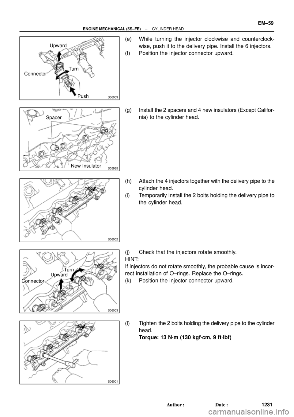
(e) While turning the injector clockwise and counterclock-
wise, push it to the delivery pipe. Install the 6 injectors.
(f) Position the injector connector upward.
(g) Install the 2 spacers and 4 new insulators (Except Califor-
nia) to the cylinder head.
(h) Attach the 4 injectors together with the delivery pipe to the
cylinder head.
(i) Temporarily install the 2 bolts holding the delivery pipe to
the cylinder head.
(j) Check that the injectors rotate smoothly.
HINT:
If injectors do not rotate smoothly, the probable cause is incor-
rect installation of O±rings. Replace the O±rings.
(k) Position the injector connector upward.
(l) Tighten the 2 bolts holding the delivery pipe to the cylinder
head.
Torque: 13 N´m (130 kgf´cm, 9 ft´lbf)
Page 3455 of 4770
S05300
TMC
Made
TMMK
Made
S05282
± ENGINE MECHANICAL (5S±FE)CYLINDER HEAD
EM±63
1235 Author�: Date�:
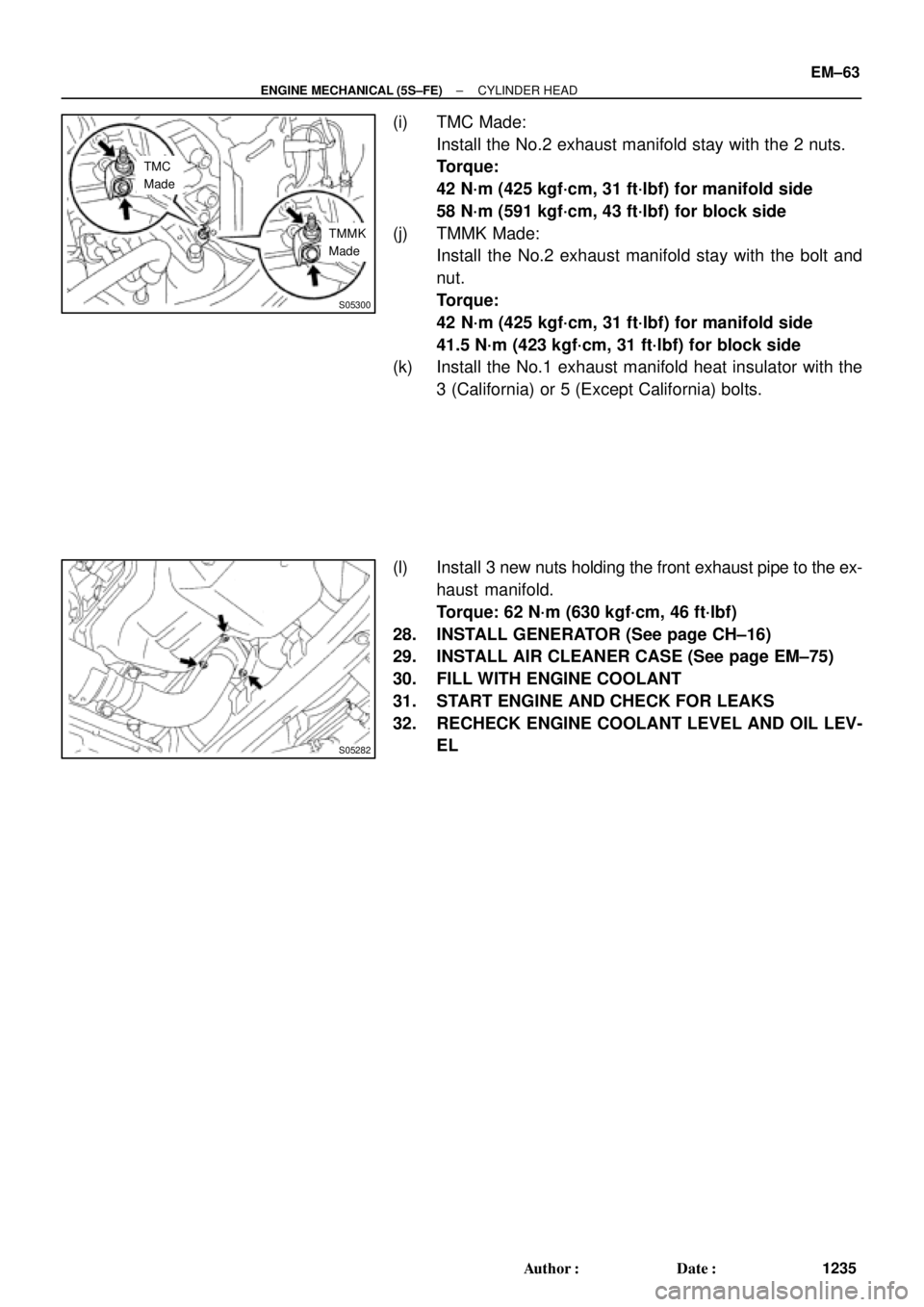
(i) TMC Made:
Install the No.2 exhaust manifold stay with the 2 nuts.
Torque:
42 N´m (425 kgf´cm, 31 ft´lbf) for manifold side
58 N´m (591 kgf´cm, 43 ft´lbf) for block side
(j) TMMK Made:
Install the No.2 exhaust manifold stay with the bolt and
nut.
Torque:
42 N´m (425 kgf´cm, 31 ft´lbf) for manifold side
41.5 N´m (423 kgf´cm, 31 ft´lbf) for block side
(k) Install the No.1 exhaust manifold heat insulator with the
3 (California) or 5 (Except California) bolts.
(l) Install 3 new nuts holding the front exhaust pipe to the ex-
haust manifold.
Torque: 62 N´m (630 kgf´cm, 46 ft´lbf)
28. INSTALL GENERATOR (See page CH±16)
29. INSTALL AIR CLEANER CASE (See page EM±75)
30. FILL WITH ENGINE COOLANT
31. START ENGINE AND CHECK FOR LEAKS
32. RECHECK ENGINE COOLANT LEVEL AND OIL LEV-
EL
Page 3467 of 4770
ENGINE UNIT
EM±75
1247 Author�: Date�:
INSTALLATION
1. INSTALL NO.1 REAR END PLATE
Install the")
EM08G±04
EM7333
Z18989
M/T
1
3
5
8
2 4 67
S05531
Wire
Bracket
Ground
Strap
± ENGINE MECHANICAL (5S±FE)ENGINE UNIT
EM±75
1247 Author�: Date�:
INSTALLATION
1. INSTALL NO.1 REAR END PLATE
Install the end plate with the bolt.
Torque: 9.3 N´m (95 kgf´cm, 82 in.´lbf)
2. M/T:
INSTALL FLYWHEEL
(a) Apply adhesive to 2 or 3 threads of the bolt end.
Adhesive:
Part No. 08833±00070, THREE BOND 1324 or equiva-
lent
(b) Install the flywheel on the crankshaft.
(c) Install and uniformly tighten the 8 bolts in several passes,
in the sequence shown.
Torque: 88 N´m (900 kgf´cm, 65 ft´lbf)
3. A/T:
INSTALL DRIVE PLATE (See step 2)
Torque: 83 N´m (850 kgf´cm, 61 ft´lbf)
4. M/T:
INSTALL CLUTCH DISC AND COVER
5. A/T:
CHECK TORQUE CONVERTER CLUTCH INSTALLA-
TION (A140E: See page AX±25)
6. INSTALL TRANSAXLE TO ENGINE
(a) Attach the transaxle to the engine.
(b) Install the ground strap, wire bracket and 4 bolts.
Torque:
46 N´m (470 kgf´cm, 34 ft´lbf) for 14 mm head
64 N´m (650 kgf´cm, 47 ft´lbf) for 17 mm head