Page 3414 of 4770
TIMING BELT
1194 Author�: Date�:
INSPECTION
1. INSPECT TIMING BELT
NOTICE:
�Do not bend, twist or turn the t")
EM085±03
EM3336
No!
S01519
Turn
Seal
P15243Free Length EM±22
± ENGINE MECHANICAL (5S±FE)TIMING BELT
1194 Author�: Date�:
INSPECTION
1. INSPECT TIMING BELT
NOTICE:
�Do not bend, twist or turn the timing belt inside out.
�Do not allow the timing belt to come into contact with
oil, water or steam.
�Do not utilize timing belt tension when installing or re-
moving the mounting bolt of the camshaft timing
pulley.
If there are any defects as shown in the illustration, check these
points:
(a) Premature parting
�Check for proper installation.
�Check the timing cover gasket for damage and
proper installation.
(b) If the belt teeth are cracked or damaged, check to see if
either camshaft or water pump is locked.
(c) If there is noticeable wear or cracks on the belt face,
check to see if there are nicks on the side of the idler
pulley lock.
(d) If there is wear or damage on only one side of the belt,
check the belt guide and the alignment of each pulley.
(e) If there is noticeable wear on the belt teeth, check the tim-
ing cover for damage and check gasket has been
installed correctly and for foreign material on the pulley
teeth.
If necessary, replace the timing belt.
2. INSPECT IDLER PULLEYS
(a) Visually check the seal portion of the idler pulley for oil
leakage.
If leakage is found, replace the idler pulley.
(b) Check that the idler pulley turns smoothly.
If necessary, replace the idler pulley.
3. INSPECT TENSION SPRING
(a) Measure the free length of tension spring.
Free length: 42.0 mm (1.654 in.)
If the free length is not as specified, replace the tension spring.
(b) Measure the tension of the tension spring at the specified
installed length.
Installed tension (at 50.5 mm (1.988 in.)):
32 ± 37 N (3.25 ± 3.75 kgf, 7.2 ± 8.3 lbf)
If the installed tension is not as specified, replace the tension
spring.
Page 3415 of 4770
TIMING BELT
EM±23
1195 Author�: Date�:
INSTALLATION
1. INSTALL OIL PUMP PULLEY
(")
EM086±04
S05576
SST
S05577
Angle
Sensor
Inward
S05571
35 mm
S05616
42 mm
S05926
Pry
Move
± ENGINE MECHANICAL (5S±FE)TIMING BELT
EM±23
1195 Author�: Date�:
INSTALLATION
1. INSTALL OIL PUMP PULLEY
(a) Align the cutouts of the pulley and shaft, and slide on the
pulley.
(b) Using SST, install the pulley nut.
SST 09960±10010 (09962±01000, 09963±00500)
Torque: 24 N´m (245 kgf´cm, 18 ft´lbf)
2. INSTALL CRANKSHAFT TIMING PULLEY
(a) Align the timing pulley set key with the key groove of the
pulley.
(b) Slide on the timing pulley, facing the angle sensor inward.
NOTICE:
Do not scratch the angle sensor of the timing pulley.
3. INSTALL NO.2 IDLER PULLEY
(a) Install the pulley with the bolt.
Torque: 42 N´m (425 kgf´cm, 31 ft´lbf)
HINT:
Use the 35 mm (1.38 in.) long bolt.
(b) Check that the idler pulley moves smoothly.
4. TEMPORARILY INSTALL NO.1 IDLER PULLEY AND
TENSION SPRING
(a) Align the bracket pin hole with the pivot pin.
(b) Install the pulley with the bolt. Do not tighten the bolt yet.
HINT:
Use the 42 mm (1.65 in.) long bolt.
(c) Install the tension spring.
(d) Pry the pulley toward the left as far as it will go, and tighten
the bolt.
(e) Check that the idler pulley moves smoothly.
Page 3416 of 4770
 EM±24
± ENGINE MECHANICAL (5S±FE)TIMING BELT
1196 Author�: Date�:
5. TEMPORARILY INSTALL TIMING BELT
NOTICE:
The engine should be cold.
(a) Us")
S05574
S05944
S05578
P25230Length = 660 mm (25.98 in.) EM±24
± ENGINE MECHANICAL (5S±FE)TIMING BELT
1196 Author�: Date�:
5. TEMPORARILY INSTALL TIMING BELT
NOTICE:
The engine should be cold.
(a) Using the crankshaft pulley bolt, turn the crankshaft and
align the timing marks of the crankshaft timing pulley and
oil pump body.
(b) Remove any oil or water on the crankshaft pulley, oil
pump pulley, water pump pulley, No.1 idler pulley and
No.2 idler pulley, and keep them clean.
(c) Install the timing belt on the crankshaft timing pulley, oil
pump pulley, No.1 idler pulley, water pump pulley and
No.2 idler pulley.
HINT:
When re±using timing belt:
Align the points marked during removal, and install the belt with
the arrow pointing in the direction of engine revolution.
6. INSTALL TIMING BELT GUIDE
Install the guide, facing the cup side outward.
7. INSTALL NO.1 TIMING BELT COVER
(a) Check that the timing belt cover gasket has no cracks or
peeling, etc.
If the gasket has cracks or peeling, etc., replace it using these
steps:
(1) Using a screwdriver and gasket scraper, remove all
the old gasket material.
(2) Thoroughly clean all components to remove all the
loose material.
(3) Remove the backing paper from a new gasket and
install the gasket evenly to the part of the timing belt
cover shaded black in the illustration.
(4) After installing the gasket, press down on it so that
the adhesive firmly sticks to the timing belt cover.
Page 3418 of 4770
S05594
SST
A02592
S05582
S05931
S05581
Loosen EM±26
± ENGINE MECHANICAL (5S±FE)TIMING BELT
1198 Author�: Date�:
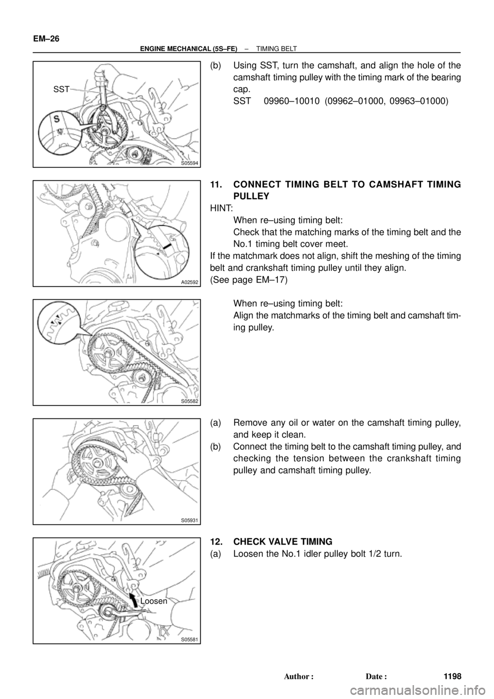
(b) Using SST, turn the camshaft, and align the hole of the
camshaft timing pulley with the timing mark of the bearing
cap.
SST 09960±10010 (09962±01000, 09963±01000)
11. CONNECT TIMING BELT TO CAMSHAFT TIMING
PULLEY
HINT:
�When re±using timing belt:
Check that the matching marks of the timing belt and the
No.1 timing belt cover meet.
If the matchmark does not align, shift the meshing of the timing
belt and crankshaft timing pulley until they align.
(See page EM±17)
�When re±using timing belt:
Align the matchmarks of the timing belt and camshaft tim-
ing pulley.
(a) Remove any oil or water on the camshaft timing pulley,
and keep it clean.
(b) Connect the timing belt to the camshaft timing pulley, and
checking the tension between the crankshaft timing
pulley and camshaft timing pulley.
12. CHECK VALVE TIMING
(a) Loosen the No.1 idler pulley bolt 1/2 turn.
Page 3419 of 4770

Length = 230 mm (9.06 in.)
± ENGINE MECHANICAL (5S±FE)TIMING BELT
EM±27
1199 Author�: Date�:
(b) Slowly turn the crankshaft")
S05587
Turn
S05598
S05586
Turn
S05585
S01710
Length = 735 mm (28.94 in.)
Length = 230 mm (9.06 in.)
± ENGINE MECHANICAL (5S±FE)TIMING BELT
EM±27
1199 Author�: Date�:
(b) Slowly turn the crankshaft pulley 2 revolutions TDC to
TDC.
NOTICE:
Always turn the crankshaft pulley clockwise.
(c) Check that each pulley aligns with the timing marks as
shown in the illustration.
If the timing marks do not align, remove the timing belt and rein-
stall it.
(d) Slowly turn the crankshaft pulley 1 and 7/8 revolutions,
and align its groove with the mark at 45° BTDC (for No.1
cylinder) of the No.1 timing belt cover.
NOTICE:
Always turn the crankshaft pulley clockwise.
(e) Tighten the mounting bolt of the No.1 idler pulley.
Torque: 42 N´m (425 kgf´cm, 31 ft´lbf)
13. INSTALL NO.2 TIMING BELT COVER
(a) Check that the timing belt cover gaskets have no cracks
or peeling, etc.
If the gasket has cracks or peeling, etc., replace it using these
steps:
(1) Using a screwdriver and gasket scraper, remove all
the old gasket material.
(2) Thoroughly clean all components to remove all the
loose material.
Page 3435 of 4770
P03363
Z02749
Cylinder Block Side
Intake Manifold Side
Exhaust Manifold Side
P03269
EM0580
± ENGINE MECHANICAL (5S±FE)CYLINDER HEAD
EM±43
1215 Author�: Date�:
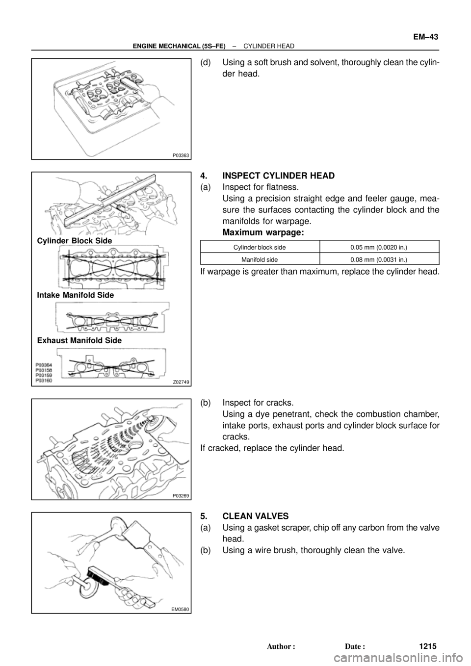
(d) Using a soft brush and solvent, thoroughly clean the cylin-
der head.
4. INSPECT CYLINDER HEAD
(a) Inspect for flatness.
Using a precision straight edge and feeler gauge, mea-
sure the surfaces contacting the cylinder block and the
manifolds for warpage.
Maximum warpage:
Cylinder block side0.05 mm (0.0020 in.)
Manifold side0.08 mm (0.0031 in.)
If warpage is greater than maximum, replace the cylinder head.
(b) Inspect for cracks.
Using a dye penetrant, check the combustion chamber,
intake ports, exhaust ports and cylinder block surface for
cracks.
If cracked, replace the cylinder head.
5. CLEAN VALVES
(a) Using a gasket scraper, chip off any carbon from the valve
head.
(b) Using a wire brush, thoroughly clean the valve.
Page 3436 of 4770
CYLINDER HEAD
1216 Author�: Date�:
6. INSPECT VALVE STEMS AND GUIDE BUSHINGS
(a) Using a caliper gauge, measure")
Z02754
Z00052
Z00054
44.5°
EM0181
Margin Thickness EM±44
± ENGINE MECHANICAL (5S±FE)CYLINDER HEAD
1216 Author�: Date�:
6. INSPECT VALVE STEMS AND GUIDE BUSHINGS
(a) Using a caliper gauge, measure the inside diameter of the
guide bushing.
Bushing inside diameter:
6.010 ± 6.030 mm (0.2366 ± 0.2374 in.)
(b) Using a micrometer, measure the diameter of the valve
stem.
Valve stem diameter:
Intake5.970 ± 5.985 mm (0.2350 ± 0.2356 in.)
Exhaust5.965 ± 5.980 mm (0.2348 ± 0.2354 in.)
(c) Subtract the valve stem diameter measurement from the
guide bushing inside diameter measurement.
Standard oil clearance:
Intake0.025 ± 0.060 mm (0.0010 ± 0.0024 in.)
Exhaust0.030 ± 0.065 mm (0.0012 ± 0.0026 in.)
Maximum oil clearance:
Intake0.08 mm (0.0031 in.)
Exhaust0.10 mm (0.0039 in.)
If the clearance is greater than maximum, replace the valve and
guide bushing. (See page EM±50)
7. INSPECT AND GRIND VALVES
(a) Grind the valve enough to remove pits and carbon.
(b) Check that the valve is ground to the correct valve face
angle.
Valve face angle: 44.5°
(c) Check the valve head margin thickness.
Standard margin thickness:
0.8 ± 1.2 mm (0.031 ± 0.047 in.)
Minimum margin thickness: 0.5 mm (0.020 in.)
If the margin thickness is less than minimum, replace the valve.
Page 3437 of 4770
CYLINDER HEAD
EM±45
1217 Author�: Date�:
(d) Check the valve overall length.
Standard overall length:")
EM2534
Overall Length
EM0255
P03272
45° Carbide
Cutter
Z00055
Width
± ENGINE MECHANICAL (5S±FE)CYLINDER HEAD
EM±45
1217 Author�: Date�:
(d) Check the valve overall length.
Standard overall length:
Intake97.40 ± 97.80 mm (3.8346 ± 3.8504 in.)
Exhaust98.25 ± 98.65 mm (3.8681 ± 3.8839 in.)
Minimum overall length:
Intake97.1 mm (3.823 in.)
Exhaust98.0 mm (3.858 in.)
If the overall length is less than minimum, replace the valve.
(e) Check the surface of the valve stem tip for wear.
If the valve stem tip is worn, resurface the tip with a grinder or
replace the valve.
NOTICE:
Do not grind off more than the minimum length.
8. INSPECT AND CLEAN VALVE SEATS
(a) Using a 45° carbide cutter, resurface the valve seats.
Remove only enough metal to clean the seats.
(b) Check the valve seating position.
Apply a light coat of prussian blue (or white lead) to the
valve face. Lightly press the valve against the seat. Do not
rotate valve.
(c) Check the valve face and seat for the following:
�If blue appears 360° around the face, the valve is
concentric. If not, replace the valve.
�If blue appears 360° around the valve seat, the
guide and face are concentric. If not, resurface the
seat.
�Check that the seat contact is in the middle of the
valve face with the following width:
1.0 ± 1.4 mm (0.039 ± 0.055 in.)