Page 3509 of 4770
COMPRESSION
EM±3
1289 Author�: Date�:
COMPRESSION
INSPECTION
HINT:
If there is lack of power, excessive oil consumption or poor fuel
ec")
EM04J±03
P19471Compression Gauge
± ENGINE MECHANICAL (1MZ±FE)COMPRESSION
EM±3
1289 Author�: Date�:
COMPRESSION
INSPECTION
HINT:
If there is lack of power, excessive oil consumption or poor fuel
economy, measure the compression pressure.
1. WARM UP AND STOP ENGINE
Allow the engine to warm up to normal operating temperature.
2. REMOVE IGNITION COILS AND HIGH±TENSION
CORDS (See page IG±7)
3. REMOVE SPARK PLUGS
Using a 16 mm plug wrench, remove the 6 spark plugs.
4. CHECK CYLINDER COMPRESSION PRESSURE
(a) Insert a compression gauge into the spark plug hole.
(b) Fully open the throttle.
(c) While cranking the engine, measure the compression
pressure.
HINT:
Always use a fully charged battery to obtain engine speed of
250 rpm or more.
(d) Repeat steps (a) through (c) for each cylinder.
NOTICE:
This measurement must be done in as short a time as pos-
sible.
Compression pressure:
1,500 kPa (15.3 kgf/cm
2, 218 psi)
Minimum pressure: 1,000 kPa (10.2 kgf/cm
2, 145 psi)
Difference between each cylinder:
100 kPa (1.0 kgf/cm
2, 15 psi) or less
(e) If the cylinder compression in 1 or more cylinders is low,
pour a small amount of engine oil into the cylinder through
the spark plug hole and repeat steps (a) through (c) for
cylinders with low compression.
�If adding oil helps the compression, it is likely that
the piston rings and/or cylinder bore are worn or
damaged.
�If pressure stays low, a valve may be sticking or
seating is improper, or there may be leakage past
the gasket.
5. REINSTALL SPARK PLUGS
6. INSTALL IGNITION COILS AND HIGH±TENSION
CORDS (See page IG±8)
Page 3510 of 4770
VALVE CLEARANCE
1290 Author�: Date�:
VALVE CLEARANCE
INSPECTION
HINT:
Inspect and adjust the val")
EM04K±04
P18805
P13074
RH EX
RH IN
LH IN
LH EX 13
6
23
1
6
2Front EM±4
± ENGINE MECHANICAL (1MZ±FE)VALVE CLEARANCE
1290 Author�: Date�:
VALVE CLEARANCE
INSPECTION
HINT:
Inspect and adjust the valve clearance when the engine is cold.
1. REMOVE RH FENDER APRON SEAL
2. DRAIN ENGINE COOLANT
3. REMOVE V±BANK COVER
(a) Using a 5 mm hexagon wrench, remove the 2 nuts.
(b) Disconnect the 2 clips, and remove the cover.
4. REMOVE HIGH±TENSION CODE SET
(See page IG±7)
5. REMOVE AIR INTAKE CHAMBER ASSEMBLY
(See page EM±32)
6. REMOVE IGNITION COILS
7. DISCONNECT RADIATOR HOSE FROM WATER
OUTLET
8. REMOVE CYLINDER HEAD COVERS
(See page EM±32)
9. SET NO.1 CYLINDER TO TDC/COMPRESSION
(a) Turn the crankshaft pulley, and align its groove with the
timing mark º0º of the No.1 timing belt cover.
(b) Check that the valve lifters on the No.1 (IN and EX) are
loose.
If not, turn the crankshaft 1 revolution (360°) and align the mark
as above.
10. INSPECT VALVE CLEARANCE
(a) Check only those valves indicated in the illustration.
(1) Using a feeler gauge, measure the clearance be-
tween the valve lifter and camshaft.
(2) Record out of specification valve clearance mea-
surements. They will be used later to determine the
required replacement adjusting shim.
Valve clearance (Cold):
Intake0.15 ± 0.25 mm (0.006 ± 0.010 in.)
Exhaust0.25 ± 0.35 mm (0.010 ± 0.014 in.)
Page 3511 of 4770
P13072
RH IN
LH IN
LH EX RH EX 5
3
435
4 22Front
P13073
RH IN
LH IN
LH EX RH EX
5 1
4
65
4 1
6 Front
P12919
Upward
Notch
± ENGINE MECHANICAL (1MZ±FE)VALVE CLEARANCE
EM±5
1291 Author�: Date�:
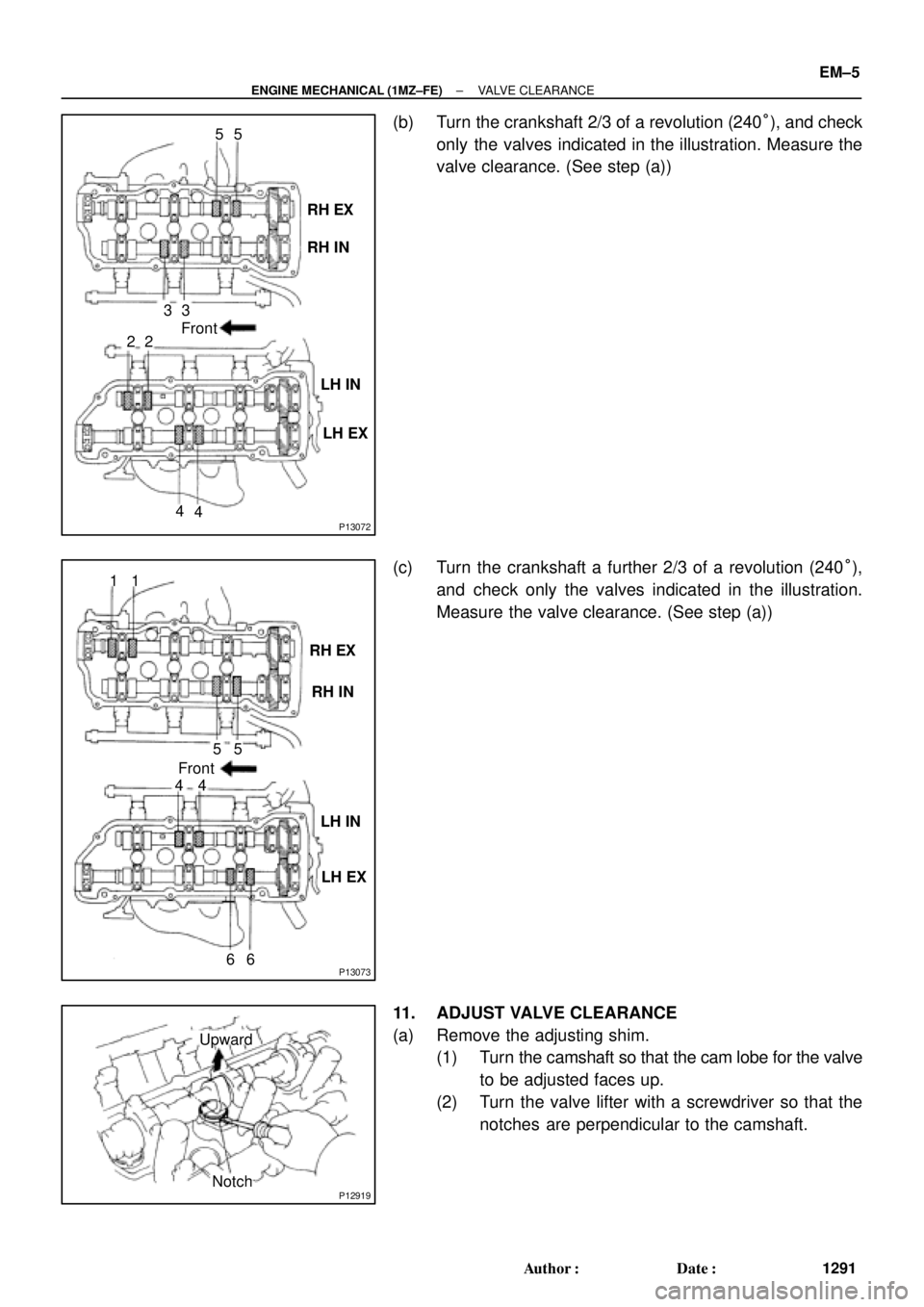
(b) Turn the crankshaft 2/3 of a revolution (240°), and check
only the valves indicated in the illustration. Measure the
valve clearance. (See step (a))
(c) Turn the crankshaft a further 2/3 of a revolution (240°),
and check only the valves indicated in the illustration.
Measure the valve clearance. (See step (a))
11. ADJUST VALVE CLEARANCE
(a) Remove the adjusting shim.
(1) Turn the camshaft so that the cam lobe for the valve
to be adjusted faces up.
(2) Turn the valve lifter with a screwdriver so that the
notches are perpendicular to the camshaft.
Page 3513 of 4770
P12979
SST (A)
SST (B)
± ENGINE MECHANICAL (1MZ±FE)VALVE CLEARANCE
EM±7
1293 Author�: Date�:
(c) Install a new adjusting shim.
(1) Place a new adjusting shim on the valve lifter, with
imprinted numbers facing down.
(2) Press down the valve lifter with SST (A), and re-
move SST (B).
SST 09248±55040 (09248±05410, 09248±05420)
(d) Recheck the valve clearance.
12. REINSTALL CYLINDER HEAD COVERS
(See page EM±57)
13. CONNECT RADIATOR HOSE TO WATER OUTLET
14. REINSTALL IGNITION COILS
15. REINSTALL AIR INTAKE CHAMBER ASSEMBLY
(See page EM±57)
16. INSTALL HIGH±TENSION CORD SET
(See page IG±8)
17. INSTALL V±BANK COVER
18. REFILL WITH ENGINE COOLANT
19. START ENGINE AND CHECK FOR LEAKS
20. REINSTALL RH FENDER APRON SEAL
Page 3516 of 4770
IGNITION TIMING
1296 Author�: Date�:
IGNITION TIMING
INSPECTION
1. WARM UP ENGINE
Allow")
EM04L±03
S05358
Hand±Held Tester TOYOTA
S04529
E1DLC1
SST
TE1
DLC1
A06644
EM±10
± ENGINE MECHANICAL (1MZ±FE)IGNITION TIMING
1296 Author�: Date�:
IGNITION TIMING
INSPECTION
1. WARM UP ENGINE
Allow the engine to warm up to normal operating temperature.
2. CONNECT TOYOTA HAND±HELD TESTER OR
OBDII SCAN TOOL
(a) Connect a TOYOTA hand±held tester or OBDII scan tool
to the DLC3.
(b) Please refer to the TOYOTA hand±held tester or OBDII
scan tool operator's manual for further details.
3. CONNECT TIMING LIGHT TO ENGINE
Connect the tester probe of a timing light to the No.1 high±ten-
sion cord for No.4 cylinder.
4. CHECK IDLE SPEED
(a) Race the engine speed at 2,500 rpm for approx. 90 se-
conds.
(b) Check the idle speed.
Idle speed: 700 ± 50 rpm
5. INSPECT IGNITION TIMING
(a) Using SST, connect terminals TE1 and E1 of the DLC1.
SST 09843±18020
(b) Using a timing light, check the ignition timing.
Ignition timing: 8 ± 12° BTDC @ idle
(Transmission in neutral position)
(c) Remove the SST from the DLC1.
SST 09843±18020
Page 3517 of 4770
± ENGINE MECHANICAL (1MZ±FE)IGNITION TIMING
EM±11
1297 Author�: Date�:
6. FURTHER CHECK IGNITION TIMING
Ignition timing: 7 ± 24° BTDC @ idle
(Transmission in neutral position)
HINT:
The timing mark moves in a range between 7° and 24°.
7. DISCONNECT TIMING LIGHT FROM ENGINE
8. DISCONNECT TOYOTA HAND±HELD TESTER OR
OBDII SCAN TOOL
Page 3518 of 4770
EM0YN±01
EM±12
± ENGINE MECHANICAL (1MZ±FE)IDLE SPEED
1298 Author�: Date�:
IDLE SPEED
INSPECTION
1. INITIAL CONDITIONS
(a) Engine at normal operating temperature
(b) Air cleaner installed
(c) All pipes and hoses of air induction system connected
(d) All accessories switched OFF
(e) All vacuum lines properly connected
HINT:
All vacuum hoses for EGR system, etc. should be properly connected.
(f) SFI system wiring connectors fully plugged
(g) Ignition timing check correctly
(h) Transmission in neutral position
2. CONNECT TOYOTA HAND±HELD TESTER OR OBDII SCAN TOOL (See page EM±10)
3. INSPECT IDLE SPEED
(a) Race the engine speed at 2,500 rpm for approx. 90 seconds.
(b) Check the idle speed.
Idle speed: 700 ± 50 rpm
If the idle speed is not as specified, check the IAC valve and air intake system.
4. DISCONNECT TOYOTA HAND±HELD TESTER OR OBDII SCAN TOOL
Page 3522 of 4770
P18820
A01800
Clamp
Clamp
P18814
P18808
A05052
EM±16
± ENGINE MECHANICAL (1MZ±FE)TIMING BELT
1302 Author�: Date�:
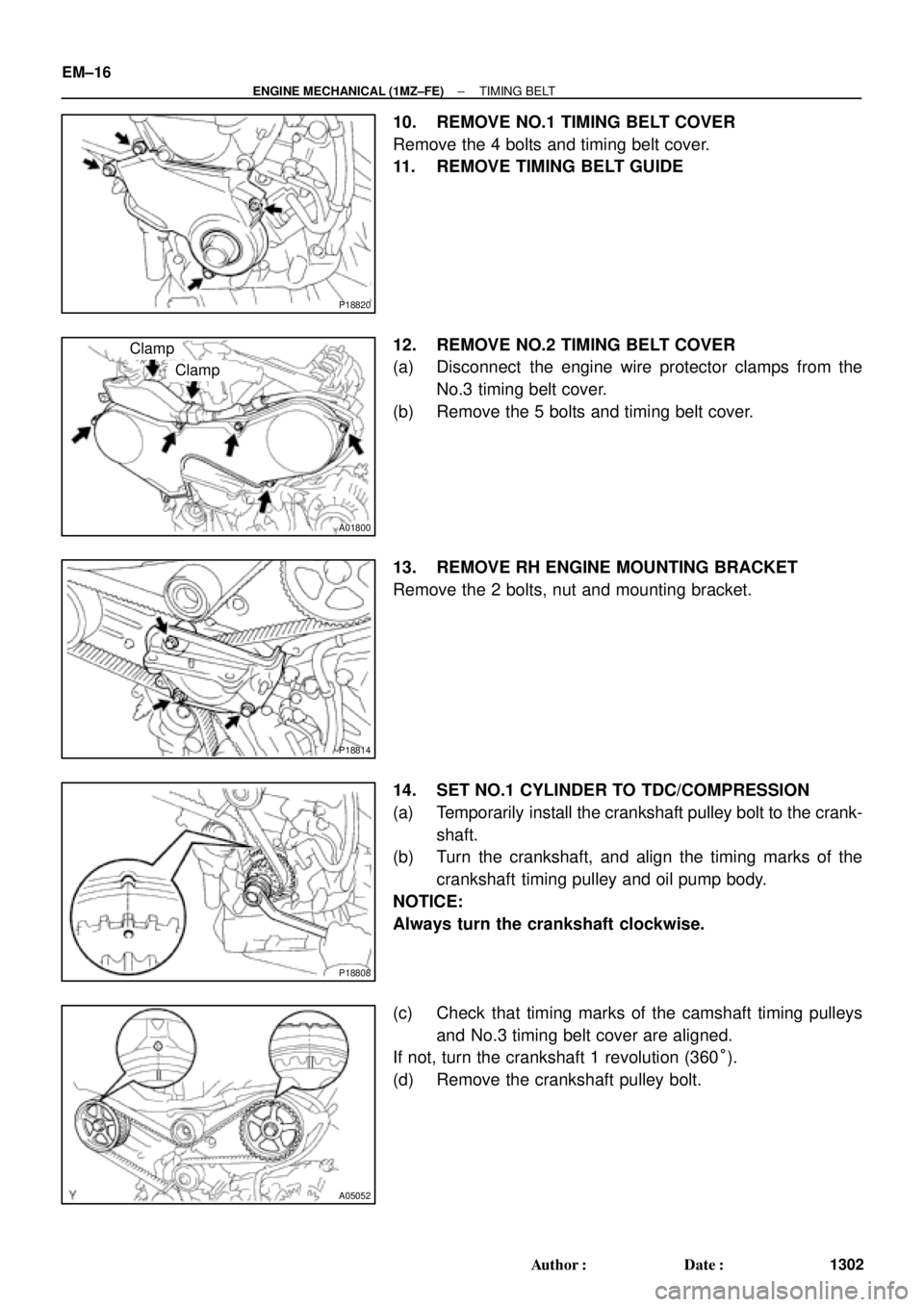
10. REMOVE NO.1 TIMING BELT COVER
Remove the 4 bolts and timing belt cover.
11. REMOVE TIMING BELT GUIDE
12. REMOVE NO.2 TIMING BELT COVER
(a) Disconnect the engine wire protector clamps from the
No.3 timing belt cover.
(b) Remove the 5 bolts and timing belt cover.
13. REMOVE RH ENGINE MOUNTING BRACKET
Remove the 2 bolts, nut and mounting bracket.
14. SET NO.1 CYLINDER TO TDC/COMPRESSION
(a) Temporarily install the crankshaft pulley bolt to the crank-
shaft.
(b) Turn the crankshaft, and align the timing marks of the
crankshaft timing pulley and oil pump body.
NOTICE:
Always turn the crankshaft clockwise.
(c) Check that timing marks of the camshaft timing pulleys
and No.3 timing belt cover are aligned.
If not, turn the crankshaft 1 revolution (360°).
(d) Remove the crankshaft pulley bolt.