Page 3551 of 4770
CYLINDER HEAD
EM±45
1331 Author�: Date�:
9. INSPECT VALVE STEMS AND GUIDE BUSHINGS
(a) Using a caliper gauge, measure")
P12754
Z00052
Z00054
44.5°
EM0181
Margin Thickness
± ENGINE MECHANICAL (1MZ±FE)CYLINDER HEAD
EM±45
1331 Author�: Date�:
9. INSPECT VALVE STEMS AND GUIDE BUSHINGS
(a) Using a caliper gauge, measure the inside diameter of the
guide bushing.
Bushing inside diameter:
5.510 ± 5.530 mm (0.2169 ± 0.2177 in.)
(b) Using a micrometer, measure the diameter of the valve
stem.
Valve stem diameter:
Intake5.470 ± 5.485 mm (0.2154 ± 0.2159 in.)
Exhaust5.465 ± 5.480 mm (0.2152 ± 0.2157 in.)
(c) Subtract the valve stem diameter measurement from the
guide bushing guide bushing inside diameter measure-
ment.
Standard oil clearance:
Intake0.025 ± 0.060 mm (0.0010 ± 0.0024 in.)
Exhaust0.030 ± 0.065 mm (0.0012 ± 0.0026 in.)
Maximum oil clearance:
Intake0.08 mm (0.0031 in.)
Exhaust0.10 mm (0.0039 in.)
If the clearance is greater than maximum, replace the valve and
guide bushing.
10. INSPECT AND GRIND VALVES
(a) Grind the valve enough to remove pits and carbon.
(b) Check that the valve is ground to the correct valve face
angle.
Valve face angle: 44.5°
(c) Check the valve head margin thickness.
Standard margin thickness: 1.0 mm (0.039 in.)
Minimum margin thickness: 0.5 mm (0.020 in.)
If the margin thickness is less than minimum, replace the valve.
Page 3552 of 4770
CYLINDER HEAD
1332 Author�: Date�:
(d) Check the valve overall length.
Standard over")
EM2534
Overall Length
EM0255
P12704
P12729
Width
Z03988
45°
1.0 ± 1.4 mm30° EM±46
± ENGINE MECHANICAL (1MZ±FE)CYLINDER HEAD
1332 Author�: Date�:
(d) Check the valve overall length.
Standard overall length:
Intake95.45 mm (3.5779 in.)
Exhaust95.40 mm (3.7559 in.)
Minimum overall length:
Intake94.95 mm (3.7382 in.)
Exhaust94.90 mm (3.7362 in.)
If the overall length is less than minimum, replace the valve.
(e) Check the surface of the valve stem tip for wear.
If the valve stem tip is worn, resurface the tip with a grinder or
replace the valve.
NOTICE:
Do not grind off more than minimum.
11. INSPECT AND CLEAN VALVE SEATS
(a) Using a 45° carbide cutter, resurface the valve seats.
Remove only enough metal to clean the seats.
(b) Check the valve seating position.
Apply a light coat of prussian blue (or white lead) to the
valve face. Lightly press the valve against the seat. Do not
rotate valve.
(c) Check the valve face and seat for the following:
�If blue appears 360° around the face, the valve is
concentric. If not, replace the valve.
�If blue appears 360° around the valve seat, the
guide and face are concentric. If not, resurface the
seat.
�Check that the seat contact is in the middle of the
valve face with the following width:
1.0 ± 1.4 mm (0.039 ± 0.055 in.)
If not, correct the valve seats as follows:
(1) If the seating is too high on the valve face, use 30°
and 45° cutters to correct the seat.
Page 3554 of 4770
CYLINDER HEAD
1334 Author�: Date�:
13. INSPECT CAMSHAFT FOR RUNOUT
(a) Place the camshaft on V±blocks.
(b) Using a dial indicator, mea")
EM1628
EM2011
EM2538
A05236
EM±48
± ENGINE MECHANICAL (1MZ±FE)CYLINDER HEAD
1334 Author�: Date�:
13. INSPECT CAMSHAFT FOR RUNOUT
(a) Place the camshaft on V±blocks.
(b) Using a dial indicator, measure the circle runout at the
center journal.
Maximum circle runout: 0.06 mm (0.0024 in.)
If the circle runout is greater than maximum, replace the cam-
shaft.
14. INSPECT CAM LOBES
Using a micrometer, measure the cam lobe height.
Standard cam lobe height:
Intake42.11 ± 42.21 mm (1.6579 ± 1.6618 in.)
Exhaust41.96 ± 42.06 mm (1.6520 ± 1.6559 in.)
Minimum cam lobe height:
Intake41.96 mm (1.6520 in.)
Exhaust41.81 mm (1.6461 in.)
If the cam lobe height is less than minimum, replace the cam-
shaft.
15. INSPECT CAMSHAFT JOURNALS
Using a micrometer, measure the journal diameter.
Journal diameter:
Intake26.949 ± 26.965 mm (1.0610 ± 1.0616 in.)
Exhaust26.959 ± 26.975 mm (1.0613 ± 1.0620 in.)
If the journal diameter is not as specified, check the oil clear-
ance.
16. INSPECT CAMSHAFT BEARINGS
Check that bearings for flaking and scoring.
If the bearings are damaged, replace the bearing caps and cyl-
inder head as a set.
Page 3562 of 4770
Z19062
Intake ExhaustMark
TMC made
ºNOKº
TMMK made
ºFN , INº
Light Brown SurfaceGray Surface
P12668
(4)
(3)
(2)
(1)
P12476
SST
A05246
EM±56
± ENGINE MECHANICAL (1MZ±FE)CYLINDER HEAD
1342 Author�: Date�:
HINT:
The intake valve oil seal is light brown and the exhaust valve oil
seal is gray.
NOTICE:
Pay much attention when assembling the oil seal for intake
and exhaust. Assembling the wrong one may cause a fail-
ure.
(b) Install the valve (1), spring seat (2), valve spring (3) and
spring retainer (4).
(c) Using SST, compress the valve spring and place the 2
keepers around the valve stem.
SST 09202±70020 (09202±00010)
(d) Using a plastic±faced hammer and the valve stem (not in
use) tip wound with vinyl tape, lightly tap the valve stem
tip to assure proper fit.
NOTICE:
Be careful not do damage the valve stem tip.
4. INSTALL VALVE LIFTERS AND SHIMS
(a) Install the valve lifter and shim.
(b) Check that the valve lifter rotates smoothly by hand.
Page 3563 of 4770
CYLINDER HEAD
EM±57
1343 Author�: Date�:
INSTALLATION
1. PLACE C")
EM0YR±01
P12393
P12736
12 Pointed Head Bolt
Front7246
5318
7246 5318
P25742
Painted Mark
90°
Front90°
± ENGINE MECHANICAL (1MZ±FE)CYLINDER HEAD
EM±57
1343 Author�: Date�:
INSTALLATION
1. PLACE CYLINDER HEAD ON CYLINDER BLOCK
(a) Place 2 new cylinder head gaskets in position on the cylin-
der block.
NOTICE:
Be careful of the installation direction.
(b) Place the 2 cylinder heads in position on the cylinder head
gaskets.
2. INSTALL 12 POINTED HEAD CYLINDER HEAD BOLTS
HINT:
�The cylinder head bolts are tightened in 2 progressive
steps (steps (c) and (e)).
�If any bolt is broken or deformed, replace it.
(a) Apply a light coat of engine oil on the threads and under
the heads of the cylinder head bolts.
(b) Install the plate washer to the cylinder head bolt.
(c) Install and uniformly tighten the cylinder head bolts on
each cylinder head, in several passes, in the sequence
shown, then repeat for the other side, as shown.
Torque: 54 N´m (550 kgf´cm, 40 ft´lbf)
If any of the cylinder head bolts does not meet the torque speci-
fication, replace the cylinder head bolt.
(d) Mark the front of the cylinder head bolt head with paint.
(e) Retighten the cylinder head bolts by 90° in the numerical
order shown.
(f) Check that the painted mark is now at a 90° angle to the
front.
Page 3569 of 4770
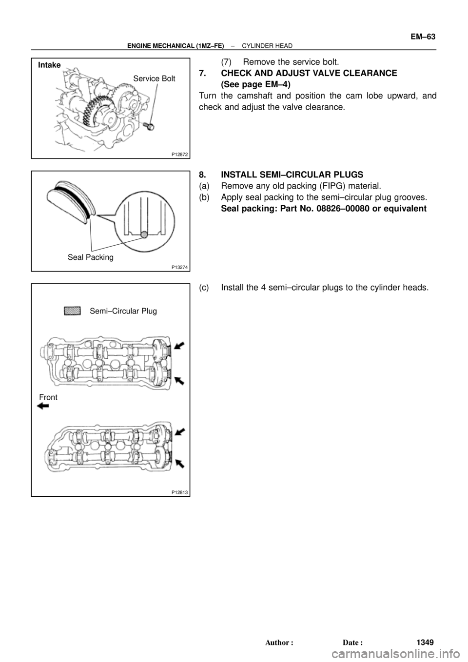
P12872
Service Bolt
Intake
P13274
Seal Packing
P12813
Semi±Circular Plug
Front
± ENGINE MECHANICAL (1MZ±FE)CYLINDER HEAD
EM±63
1349 Author�: Date�:
(7) Remove the service bolt.
7. CHECK AND ADJUST VALVE CLEARANCE
(See page EM±4)
Turn the camshaft and position the cam lobe upward, and
check and adjust the valve clearance.
8. INSTALL SEMI±CIRCULAR PLUGS
(a) Remove any old packing (FIPG) material.
(b) Apply seal packing to the semi±circular plug grooves.
Seal packing: Part No. 08826±00080 or equivalent
(c) Install the 4 semi±circular plugs to the cylinder heads.
Page 3571 of 4770
Except California A/T
S04789
Ground
Strap
Inlet PipeRear
Plate
± ENGINE MECHANICAL (1MZ±FE)CYLINDER HEAD
EM±65
1351")
P12710
New O±Ring
A01522
Manifold
Stay California A/T
Manifold Stay
(Except M/T)Except California A/T
S04789
Ground
Strap
Inlet PipeRear
Plate
± ENGINE MECHANICAL (1MZ±FE)CYLINDER HEAD
EM±65
1351 Author�: Date�:
13. INSTALL OIL DIPSTICK AND GUIDE
(a) Install a new O±ring to the dipstick guide.
(b) Apply soapy water to the O±ring.
(c) Push in the dipstick guide end into the guide hole of the
No.1 oil pan.
(d) Install the dipstick guide with the bolt.
Torque: 8 N´m (80 kgf´cm, 69 in.´lbf)
(e) Install the dipstick.
14. INSTALL CAMSHAFT POSITION SENSOR
15. INSTALL LH EXHAUST MANIFOLD
(a) Install a new gasket and the exhaust manifold with the 6
nuts. Uniformly tighten the nuts in several passes.
Torque: 49 N´m (500 kgf´cm, 36 ft´lbf)
(b) Except M/T:
Install the exhaust manifold stay with the bolt and nut. Al-
ternately tighten the bolt and nut.
Torque:
California A/T:
34 N´m (350 kgf´cm, 25 ft´lbf)
Except California A/T:
20 N´m (200 kgf´cm, 15 ft´lbf)
(c) California:
Connect the A/F sensor connector.
(d) Except California:
Connect the heated oxygen sensor (bank 2 sensor 1)
connector.
16. INSTALL WATER INLET PIPE
(a) Install a new O±ring to the water inlet pipe.
(b) Apply soapy water to the O±ring.
(c) Connect the water inlet pipe to the water inlet.
(d) Install the bolt holding the water inlet pipe to the cylinder
head.
Torque: 19.5 N´m (200 kgf´cm, 14 ft´lbf)
17. INSTALL CYLINDER HEAD REAR PLATE
Torque: 8 N´m (80 kgf´cm, 69 in.´lbf)
18. INSTALL ENGINE WIRE PROTECTOR
19. INSTALL NO.3 TIMING BELT COVER
(a) Check that the timing belt cover gaskets have no cracks
or peeling, etc.
If the gaskets have cracks or peeling etc., replace them using
these steps:
�Using a screwdriver and gasket scraper, remove all
the old gasket material.
�Thoroughly clean all components to remove all the
loose material.
Page 3574 of 4770
EM±68
± ENGINE MECHANICAL (1MZ±FE)CYLINDER HEAD
1354 Author�: Date�:
(w) Connect the DLC1 to the bracket on the intake air control
valve.
(x) Connect the accelerator cable.
(y) Connect the A/T throttle cable.
31. INSTALL HIGH±TENSION CORD SET
32. INSTALL V±BANK COVER
33. INSTALL RH ENGINE MOUNTING STAY
(See page EM±76)
34. INSTALL AIR FILTER AND AIR CLEANER CAP
ASSEMBLY
35. INSTALL RH FENDER APRON SEAL
36. INSTALL FRONT EXHAUST PIPE
(See page EM±76)
37. FILL WITH ENGINE COOLANT
38. START ENGINE AND CHECK FOR LEAKS
39. VEHICLE ROAD TEST
Check for abnormal noise, shock, slippage, correct shift points
and smoothly operation.
40. RECHECK ENGINE COOLANT LEVEL

(3)
(2)
(1)
P12476
SST
A05246
EM±56
± ENGINE MECHANICAL (1MZ±FE)CYLINDER HEAD
1342 Autho")