Page 3604 of 4770
CYLINDER BLOCK
1384 Author�: Date�:
(b) Using a micrometer, measure the piston pin diameter.
Piston pin diameter:
21.997 ± 22.006 mm (")
EM0227
EM6347
P12406
P12493
EM±98
± ENGINE MECHANICAL (1MZ±FE)CYLINDER BLOCK
1384 Author�: Date�:
(b) Using a micrometer, measure the piston pin diameter.
Piston pin diameter:
21.997 ± 22.006 mm (0.8660 ± 0.8664 in.)
(c) Subtract the piston pin diameter measurement from the
bushing inside diameter measurement.
Standard oil clearance:
0.005 ± 0.011 mm (0.0002 ± 0.0004 in.)
Maximum oil clearance: 0.05 mm (0.0020 in.)
15. INSPECT CONNECTING ROD BOLTS
Using vernier calipers, measure the tension portion diameter of
the bolt.
Standard diameter: 7.2 ± 7.3 mm (0.284 ± 0.287 in.)
Minimum diameter: 7.0 mm (0.276 in.)
If the diameter is less than minimum, replace the bolt.
16. INSPECT CRANKSHAFT FOR CIRCLE RUNOUT
(a) Place the crankshaft on V±blocks.
(b) Using a dial indicator, measure the circle runout, as
shown in the illustration.
Maximum circle runout: 0.06 mm (0.0024 in.)
If the circle runout is greater than maximum, replace the crank-
shaft.
17. INSPECT MAIN JOURNALS AND CRANK PINS
(a) Using a micrometer, measure the diameter of each main
journal and crank pin.
Main journal diameter:
60.988 ± 61.000 mm (2.4011 ± 2.4016 in.)
Crank pin diameter:
52.992 ± 53.000 mm (2.0862 ± 2.0866 in.)
If the diameter is not as specified, check the oil clearance.
(See page EM±83)
If necessary, replace the crankshaft.
(b) Check each main journal and crank pin for taper and out±
of±round as shown.
Maximum taper and out±of±round:
0.02 mm (0.0008 in.)
If the taper and out±of±round is greater than maximum, replace
the crankshaft.
Page 3605 of 4770
EM0YT±01
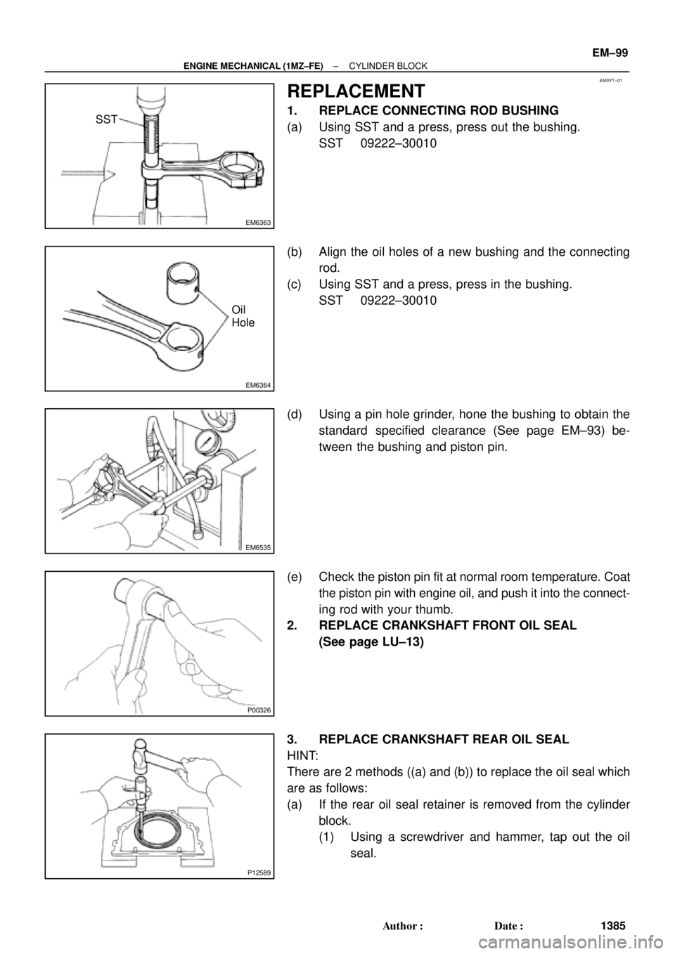
EM6363
SST
EM6364
Oil
Hole
EM6535
P00326
P12589
± ENGINE MECHANICAL (1MZ±FE)CYLINDER BLOCK
EM±99
1385 Author�: Date�:
REPLACEMENT
1. REPLACE CONNECTING ROD BUSHING
(a) Using SST and a press, press out the bushing.
SST 09222±30010
(b) Align the oil holes of a new bushing and the connecting
rod.
(c) Using SST and a press, press in the bushing.
SST 09222±30010
(d) Using a pin hole grinder, hone the bushing to obtain the
standard specified clearance (See page EM±93) be-
tween the bushing and piston pin.
(e) Check the piston pin fit at normal room temperature. Coat
the piston pin with engine oil, and push it into the connect-
ing rod with your thumb.
2. REPLACE CRANKSHAFT FRONT OIL SEAL
(See page LU±13)
3. REPLACE CRANKSHAFT REAR OIL SEAL
HINT:
There are 2 methods ((a) and (b)) to replace the oil seal which
are as follows:
(a) If the rear oil seal retainer is removed from the cylinder
block.
(1) Using a screwdriver and hammer, tap out the oil
seal.
Page 3611 of 4770
CYLINDER BLOCK
EM±105
1391 Author�: Date�:
(a) Apply a light coat of eng")
P12753
10 11
12 13
14
151
162
3
45
6
7
89
P25741
Painted Mark
Front90°
90°
P12586
1
2
34
567
8
± ENGINE MECHANICAL (1MZ±FE)CYLINDER BLOCK
EM±105
1391 Author�: Date�:
(a) Apply a light coat of engine oil on the threads and under
the main bearing cap bolts.
(b) Install and uniformly tighten the 16 main bearing cap
bolts, in several passes, in the sequence shown.
Torque: 22 N´m (225 kgf´cm, 16 ft´lbf)
If any of the main bearing cap bolts does not meet the torque
specification, replace the main bearing cap bolt.
(c) Mark the front of the main bearing cap bolts with paint.
(d) Retighten the main bearing cap bolts by 90° in the numer-
ical order shown.
(e) Check that the painted mark is now at a 90° angle to the
front.
9. INSTALL HEXAGON HEAD MAIN BEARING CAP
BOLTS
(a) Install a new seal washer to the main bearing cap bolt.
(b) Install and uniformly tighten the 8 main bearing cap bolts,
in several passes, in the sequence shown.
Torque: 27 N´m (275 kgf´cm, 20 ft´lbf)
(c) Check that the crankshaft turns smoothly.
10. CHECK CRANKSHAFT THRUST CLEARANCE
(See page EM±83)
Page 3612 of 4770

Front Mark
(1 cavity)Front
Front
Front
FrontRH Piston
LH Piston Front Mark
(1 cavity)
Front Mark
(1 cavity)
P12699
P12801
Front")
S06045
AISIN Made
MAHLE MadeRH Piston
LH Piston Front Mark
(2 Cavities)
Front Mark
(1 cavity)Front
Front
Front
FrontRH Piston
LH Piston Front Mark
(1 cavity)
Front Mark
(1 cavity)
P12699
P12801
Front
Protrusion EM±106
± ENGINE MECHANICAL (1MZ±FE)CYLINDER BLOCK
1392 Author�: Date�:
11. INSTALL PISTON AND CONNECTING ROD
ASSEMBLES
Using a piston ring compressor, push the correctly numbered
piston and connecting rod assemblies into each cylinder with
the front mark of the piston facing forward.
HINT:
The shape of the piston varies for the RH and LH banks. The
RH piston is marked with ºRº, the LH piston with ºLº.
12. PLACE CONNECTING ROD CAP ON CONNECTING
ROD
(a) Match the numbered connecting rod cap with the con-
necting rod.
(b) Align the pin dowels of the connecting rod cap with the
pins of the connecting rod, and install the connecting rod.
(c) Check that the protrusion of the connecting rod cap is fac-
ing in the correct direction.
13. INSTALL CONNECTING ROD CAP BOLTS
HINT:
�The connecting rod cap bolts are tightened in 2 progres-
sive steps (steps (b) and (d)).
�If any of the connecting rod cap bolts is broken or de-
formed, replace it.
Page 3613 of 4770
CYLINDER BLOCK
EM±107
1393 Author�: Date�:
(a) Apply a light coat of engine oil on the threa")
P12697
P25743
Painted Mark
Front90°
90°
P12911
Seal Width
2 ± 3 mm A
BA
B
± ENGINE MECHANICAL (1MZ±FE)CYLINDER BLOCK
EM±107
1393 Author�: Date�:
(a) Apply a light coat of engine oil on the threads and under
the heads of the connecting rod cap bolts.
(b) Install and alternately tighten the 2 connecting rod cap
bolts in several passes.
Torque: 24.5 N´m (250 kgf´cm, 18 ft´lbf)
If any of the connecting rod cap bolts does not meet the torque
specification, replace the connecting rod cap bolts.
(c) Mark the front of the connecting cap bolts with paint.
(d) Retighten the cap bolts by 90° as shown.
(e) Check that the painted mark is now at a 90° angle to the
front.
(f) Check that the crankshaft turns smoothly.
14. CHECK CONNECTING ROD THRUST
CLEARANCE (See page EM±83)
15. INSTALL REAR OIL SEAL RETAINER
(a) Remove any old packing (FIPG) material and be careful
not to drop any oil on the contact surfaces of the oil seal
retainer and cylinder block.
�Using a razor blade and gasket scraper, remove all
the oil packing (FIPG) material from the gasket sur-
faces and sealing grooves.
�Thoroughly clean all components to remove all the
loose material.
�Using a non±residue solvent, clean both sealing
surfaces.
(b) Apply seal packing to the oil seal retainer as shown in the
illustration.
Seal packing: Part No. 08826±00080 or equivalent
�Install a nozzle that has been cut to a 2 ± 3 mm (0.08
± 0.12 in.) opening.
�Parts must be assembled within 3 minutes of ap-
plication. Otherwise the material must be removed
and reapplied.
�Immediately remove nozzle from the tube and rein-
stall cap.
(c) Install the oil seal retainer with the 6 bolts Uniformly tight-
en the bolt in several passes, in the sequence shown.
Torque: 8 N´m (80 kgf´cm, 69 in.´lbf)
16. INSTALL EGR COOLER
Install a new gasket and the EGR cooler with the 3 bolts and 2
nuts.
Torque: 9 N´m (90 kgf´cm, 78 in.´lbf)
Page 3646 of 4770

ADJUSTMENT
ADJUST HEADLIGHT AIM ONLY
(a) Place")
BE20X±01
I21909
For Adjustment
in Vertical Direction
BE±28
± BODY ELECTRICALHEADLIGHT AND TAILLIGHT SYSTEM
2238 Author�: Date�:
2001 CAMRY (RM819U)
ADJUSTMENT
ADJUST HEADLIGHT AIM ONLY
(a) Place the vehicle in the following conditions.
�The area around the headlight is not deformed.
�The vehicle is parked on a level surface.
�Tire inflation pressure is the specified value.
�A driver is in the driver's seat and the vehicle is in a state ready for driving (with a tank full).
�The vehicle has been bounced several times.
(b) Check the headlight aiming.
(1) Prepare a thick white paper.
(2) Stand the paper perpendicular to the ground at the position 9.84 ft away from the headlights.
(3) Ensure that the center line of the vehicle and the paper face forms a 90±degree angle as shown
in the illustration.
(4) Draw a horizontal line (H line) on the paper, showing where the headlights should strike.
(5) Draw a vertical line (V line) to where the center line of the vehicle is to be.
(6) Draw 2 vertical lines to where the the headlights should strike (V RH and V LH lines).
(7) Draw a horizontal line (by connecting the both low beam center marks) to where the headlights
should strike (H RH and H LH lines).
HINT:
The H RH and H LH line is 0.4° below the horizontal line (H line) of the light axis.
(8) Start the engine.
Page 3648 of 4770

IG0DB±01
SPARK TEST
CHECK CONNECTION OF IGNITION COIL WITH
CHECK RESISTANCE OF HIGH±TENSION CORDS
CHECK POWER SUPPLY TO IGNITION COILS WITH
1. Turn ignition switch to ON.
2. Check that there is battery positive voltage at ignition
CHECK RESISTANCE OF IGNITION COILS
Resistance:
SecondaryCold Hot
9.7 ± 16.7 kW12.4 ± 19.6 kW
CHECK RESISTANCE OF SENSORS
Resistance: Cold Hot
Camshaft position sensor
Crankshaft position sensor835 ± 1,400 W
985 ± 1,600 W1,060 ± 1,645 W
1,265 ± 1,890 W
CHECK IGT SIGNAL FROM ECM
TRY ANOTHER IGNITERIGNITER CONNECTORS
(See step 2)
Maximum resistance: 25 kW per cord
IGNITERS
coil positive (+) terminal.
(See step 4)
(See steps 5 and 6)
(See page DI±22) NO
OK
OK
OK
OK
OK
BAD
BAD
BAD
BAD
BAD
BAD
Connect securely.
Replace cord(s).
Check wiring between ignition switch to ignition
Replace ignition coil(s) with igniter(s).
Replace sensor(s).
Check wiring between ECM and igniters, and coils with igniters.
then try another ECM.
± IGNITION (5S±FE)IGNITION SYSTEM
IG±1
1683 Author�: Date�:
IGNITION SYSTEM
ON±VEHICLE INSPECTION
NOTICE:
ºColdº and ºHotº in these sentences express the temperature of the coils themselves. ºColdº is from
±10°C (14°F) to 50°C (122°F) and ºHotº is from 50°C (122°F) to 100°C (212°F).
1. INSPECT SPARK TEST
Check that the spark occurs.
(1) Disconnect the high±tension cord from the spark plug.
(2) Remove the spark plug.
(3) Install the spark plug to the high±tension cord.
(4) Ground the spark plug.
(5) See if spark occurs while engine is being cranked.
NOTICE:
To prevent gasoline from being injected from injectors during this test, crank the engine for no more
than 5 ± 10 seconds at time.
If the spark does not occur, do the test as follows:
Page 3649 of 4770
IGNITION SYSTEM
1684 Author�: Date�:
2. INSPECT HIGH±TENSION CORDS
(a) Remove the high±tension cords.
Disco")
S05295
CORRECT
WRONG
S05542
Ohmmeter
IG0147
Megger
Ground
S03776
IG±2
± IGNITION (5S±FE)IGNITION SYSTEM
1684 Author�: Date�:
2. INSPECT HIGH±TENSION CORDS
(a) Remove the high±tension cords.
Disconnect the high±tension cords at the rubber boot. Do
not pull on the high±tension cords.
NOTICE:
Pulling on or bending the cords may damage the conductor
inside.
(b) Using an ohmmeter, measure the high±tension cord re-
sistance.
Maximum resistance: 25 kW per cord
If the resistance is greater than maximum, check the terminals.
If necessary, replace the high±tension cord.
(c) Reinstall the high±tension cords.
3. INSPECT SPARK PLUGS
NOTICE:
�Never use a wire brush for cleaning.
�Never attempt to adjust the electrode gap on a used
spark plug.
�Spark plugs should be replaced every 100,000 km
(60,000 miles).
(a) Disconnect the high±tension cords from the spark plugs.
(b) Inspect the electrode.
Using a megger (insulation resistance meter), measure
the insulation resistance.
Standard correct insulation resistance:
10 MW or more
If the resistance is less than specified, proceed to step (d).
HINT:
If a megger is not available, the following simple method of in-
spection provides fairly accurate results.
Simple Method:
�Quickly race the engine to 4,000 rpm 5 times.
�Remove the spark plug. (See step (c))
�Visually check the spark plug.
If the electrode is dry ... OK
If the electrode is wet ... Proceed to step (d)
�Reinstall the spark plug. (See step (g))