Page 3724 of 4770
OIL PUMP
1656 Author�: Date�:
INSPECTION
1. INSPECT RELIEF VALVE
Coat the valve with engine oil and check that it falls smoothly
into the v")
LU03M±03
S01170
S01483
S01484
LU±10
± LUBRICATION (5S±FE)OIL PUMP
1656 Author�: Date�:
INSPECTION
1. INSPECT RELIEF VALVE
Coat the valve with engine oil and check that it falls smoothly
into the valve hole by its own weight.
If it doesn't, replace the relief valve. If necessary, replace the oil
pump assembly.
2. INSPECT DRIVE AND DRIVEN ROTORS
(a) Inspect the rotors for body clearance.
Using a feeler gauge, measure the clearance between
the driven rotor and body.
Standard body clearance:
0.10 ± 0.16 mm (0.0039 ± 0.0063 in.)
Maximum body clearance: 0.20 mm (0.0079 in.)
If the body clearance is greater than maximum, replace the ro-
tors as a set. If necessary, replace the oil pump assembly.
(b) Inspect the rotors for tip clearance.
Using a feeler gauge, measure the clearance between
the drive and driven rotor tips.
Standard tip clearance:
0.04 ± 0.16 mm (0.0016 ± 0.0063 in.)
Maximum tip clearance: 0.20 mm (0.0079 in.)
If the tip clearance is greater than maximum, replace the rotors
as a set.
Page 3728 of 4770
LU±14
± LUBRICATION (5S±FE)OIL PUMP
1660 Author�: Date�: �
Immediately remove nozzle from the tube and rein-
stall the cap.
(c) Install the oil pan with the 17 bolts and 2 nuts. Uniformly
tighten the bolts and nuts in several passes.
(d) Install the dipstick.
8. INSTALL NO.2 REAR END PLATE, OIL PAN INSULA-
TOR AND EXHAUST PIPE BRACKET
(See page EM±75)
9. INSTALL LH STIFFENER PLATE AND NO.2 EXHAUST
MANIFOLD STAY (See page EM±23)
10. INSTALL FRONT EXHAUST PIPE
(See page EM±75)
11. FILL WITH ENGINE OIL
12. START ENGINE AND CHECK FOR OIL LEAKS
13. RECHECK ENGINE OIL LEVEL
Page 3732 of 4770
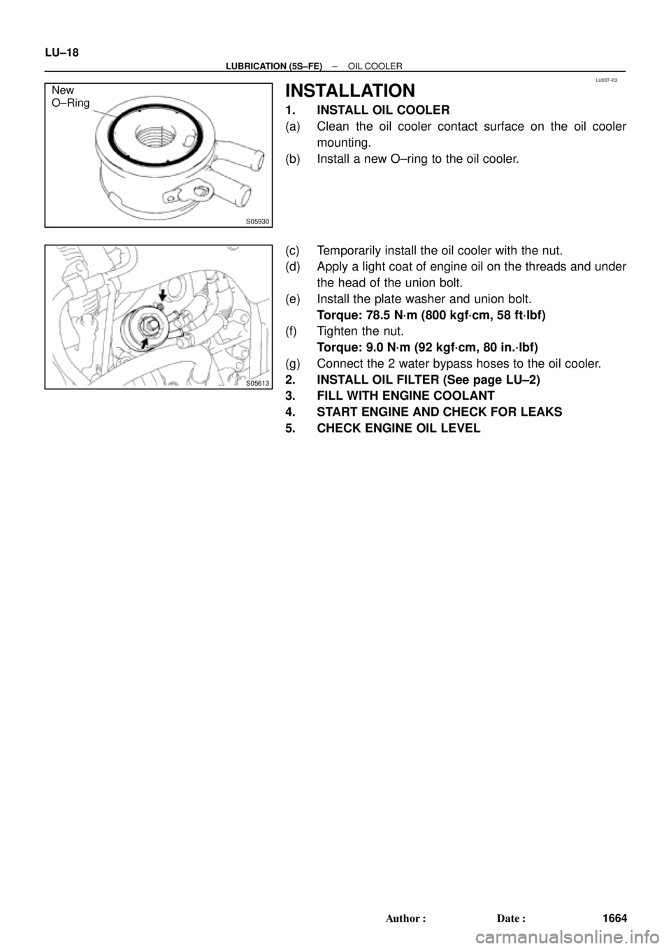
LU03T±03
S05930
New
O±Ring
S05613
LU±18
± LUBRICATION (5S±FE)OIL COOLER
1664 Author�: Date�:
INSTALLATION
1. INSTALL OIL COOLER
(a) Clean the oil cooler contact surface on the oil cooler
mounting.
(b) Install a new O±ring to the oil cooler.
(c) Temporarily install the oil cooler with the nut.
(d) Apply a light coat of engine oil on the threads and under
the head of the union bolt.
(e) Install the plate washer and union bolt.
Torque: 78.5 N´m (800 kgf´cm, 58 ft´lbf)
(f) Tighten the nut.
Torque: 9.0 N´m (92 kgf´cm, 80 in.´lbf)
(g) Connect the 2 water bypass hoses to the oil cooler.
2. INSTALL OIL FILTER (See page LU±2)
3. FILL WITH ENGINE COOLANT
4. START ENGINE AND CHECK FOR LEAKS
5. CHECK ENGINE OIL LEVEL
Page 3733 of 4770
:
TEMPERATURE RANGE ANTICIPATED BEFORE NEXT OIL CHANGE10W±30
5W±30 PREFERRED°C °F
±20
±290
±1820
±740
460
1680
27100
38
LU0FR±01
P25173SST
P25171
Oil Pressur")
B00319
Recommended Viscosity (SAE):
TEMPERATURE RANGE ANTICIPATED BEFORE NEXT OIL CHANGE10W±30
5W±30 PREFERRED°C °F
±20
±290
±1820
±740
460
1680
27100
38
LU0FR±01
P25173SST
P25171
Oil Pressure Gauge
± LUBRICATION (1MZ±FE)OIL AND FILTER
LU±1
1665 Author�: Date�:
OIL AND FILTER
INSPECTION
1. CHECK ENGINE OIL QUALITY
Check the oil for deterioration, entry of water, discoloring or thin-
ning.
If the quality is visibly poor, replace the oil.
Oil grade:
API grade SJ, Energy±Conserving or ILSAC multi-
grade engine oil.
SAE 5W ± 30 is the best choice for your vehicle, for
good fuel economy, and good starting in cold weath-
er.
2. CHECK ENGINE OIL LEVEL
After warm up the engine and then 5 minutes after the engine
stop, oil level should be between the low level and full level
marks on the dipstick.
If low, check for leakage and add oil up to the full level mark.
NOTICE:
Do not fill with engine oil above the full level mark.
3. REMOVE OIL PRESSURE SWITCH, AND INSTALL
OIL PRESSURE GAUGE
(a) Using SST, remove the oil pressure switch.
SST 09816±30010
(b) Install the oil pressure gauge.
4. WARM UP ENGINE
Allow the engine to warm up to normal operating temperature.
5. CHECK OIL PRESSURE
Oil pressure:
At idle29 kPa (0.3 kgf/cm2, 4.3 psi) or more
At 3,000 rpm294 ± 539 kPa (3.0 ± 5.5 kgf/cm2, 43 ± 78 psi)
Page 3734 of 4770
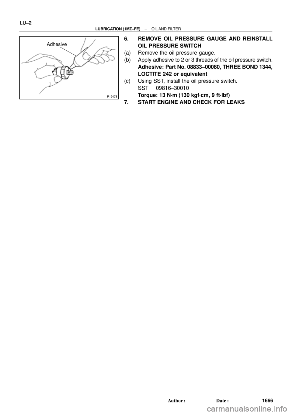
P12478
Adhesive
LU±2
± LUBRICATION (1MZ±FE)OIL AND FILTER
1666 Author�: Date�:
6. REMOVE OIL PRESSURE GAUGE AND REINSTALL
OIL PRESSURE SWITCH
(a) Remove the oil pressure gauge.
(b) Apply adhesive to 2 or 3 threads of the oil pressure switch.
Adhesive: Part No. 08833±00080, THREE BOND 1344,
LOCTITE 242 or equivalent
(c) Using SST, install the oil pressure switch.
SST 09816±30010
Torque: 13 N´m (130 kgf´cm, 9 ft´lbf)
7. START ENGINE AND CHECK FOR LEAKS
Page 3735 of 4770
OIL AND FILTER
LU±3
1667 Author�: Date�:
REPLACEMENT
CAUTION:
�Prolonged and repeated contact with mineral oil wil")
LU026±03
P12486
P12580
SST
P12582
SST
Additional
3/4 Turn
± LUBRICATION (1MZ±FE)OIL AND FILTER
LU±3
1667 Author�: Date�:
REPLACEMENT
CAUTION:
�Prolonged and repeated contact with mineral oil will
result in the removal of natural fats from the skin,
leading to dryness, irritation and dermatitis. In addi-
tion, used engine oil contains potentially harmful
contaminants which may cause skin cancer.
�Exercise caution in order to minimize the length and
frequency of contact of your skin to used oil. Wear
protective clothing and gloves. Wash your skin thor-
oughly with soap and water, or use water±less hand
cleaner, to remove any used engine oil. Do not use
gasoline, thinners, or solvents.
�In order to preserve the environment, used oil and
used oil filter must be disposed of only at designated
disposal sites.
1. DRAIN ENGINE OIL
(a) Remove the oil filler cap.
(b) Remove the oil drain plug, and drain the oil into a contain-
er.
2. REPLACE OIL FILTER
(a) Using SST, remove the oil filter.
SST 09228±07501
(b) Check and clean the oil filter installation surface.
(c) Apply clean engine oil to the gasket of a new oil filter.
(d) Lightly screw the oil filter into place, and tighten it until the
gasket contacts the seat.
(e) Using SST, tighten it an additional 3/4 turn.
SST 09228±07501
Page 3736 of 4770
LU±4
± LUBRICATION (1MZ±FE)OIL AND FILTER
1668 Author�: Date�:
3. REFILL WITH ENGINE OIL
(a) Clean and install the oil drain plug with a new gasket.
Torque: 45 N´m (460 kgf´cm, 33 ft´lbf)
(b) Fill with fresh engine oil.
Capacity:
Drain and refill w/ Oilfilter change
w/o Oilfilter change4.7 liters (5.0 US qts, 4.1 lmp. qts)
4.5 liters (4.8 US qts, 4.0 lmp. qts)
Dry fill5.2 liters (5.5 US qts, 4.6 lmp. qts)
(c) Install the oil filler cap.
4. START ENGINE AND CHECK FOR OIL LEAKS
5. RECHECK ENGINE OIL LEVEL
Page 3744 of 4770
OIL PUMP
1676 Author�: Date�:
INSPECTION
1. INSPECT RELIEF VALVE
Coat the valve with engine oil and check that it falls")
LU02A±03
P12419
P12807
Mark
P12597
P12593
P12592
LU±12
± LUBRICATION (1MZ±FE)OIL PUMP
1676 Author�: Date�:
INSPECTION
1. INSPECT RELIEF VALVE
Coat the valve with engine oil and check that it falls smoothly
into the valve hole by its own weight.
If it does not, replace the relief valve. If necessary, replace the
oil pump assembly.
2. PLACE DRIVE AND DRIVEN ROTORS INTO OIL PUMP
BODY
Place the drive and driven rotors into the oil pump body with the
mark facing upward.
3. INSPECT ROTOR SIDE CLEARANCE
Using a feeler gauge and precision straight edge, measure the
clearance between the rotors and precision straight edge.
Standard side clearance:
0.030 ± 0.090 mm (0.0012 ± 0.0035 in.)
Maximum side clearance: 0.15 mm (0.0059 in.)
If the side clearance is greater than maximum, replace the ro-
tors as a set. If necessary, replace the oil pump assembly.
4. INSPECT ROTOR TIP CLEARANCE
Using a feeler gauge, measure the clearance between the drive
and driven rotor tips.
Standard tip clearance:
0.110 ± 0.240 mm (0.0043 ± 0.0094 in.)
Maximum tip clearance: 0.35 mm (0.0138 in.)
If the tip clearance is greater than maximum, replace the rotors
as a set.
5. INSPECT ROTOR BODY CLEARANCE
Using a feeler gauge, measure the clearance between the driv-
en rotor and body.
Standard body clearance:
0.100 ± 0.175 mm (0.0039 ± 0.0069 in.)
Maximum body clearance: 0.30 mm (0.0118 in.)
If the body clearance is greater than maximum, replace the ro-
tors as a set. If necessary, replace the oil pump assembly.