Page 4064 of 4770
THROTTLE BODY
1463 Author�: Date�:
(b) Connect a TOYOTA hand±held tester or OBDII scan tool.
(1) Remove the fuse cover")
S05331
B01279
Plug
Disconnect
B01280
2.5 mm Hexagon Wrench
SF±30
± SFI (5S±FE)THROTTLE BODY
1463 Author�: Date�:
(b) Connect a TOYOTA hand±held tester or OBDII scan tool.
(1) Remove the fuse cover on the instrument panel.
(2) Connect a TOYOTA hand±held tester or OBDII
scan tool to the DLC3.
(3) Please refer to the TOYOTA hand±held tester or
OBDII scan tool operator's manual for further de-
tails.
(c) Check the idle speed.
Idle speed: 700 ± 50 rpm
(d) Check and adjust the throttle opener setting speed.
(1) Disconnect the vacuum hose from the throttle open-
er, and plug the hose end.
(2) Maintain the engine speed at 2,500 rpm.
(3) Release the throttle valve.
(4) Check that the throttle opener is set.
Throttle opener setting speed:
1,300 ± 1,500 rpm (w/ Cooling fan OFF)
(5) Using a 2.5 mm hexagon wrench, loosen the lock
nut and adjust the throttle opener setting speed by
turning the throttle opener adjusting screw. Tighten
the lock nut.
(6) Reconnect the vacuum hose to the throttle opener.
(e) Disconnect the TOYOTA hand±held tester or OBDII scan
tool.
Page 4069 of 4770
IDLE AIR CONTROL (IAC) VALVE
SF±35
1468 Author�: Date�:
IDLE AIR CONTROL (IAC) VALVE
ON±VEHICLE INSPECTION
1. INSPECT IAC VALVE")
SF0DS±03
A07370
SST
E1
TE1
B01281
Ohmmeter
ISCC+B
ISCO
± SFI (5S±FE)IDLE AIR CONTROL (IAC) VALVE
SF±35
1468 Author�: Date�:
IDLE AIR CONTROL (IAC) VALVE
ON±VEHICLE INSPECTION
1. INSPECT IAC VALVE OPERATION
(a) Initial conditions:
�Engine at normal operating temperature
�Idle speed set correctly
�Transmission in neutral position
(b) Using SST, connect terminals TE1 and E1 of the DLC1.
SST 09843±18020
(c) After the engine speed is kept at 900 ± 1,300 rpm for 5 se-
conds, check that it returns to idle speed.
If the engine speed operation is not as specified, check the IAC
valve, wiring and ECM.
(d) Remove the SST from the DLC1.
SST 09843±18020
2. INSPECT IAC VALVE RESISTANCE
NOTICE:
ºColdº and ºHotº in these sentences express the tempera-
ture of the coils themselves. ºColdº is from ±10°C (14°F) to
50°C (122°F) and ºHotº is from 50°C (122°F) to 100°C
(212°F).
(a) Disconnect the IAC valve connector.
(b) Using an ohmmeter, measure the resistance between ter-
minal +B and other terminals (ISCC, ISCO).
Resistance:
Cold17.0 ± 24.5 W
Hot21.5 ± 28.5 W
If the resistance is not as specified, replace the IAC valve.
(c) Reconnect the IAC valve connector.
Page 4100 of 4770
SF0EN±03
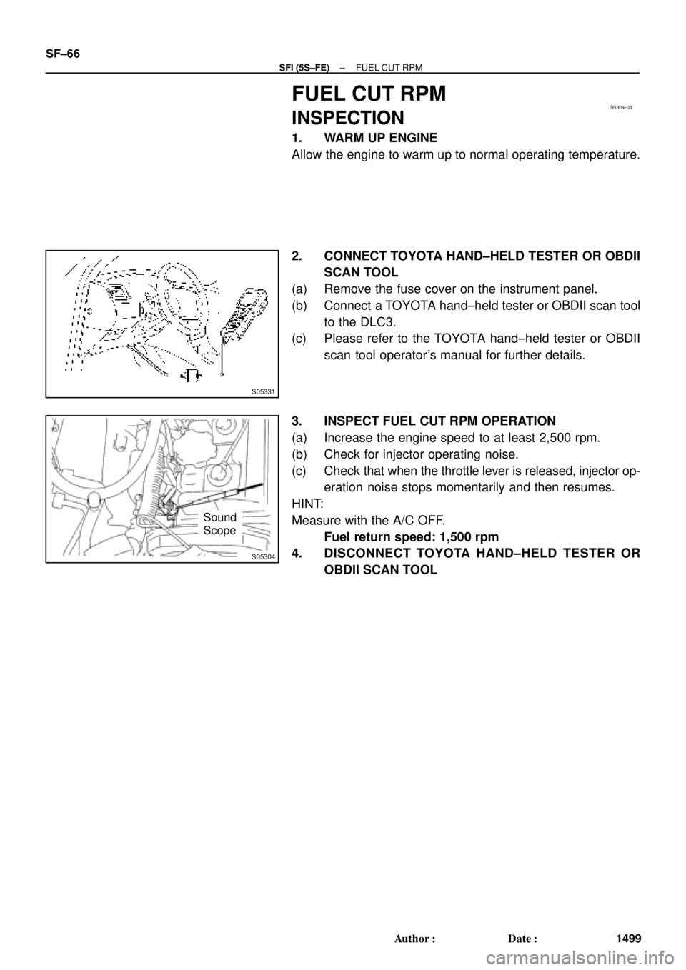
S05331
S05304
Sound
Scope SF±66
± SFI (5S±FE)FUEL CUT RPM
1499 Author�: Date�:
FUEL CUT RPM
INSPECTION
1. WARM UP ENGINE
Allow the engine to warm up to normal operating temperature.
2. CONNECT TOYOTA HAND±HELD TESTER OR OBDII
SCAN TOOL
(a) Remove the fuse cover on the instrument panel.
(b) Connect a TOYOTA hand±held tester or OBDII scan tool
to the DLC3.
(c) Please refer to the TOYOTA hand±held tester or OBDII
scan tool operator's manual for further details.
3. INSPECT FUEL CUT RPM OPERATION
(a) Increase the engine speed to at least 2,500 rpm.
(b) Check for injector operating noise.
(c) Check that when the throttle lever is released, injector op-
eration noise stops momentarily and then resumes.
HINT:
Measure with the A/C OFF.
Fuel return speed: 1,500 rpm
4. DISCONNECT TOYOTA HAND±HELD TESTER OR
OBDII SCAN TOOL
Page 4101 of 4770
SFI SYSTEM
SF±1
1500 Author�: Date�:
SFI SYSTEM
PRECAUTION
1. BEFORE WORKING ON FUEL SYSTEM,
DISCONNECT NEGATIVE (±) TERMINAL CABLE
FROM BATTERY
HINT:
Any diagnostic troub")
SF078±03
± SFI (1MZ±FE)SFI SYSTEM
SF±1
1500 Author�: Date�:
SFI SYSTEM
PRECAUTION
1. BEFORE WORKING ON FUEL SYSTEM,
DISCONNECT NEGATIVE (±) TERMINAL CABLE
FROM BATTERY
HINT:
Any diagnostic trouble code retained by the computer will be
erased when the negative (±) terminal cable is removed from
the battery.
Therefore, if necessary, read the diagnosis before removing the
negative (±) terminal cable from the battery.
2. DO NOT SMOKE OR WORK NEAR AN OPEN FLAME
WHEN WORKING ON FUEL SYSTEM
3. KEEP GASOLINE AWAY FROM RUBBER OR
LEATHER PARTS
4. MAINTENANCE PRECAUTIONS
(a) In event of engine misfire, these precautions should be
taken.
(1) Check proper connection to battery terminals, etc.
(2) After repair work, check that the ignition coil termi-
nals and all other ignition system lines are recon-
nected securely.
(3) When cleaning the engine compartment, be espe-
cially careful to protect the electrical system from
water.
(b) Precautions when handling the oxygen sensor.
(1) Do not allow the oxygen sensor to drop or hit
against an object.
(2) Do not allow the sensor to come into contact with
water.
5. IF VEHICLE IS EQUIPPED WITH A MOBILE RADIO
SYSTEM (HAM, CB, ETC.)
If the vehicle is equipped with a mobile communication system,
refer to the precaution in the IN section.
6. AIR INDUCTION SYSTEM
(a) Separation of the engine oil dipstick, oil filler cap, PCV
hose, etc. may cause the engine to run out of tune.
(b) Disconnection, looseness or cracks in the parts of the air
induction system between the throttle body and cylinder
head will allow air suction and cause the engine to run out
of tune.
7. ELECTRONIC CONTROL SYSTEM
(a) Before removing SFI wiring connectors, terminals, etc.,
first disconnect the power by either turning the ignition
switch to LOCK or disconnecting the negative (±) terminal
cable from the battery.
HINT:
Always check the diagnostic trouble code before disconnecting
the negative (±) terminal cable from the battery.
Page 4102 of 4770
SFI SYSTEM
1501 Author�: Date�:
(b) When installing the battery, be especially careful not to in-
correctly connect the positive")
FI2553
SST
S04600
Fuel
Pump
Connector
S05039
Plug
SF±2
± SFI (1MZ±FE)SFI SYSTEM
1501 Author�: Date�:
(b) When installing the battery, be especially careful not to in-
correctly connect the positive (+) and negative (±) cables.
(c) Do not permit parts to receive a severe impact during re-
moval or installation. Handle all SFI parts carefully, espe-
cially the ECM.
(d) Be careful during troubleshooting as there are numerous
transistor circuit, and even slight terminal contact can
cause further troubles.
(e) Do not open the ECM cover.
(f) When inspecting during rainy weather, take care to pre-
vent entry of water. Also, when washing the engine
compartment, prevent water from getting on the SFI parts
and wiring connectors.
(g) Parts should be replaced as an assembly.
(h) Care should be taken when pulling out and inserting wir-
ing connectors.
(1) Release the lock and pull out the connector, pulling
on the connectors.
(2) Fully insert the connector and check that it is locked.
(i) Use SST for inspection or test of the injector or its wiring
connector.
SST 09842±30070
8. FUEL SYSTEM
(a) When disconnecting the high fuel pressure line, a large
amount of gasoline will spill out, so observe these proce-
dures:
(1) Disconnect the fuel pump connector.
(2) Start the engine. After the engine has stopped on
its own, turn the ignition switch to LOCK.
(3) Put a container under the connection.
(4) Slowly loosen the connection.
(5) Disconnect the connection.
(6) Plug the connection with a rubber plug.
Page 4105 of 4770
SFI SYSTEM
SF±5
1504 Author�: Date�:
(g) Observe these precautions when connecting the fuel
tube connector (quick ty")
S05382
Retainer
S05050
Click Sound
S05358
TOYOTA
Hand±Held Tester
± SFI (1MZ±FE)SFI SYSTEM
SF±5
1504 Author�: Date�:
(g) Observe these precautions when connecting the fuel
tube connector (quick type).
(1) Do not reuse the retainer removed from the pipe.
(2) Must use hands without using tools when to remove
the retainer from the pipe.
(3) Check if there is any damage or foreign objects on
the connected part of the pipe.
(4) Match the axis of the connector with axis of the pipe,
and push in the connector until the retainer makes
a ºclickº sound. In case that the connections is tight,
apply little amount of new engine oil on the tip of the
pipe.
(5) After having finished the connection, check if the
pipe and the connector are securely connected by
pulling them.
(6) Check if there is any fuel leakage.
(h) Observe these precautions when handling nylon tube.
(1) Pay attention not to turn the connected part of the
nylon tube and the quick connector with force when
connecting them.
(2) Pay attention not to kink the nylon tube.
(3) Do not remove the EPDM protector on the outside
of the nylon tube.
(4) Must not close the piping with the nylon tube by
bending it.
(i) Check that there are no fuel leaks after doing mainte-
nance anywhere on the fuel system.
(1) Connect a TOYOTA hand±held tester to the DLC3.
(2) Turn the ignition switch ON and push the TOYOTA
hand±held tester main switch ON.
NOTICE:
Do not start the engine.
(3) Select the active test mode on the TOYOTA hand±
held tester.
(4) Please refer to the TOYOTA hand±held tester oper-
ator 's manual for further details.
(5) If you have no TOYOTA hand±held tester, connect
the positive (+) and negative (±) leads from the bat-
tery to the fuel pump connector.
(See page SF±6)
(6) Check that there are no leaks from any part of the
fuel system.
(7) Turn the ignition switch to LOCK.
(8) Disconnect the TOYOTA hand±held tester from the
DLC3.
Page 4106 of 4770
FUEL PUMP
1505 Author�: Date�:
FUEL PUMP
ON±VEHICLE INSPECTION
1. CHECK FUEL PUMP OPERATION
(a) Connect")
S05358
TOYOTA
Hand Held TesterSF079±04
S05353
S05359
Fuel Tube Connector
SF±6
± SFI (1MZ±FE)FUEL PUMP
1505 Author�: Date�:
FUEL PUMP
ON±VEHICLE INSPECTION
1. CHECK FUEL PUMP OPERATION
(a) Connect a TOYOTA hand±held tester to the DLC3.
(b) Turn the ignition switch ON and push the TOYOTA hand±
held tester main switch ON.
NOTICE:
Do not start the engine.
(c) Select the ACTIVE TEST mode on the TOYOTA hand±
held tester.
(d) Please refer to the TOYOTA hand±held tester operator's
manual for further details.
(e) If you have no TOYOTA hand±held tester, connect the
positive (+) and negative (±) leads from the battery to the
fuel pump connector. (See step 7)
(f) Check that there is pressure in the fuel inlet hose from the
fuel filter.
HINT:
If there is fuel pressure, you will hear the sound of fuel flowing.
If there is no pressure, check these parts:
Fusible link
Fuses
EFI main relay
Fuel pump
ECM
Wiring connections
(g) Turn the ignition switch OFF.
(h) Disconnect the TOYOTA hand±held tester from the
DLC3.
2. CHECK FUEL PRESSURE
(a) Check the battery positive voltage is above 12 V.
(b) Disconnect the negative (±) terminal cable from the bat-
tery.
(c) Purchase the new No.1 fuel pipe and take out the fuel
tube connector from its pipe.
Part No. 23801±20041
Page 4107 of 4770

Pipe
SST
(Hose)SST
± SFI (1MZ±FE)FUEL PUMP
SF±7
1506 Author�: Date�:
(d) Remove the fuel hose clamp.
(e) D")
S06086
Fuel Hose
Clamp
S05352
S05364
SST
SST
Retainer
No.1 Fuel
Fuel Tube
Connector (Hose)
Pipe
SST
(Hose)SST
± SFI (1MZ±FE)FUEL PUMP
SF±7
1506 Author�: Date�:
(d) Remove the fuel hose clamp.
(e) Disconnect the No.1 fuel pipe (fuel tube connector) from
the fuel filter outlet.
CAUTION:
�Perform disconnecting operations of the fuel tube
connector (quick type) after observing the precau-
tions. (See page SF±1)
�As there is retained pressure in the fuel pipe line, pre-
vent it from splashing inside the engine compart-
ment.
(f) Install SST (pressure gauge) as shown in the illustration
by using SST and fuel tube connector.
SST 09268±41047, 09268±41250, 09268±45012
(g) Wipe off any splattered gasoline.
(h) Reconnect the negative (±) terminal cable to the battery.
(i) Connect the TOYOTA hand held tester to the DLC3.
(See step 1. check fuel pump operation (a) to (e))
(j) Measure the fuel pressure.
Fuel pressure:
301 ± 347 kPa (3.1 ± 3.5 kgf/cm
2, 44 ± 50 psi)
If pressure is high, replace the fuel pressure regulator.
If pressure is low, check these parts:
Fuel hoses and connections
Fuel pump
Fuel filter
Fuel pressure regulator
(k) Disconnect the TOYOTA hand±held tester from the
DLC3.
(l) Start the engine.
(m) Measure the fuel pressure at idle.
Fuel pressure:
301 ± 347 kPa (3.1 ± 3.5 kgf/cm
2, 44 ± 50 psi)
(n) Stop the engine.
(o) Check that the fuel pressure remains as specified for 5
minutes after the engine has stopped.
Fuel pressure:
147 kPa (1.5 kgf/cm
2, 21 psi) or more
If pressure is not as specified, check the fuel pump, pressure
regulator and/or injectors.