Page 4293 of 4770
 Visually check the belt for excessive w")
P06717
SR06D±01
Z00038
DENSO Borroughs
P06723
CORRECT WRONG WRONG
± STEERINGDRIVE BELT
SR±3
2098 Author�: Date�:
DRIVE BELT
INSPECTION
INSPECT DRIVE BELT
(a) Visually check the belt for excessive wear, frayed cords
etc.
If any defect has been found, replace the drive belt.
HINT:
Cracks on the rib side of a belt are considered acceptable. If the
belt has chunks missing from the ribs, it should be replaced.
(b) Using a belt tension gauge, measure the belt tension.
Belt tension gauge:
DENSO BTG±20 (95506±00020)
Borroughs No. BT±33±73F
5S±FE Engine:
Drive belt tension:
New belt: 95 ± 145 lbf
Used belt: 60 ± 100 lbf
1MZ±FE Engine:
Drive belt tension:
New belt: 150 ± 185 lbf
Used belt: 95 ± 135 lbf
If the belt tension is not as specified, adjust it.
HINT:
�ºNew beltº refers to a belt which has been used less than
5 minutes on a running engine.
�ºUsed beltº refers to a belt which has been used on a run-
ning engine for 5 minutes or more.
�After installing a belt, check that it fits properly in the
ribbed grooves.
�Check with your hand to confirm that the belt has not
slipped out of the groove on the bottom of the pulley.
�After installing a new belt, run the engine for about 5 min-
utes and recheck the belt tension.
Page 4294 of 4770
SR06E±01
R09599
Normal Abnormal SR±4
± STEERINGPOWER STEERING FLUID
2099 Author�: Date�:
POWER STEERING FLUID
BLEEDING
1. CHECK FLUID LEVEL
(See page SR±5)
2. JACK UP FRONT OF VEHICLE AND SUPPORT IT
WITH STANDS
3. TURN STEERING WHEEL
With the engine stopped, turn the wheel slowly from lock to lock
several times.
4. LOWER VEHICLE
5. START ENGINE
Run the engine at idle for a few minutes.
6. TURN STEERING WHEEL
(a) With the engine idling, turn the wheel to left or right full
lock and keep it there for 2±3 seconds, then turn the
wheel to the opposite full lock and keep it there for 2±3 se-
conds.
(b) Repeat (a) several times.
7. STOP ENGINE
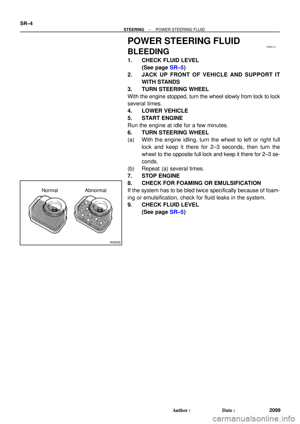
8. CHECK FOR FOAMING OR EMULSIFICATION
If the system has to be bled twice specifically because of foam-
ing or emulsification, check for fluid leaks in the system.
9. CHECK FLUID LEVEL
(See page SR±5)
Page 4295 of 4770

or less
Engine Idling Engine Stopped
± STEERINGPOWER STEERING FLUID
SR±5
2100 Author�: Date�:
INSPECTION
1. CHECK FLUID LEVEL
(a) Keep t")
SR06F±01
R00427
R09599
Normal Abnormal
R11562
5 mm (0.2 in.)
or less
Engine Idling Engine Stopped
± STEERINGPOWER STEERING FLUID
SR±5
2100 Author�: Date�:
INSPECTION
1. CHECK FLUID LEVEL
(a) Keep the vehicle level.
(b) With the engine stopped, check the fluid level in the oil
reservoir.
If necessary, add fluid.
Fluid: ATF DEXRON® II or III
HINT:
Check that the fluid level is within the HOT LEVEL range on the
reservoir. If the fluid is cold, check that it is within the COLD
LEVEL range.
(c) Start the engine and run it at idle.
(d) Turn the steering wheel from lock to lock several times to
boost fluid temperature.
Fluid temperature: 80°C (176°F)
(e) Check for foaming or emulsification.
If there is foaming or emulsification, bleed power steering
system.
(See page SR±4)
(f) With the engine idling, measure the fluid level in the oil
reservoir.
(g) Stop the engine.
(h) Wait a few minutes and remeasure the fluid level in the oil
reservoir.
Maximum fluid level rise: 5 mm (0.20 in.)
If a problem is found, bleed power steering system.
(See page SR±4)
(i) Check the fluid level.
Page 4296 of 4770
W03331
Attachment
Pressure Feed TubePressure Feed Tube SST
Out In 5S±FE Engine : 1MZ±FE Engine :
Out In
AttachmentAttachment Attachment
SST SR±6
± STEERINGPOWER STEERING FLUID
2101 Author�: Date�:
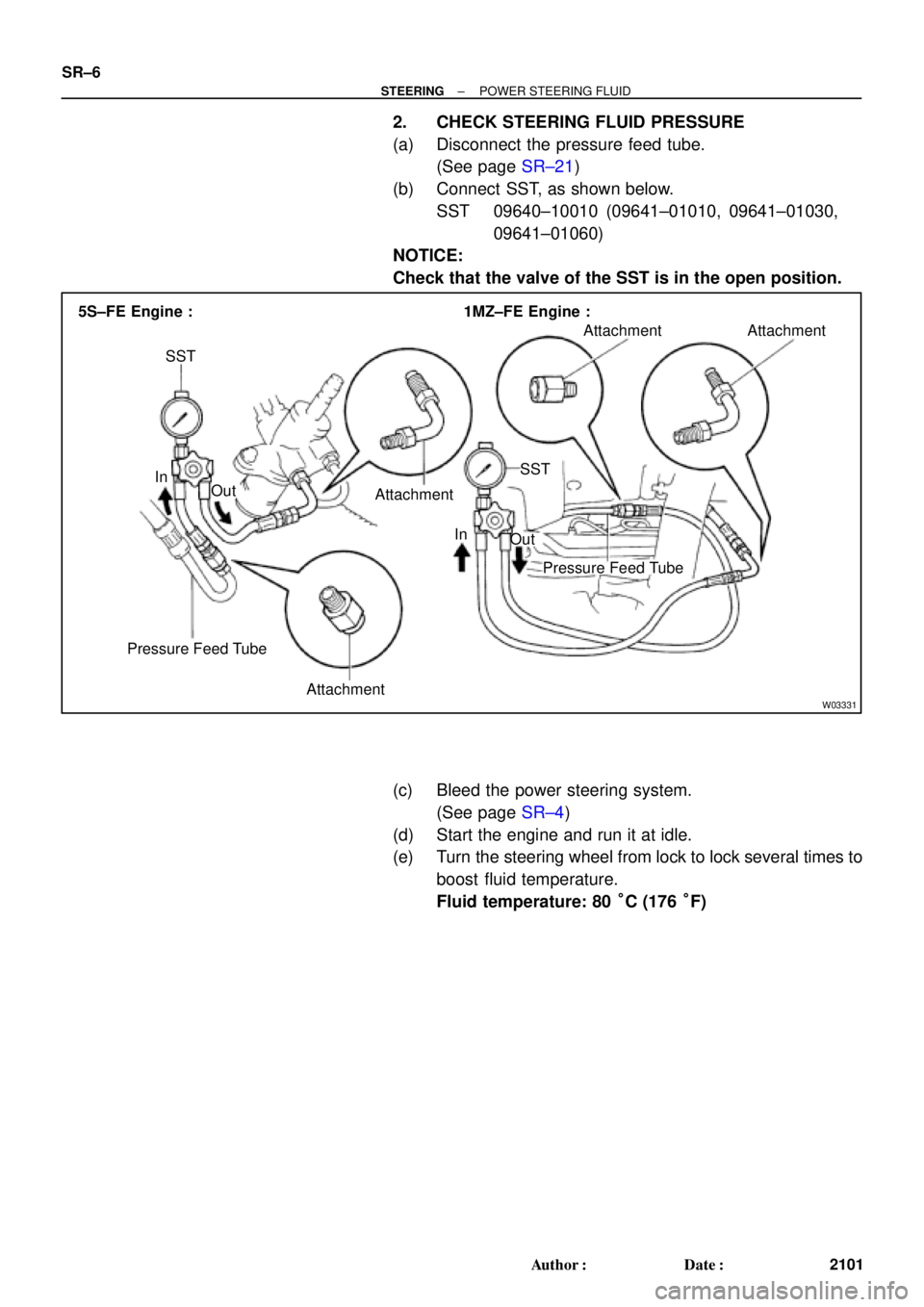
2. CHECK STEERING FLUID PRESSURE
(a) Disconnect the pressure feed tube.
(See page SR±21)
(b) Connect SST, as shown below.
SST 09640±10010 (09641±01010, 09641±01030,
09641±01060)
NOTICE:
Check that the valve of the SST is in the open position.
(c) Bleed the power steering system.
(See page SR±4)
(d) Start the engine and run it at idle.
(e) Turn the steering wheel from lock to lock several times to
boost fluid temperature.
Fluid temperature: 80 °C (176 °F)
Page 4298 of 4770
R07653
SR06G±01
F01477
SR±8
± STEERINGSTEERING WHEEL
2103 Author�: Date�:
STEERING WHEEL
INSPECTION
1. CHECK STEERING WHEEL FREEPLAY
With the vehicle stopped and tires facing straight ahead, rock
the steering wheel gently back and forth with light finger pres-
sure.
Freeplay should not exceed the maximum.
Maximum freeplay: 30 mm (1.18 in.)
2. CHECK STEERING EFFORT
(a) Center the steering wheel.
(b) Remove the steering wheel pad.
(See page SR±11)
(c) Start the engine and run it at idle.
(d) Measure the steering effort in both directions.
Reference: 5.9 N´m (60 kgf´cm, 52 in.´lbf)
HINT:
Be sure to consider the tire type, pressure and contact surface
before making your diagnosis.
(e) Torque the steering wheel set nut.
Torque: 35 N´m (360 kgf´cm, 26 ft´lbf)
(f) Install the steering wheel pad.
(See page SR±16)
Page 4304 of 4770

SR06K±01
W03335
Ignition Key
W03336
SR±14
± STEERINGTILT STEERING COLUMN
2109 Author�: Date�:
INSPECTION
1. INSPECT STEERING LOCK OPERATION
Check that the steering lock mechanism operates properly.
2. IF NECESSARY, REPLACE KEY CYLINDER
(a) Place the ignition key at the ACC position.
(b) Push down the stop pin with a screwdriver, and pull out
the cylinder.
(c) Install a new cylinder.
HINT:
Make sure the key is at the ACC position.
3. INSPECT IGNITION SWITCH
(See page BE±14)
4. IF NECESSARY, REPLACE IGNITION SWITCH
(a) Remove the 2 screws.
(b) Install a new switch with the 2 screws.
5. INSPECT KEY UNLOCK WARNING SWITCH
(See page BE±14)
6. IF NECESSARY, REPLACE KEY UNLOCK WARNING
SWITCH
(a) Slide out the switch.
(b) Install a new switch.
7. A/T:
INSPECT KEY INTERLOCK SOLENOID
(A140E: See page AX±13)
(A541E: See page AX±17)
8. A/T:
IF NECESSARY, REPLACE KEY INTERLOCK SOLE-
NOID
(a) Remove the 2 screws.
(b) Install a new solenoid with the 2 screws.
9. w/ ENGINE IMMOBILISER SYSTEM:
INSPECT TRANSPONDER KEY COIL
(See page BE±128)
10. w/ ENGINE IMMOBILISER SYSTEM:
IF NECESSARY, REPLACE TRANSPONDER KEY
COIL
11. w/ ENGINE IMMOBILISER SYSTEM:
IF NECESSARY, REPLACE TRANSPONDER KEY AM-
PLIFIER
(a) Remove the 2 screws.
(b) Install a new key amplifier with the 2 screws.
Page 4312 of 4770

SR06P±01
W03338
Example 5S±FE Engine :
W03339
Example 5S±FE Engine :
SST SR±22
± STEERINGPOWER STEERING VANE PUMP
2117 Author�: Date�:
DISASSEMBLY
NOTICE:
When using a vise, do not overtighten it.
1. MEASURE PS VANE PUMP ROTATING TORQUE
(a) Check that the pump rotates smoothly without abnormal
noise.
(b) Using a torque wrench, check the pump rotating torque.
5S±FE and 1MZ±FE Engines:
Rotating torque:
0.3 N´m (2.8 kgf´cm, 2.4 in.´lbf) or less
2. REMOVE VANE PUMP PULLEY
Using SST, to stop the pulley rotating, remove the nut.
SST 09960±10010 (09962±01000, 09963±01000)
3. REMOVE FRONT AND REAR BRACKETS
Remove the 3 bolts and 2 nuts.
4. REMOVE SUCTION PORT UNION
(a) Remove the bolt.
(b) Remove the O±ring from the union.
5. REMOVE PRESSURE PORT UNION, FLOW CONTROL
VALVE AND SPRING
Remove the O±ring from the union.
6. REMOVE REAR HOUSING
(a) Remove the 4 bolts.
(b) Remove the 2 O±rings from the housing.
7. REMOVE WAVE WASHER
8. REMOVE SIDE PLATE
9. REMOVE GASKET
10. REMOVE CAM RING, 10 VANE PLATES AND VANE
PUMP ROTOR
Using a screwdriver, remove the snap ring from the vane pump
shaft.
NOTICE:
Take care not to drop the plate.
11. REMOVE VANE PUMP SHAFT
12. REMOVE STRAIGHT PINS
Remove the 2 pins from the front housing.
Page 4313 of 4770

SR06Q±01
R15196
Caliper Gauge
Micrometer
Vane Pump Shaft
Bushing
Front Housing
N00372
Thickness
Height
Length
R10282
Feeler Gauge
± STEERINGPOWER STEERING VANE PUMP
SR±23
2118 Author�: Date�:
INSPECTION
NOTICE:
When using a vise, do not overtighten it.
1. CHECK OIL CLEARANCE BETWEEN VANE PUMP
SHAFT AND BUSHING
Using a micrometer and caliper gauge, measure the oil clear-
ance.
5S±FE and 1MZ±FE Engines:
Standard clearance:
0.03 ± 0.05 mm (0.0012 ± 0.0020 in.)
Maximum clearance: 0.07 mm (0.0028 in.)
If it is more than the maximum, replace the front housing and
vane pump shaft.
2. INSPECT VANE PUMP ROTOR AND VANE PLATES
(a) Using a micrometer, measure the height, thickness and
length of the plates.
5S±FE and 1MZ±FE Engines:
Minimum height: 8.6 mm (0.339 in.)
Minimum thickness: 1.397 mm (0.0550 in.)
Minimum length: 14.991 mm (0.5902 In.)
(b) Using a feeler gauge, measure the clearance between
the rotor groove and plate.
5S±FE and 1MZ±FE Engines:
Maximum clearance: 0.035 mm (0.0014 in.)
If it is more than the maximum, replace the plate and/or rotor
with one having the same mark stamped on the cam ring.