Page 3586 of 4770
EM±80
± ENGINE MECHANICAL (1MZ±FE)ENGINE UNIT
1366 Author�: Date�:
28. INSTALL HOOD
29. FILL ENGINE WITH OIL
30. FILL WITH ENGINE COOLANT
31. START ENGINE AND CHECK FOR LEAKS
32. PERFORM ROAD TEST
Check for abnormal noise, shock, slippage, correct shift points
and smooth operation.
33. RECHECK ENGINE COOLANT AND OIL LEVELS
Page 3590 of 4770
CYLINDER BLOCK
1370 Author�: Date�:
11. REMOVE WATER I")
P18762
P18763
WaterSeal
Plate
Oil Filter
Union
12 mm
Hexagon
Wrench
Coolant
Drain
Union
P12410
P12508
P12695
EM±84
± ENGINE MECHANICAL (1MZ±FE)CYLINDER BLOCK
1370 Author�: Date�:
11. REMOVE WATER INLET HOUSING
(a) Remove the engine wire band.
(b) Disconnect the engine wire clamp from the bracket.
(c) Remove the 8 bolts, 2 nuts and water inlet housing.
12. REMOVE WATER PUMP (See page CO±6)
13. REMOVE NO.2 OIL PAN (See page LU±9)
14. REMOVE OIL STRAINER (See page LU±9)
15. REMOVE NO.1 OIL PAN (See page LU±9)
16. REMOVE OIL PUMP (See page LU±9)
17. REMOVE OIL FILTER (See page LU±9)
18. REMOVE OIL FILTER UNION
Using a 12 mm hexagon wrench, remove the oil filter union.
19. REMOVE WATER SEAL PLATE
Remove the 2 nuts and seal plate.
20. REMOVE ENGINE COOLANT DRAIN UNION
21. REMOVE EGR COOLER
Remove the 3 bolts, 2 nuts, EGR cooler and gasket.
22. REMOVE REAR OIL SEAL RETAINER
(a) Remove the 6 bolts.
(b) Using a screwdriver, remove the oil seal retainer by prying
the portions between the oil seal retainer and main bear-
ing cap.
23. CHECK CONNECTING ROD THRUST CLEARANCE
Using a dial indicator, measure the thrust clearance while mov-
ing the connecting rod back and forth.
Standard thrust clearance:
0.15 ± 0.30 mm (0.0059 ± 0.0118 in.)
Maximum thrust clearance: 0.35 mm (0.0138 in.)
If the thrust clearance is greater than maximum, replace the
connecting rod assembly(s). If necessary, replace the crank-
shaft.
Page 3591 of 4770
P13329
P12707
P12696
P12728
Plastigage
± ENGINE MECHANICAL (1MZ±FE)CYLINDER BLOCK
EM±85
1371 Author�: Date�:
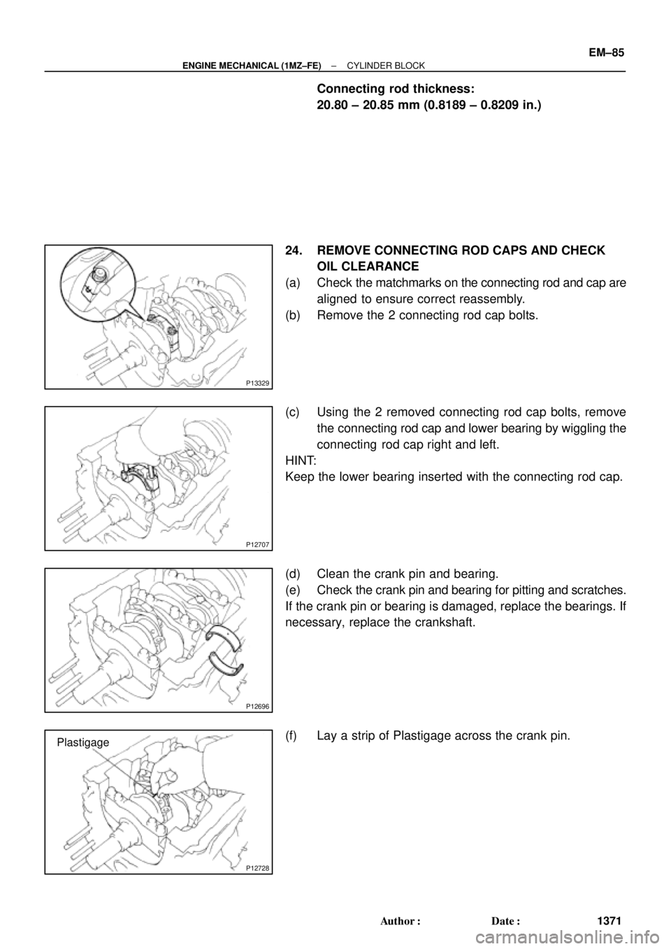
Connecting rod thickness:
20.80 ± 20.85 mm (0.8189 ± 0.8209 in.)
24. REMOVE CONNECTING ROD CAPS AND CHECK
OIL CLEARANCE
(a) Check the matchmarks on the connecting rod and cap are
aligned to ensure correct reassembly.
(b) Remove the 2 connecting rod cap bolts.
(c) Using the 2 removed connecting rod cap bolts, remove
the connecting rod cap and lower bearing by wiggling the
connecting rod cap right and left.
HINT:
Keep the lower bearing inserted with the connecting rod cap.
(d) Clean the crank pin and bearing.
(e) Check the crank pin and bearing for pitting and scratches.
If the crank pin or bearing is damaged, replace the bearings. If
necessary, replace the crankshaft.
(f) Lay a strip of Plastigage across the crank pin.
Page 3593 of 4770
CYLINDER BLOCK
EM±87
1373 Author�: Date�:
26. CHECK CRANKSHAFT THRUST CLEARANCE
Using")
P12799
P12585
P12752
1011 12
1416
15
1 23 4
5
6
7 8
913
P12603
S06200
Joint Surface
± ENGINE MECHANICAL (1MZ±FE)CYLINDER BLOCK
EM±87
1373 Author�: Date�:
26. CHECK CRANKSHAFT THRUST CLEARANCE
Using a dial indicator, measure the thrust clearance while prying
the crankshaft back and forth with a screwdriver.
Standard thrust clearance:
0.04 ± 0.24 mm (0.0016 ± 0.0095 in.)
Maximum thrust clearance: 0.30 mm (0.0118 in.)
If the thrust clearance is greater than maximum, replace the
thrust washers as a set.
Thrust washer thickness:
1.930 ± 1.980 mm (0.0760 ± 0.0780 in.)
27. REMOVE MAIN BEARING CAPS AND CHECK OIL
CLEARANCE
(a) Uniformly loosen and remove the 8 main bearing cap
bolts and seal washers, in the several passes, in the se-
quence shown.
(b) Uniformly loosen and remove the 16 main bearing cap
bolts, in several passes, in the sequence shown.
(c) Using a screwdriver, pry out main bearing caps. Remove
the 4 main bearing caps, lower bearings and (No.2 main
bearing cap only) 2 lower thrust washers.
NOTICE:
Pull up the main bearing cap little by little to the right and
the left by turns and pay attention not to damage the joint
surface of the cylinder block and the main bearing cap.
HINT:
�Keep the lower bearing and main bearing cap together.
�Arrange the main bearing caps and lower thrust washers
in correct order.
Page 3594 of 4770
CYLINDER BLOCK
1374 Author�: Date�:
(d) Lift out the crankshaft.
HINT:
Keep the upper bearings together with the cylinder bl")
P12495
P12980
Plastigage
P12954
P12993
EM±88
± ENGINE MECHANICAL (1MZ±FE)CYLINDER BLOCK
1374 Author�: Date�:
(d) Lift out the crankshaft.
HINT:
Keep the upper bearings together with the cylinder block.
(e) Clean each main journal and bearing.
(f) Check each main journal and bearing for pitting and
scratches.
If the journal or bearing is damaged, replace the bearings. If
necessary, replace the crankshaft.
(g) Place the crankshaft on the cylinder block.
(h) Lay a strip of Plastigage across each journal.
(i) Install the 4 main bearing caps. (See page EM±101)
Torque:
12 pointed head bolts:
1st: 22 N´m (225 kgf´cm, 16 ft´lbf)
2nd: Turn extra 90°
Hexagon head bolts:
27 N´m (275 kgf´cm, 20 ft´lbf)
NOTICE:
Do not turn the crankshaft.
(j) Remove the main bearing caps. (See steps (a) to (c) )
(k) Measure the Plastigage at its widest point.
Standard oil clearance:
No.1 and No.4 journals0.014 ± 0.036 mm (0.0006 ± 0.0014 in.)
No.2 and No.3 journals0.026 ± 0.048 mm (0.0010 ± 0.0019 in.)
Maximum clearance:
No.1 and No.4 journals0.05 mm (0.0020 in.)
No.2 and No.3 journals0.06 mm (0.0024 in.)
If the oil clearance is greater than maximum, replace the bear-
ings. If necessary, replace the crankshaft.
Page 3598 of 4770
P12404
P12405
P12403
P12416
60°C
P12415
EM±92
± ENGINE MECHANICAL (1MZ±FE)CYLINDER BLOCK
1378 Author�: Date�:
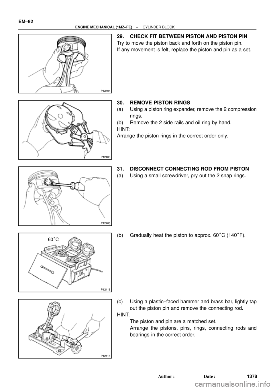
29. CHECK FIT BETWEEN PISTON AND PISTON PIN
Try to move the piston back and forth on the piston pin.
If any movement is felt, replace the piston and pin as a set.
30. REMOVE PISTON RINGS
(a) Using a piston ring expander, remove the 2 compression
rings.
(b) Remove the 2 side rails and oil ring by hand.
HINT:
Arrange the piston rings in the correct order only.
31. DISCONNECT CONNECTING ROD FROM PISTON
(a) Using a small screwdriver, pry out the 2 snap rings.
(b) Gradually heat the piston to approx. 60°C (140°F).
(c) Using a plastic±faced hammer and brass bar, lightly tap
out the piston pin and remove the connecting rod.
HINT:
�The piston and pin are a matched set.
�Arrange the pistons, pins, rings, connecting rods and
bearings in the correct order.
Page 3599 of 4770
EM0YS±01
P12499
Z09222
P12498
± ENGINE MECHANICAL (1MZ±FE)CYLINDER BLOCK
EM±93
1379 Author�: Date�:
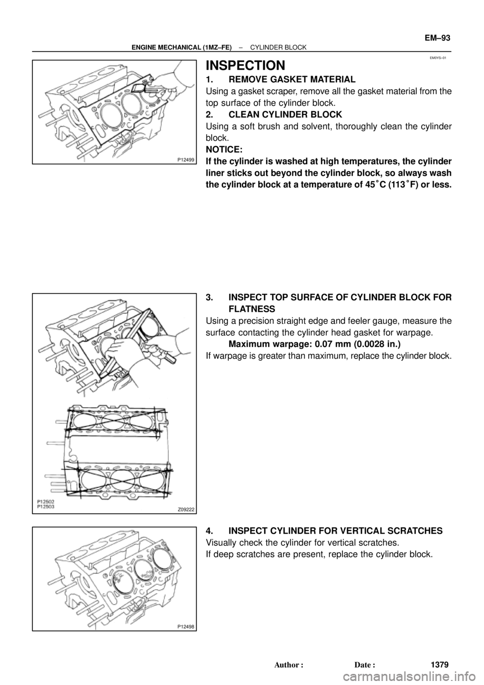
INSPECTION
1. REMOVE GASKET MATERIAL
Using a gasket scraper, remove all the gasket material from the
top surface of the cylinder block.
2. CLEAN CYLINDER BLOCK
Using a soft brush and solvent, thoroughly clean the cylinder
block.
NOTICE:
If the cylinder is washed at high temperatures, the cylinder
liner sticks out beyond the cylinder block, so always wash
the cylinder block at a temperature of 45°C (113°F) or less.
3. INSPECT TOP SURFACE OF CYLINDER BLOCK FOR
FLATNESS
Using a precision straight edge and feeler gauge, measure the
surface contacting the cylinder head gasket for warpage.
Maximum warpage: 0.07 mm (0.0028 in.)
If warpage is greater than maximum, replace the cylinder block.
4. INSPECT CYLINDER FOR VERTICAL SCRATCHES
Visually check the cylinder for vertical scratches.
If deep scratches are present, replace the cylinder block.
Page 3603 of 4770
CYLINDER BLOCK
EM±97
1383 Author�: Date�:
If the end gap is greater than maximum, replace the piston ring.
If the end gap is greater than max")
P12506
Z04012
Z04011
EM6525
± ENGINE MECHANICAL (1MZ±FE)CYLINDER BLOCK
EM±97
1383 Author�: Date�:
If the end gap is greater than maximum, replace the piston ring.
If the end gap is greater than maximum, even with a new piston
ring, replace the cylinder block.
12. INSPECT PISTON PIN FIT
At 60°C (140°F), you should be able to push the piston pin into
the piston pin hole with your thumb.
13. INSPECT CONNECTING ROD ALIGNMENT
Using a rod aligner and feeler gauge, check the connecting rod
alignment.
�Check for out±of±alignment.
Maximum out±of±alignment:
0.05 mm (0.0020 in.) per 100 mm (3.94 in.)
If bend is greater than maximum, replace the connecting rod as-
sembly.
�Check for twist
Maximum twist:
0.15 mm (0.0059 in.) per 100 mm (3.94 in.)
If twist is greater than maximum, replace the connecting rod as-
sembly.
14. INSPECT PISTON PIN OIL CLEARANCE
(a) Using a caliper gauge, measure the inside diameter of the
connecting rod bushing.
Bushing inside diameter:
22.005 ± 22.014 mm (0.8663 ± 0.8667 in.)