Page 3494 of 4770

EM±102
± ENGINE MECHANICAL (5S±FE)CYLINDER BLOCK
1274 Author�: Date�:
(2) Using a micrometer, measure the piston pin diame-
ter.
Piston pin diameter:
21.997 ±")
EM0227
P13428
A02826
15 mm
(0.59 in.)
EM±102
± ENGINE MECHANICAL (5S±FE)CYLINDER BLOCK
1274 Author�: Date�:
(2) Using a micrometer, measure the piston pin diame-
ter.
Piston pin diameter:
21.997 ± 22.009 mm (0.8660 ± 0.8665 in.)
(3) Subtract the piston pin diameter measurement from
the bushing inside diameter measurement.
Standard oil clearance:
0.005 ± 0.011 mm (0.0002 ± 0.0004 in.)
Maximum oil clearance: 0.05 mm (0.0020 in.)
If the oil clearance is greater than maximum, replace the bush-
ing. (See page EM±104) If necessary, replace the piston and
piston pin as a set.
(g) Inspect the connecting rod bolts.
(1) Install the cap nut to the connecting rod bolt. Check
that the cap nut can be turned easily by hand to the
end of the thread.
(2) If the cap nut cannot be turned easily, measure the
outside diameter of the connecting rod bolt with a
vernier caliper.
Standard diameter:
7.860 ± 8.000 mm (0.3094 ± 0.3150 in.)
Minimum diameter: 7.60 mm (0.2992 in.)
HINT:
If the location of this area cannot be judged by visual inspection,
measure the outer diameter at the location shown in the illustra-
tion.
If the outside diameter is less than minimum, replace the con-
necting rod bolt and nut as a set.
Page 3495 of 4770
CYLINDER BLOCK
EM±103
1275 Author�: Date�:
5. INSPECT CRANKSHAFT
(a) Inspect for circle runout.
(1) Place the crankshaft on V±blocks.
(2) Using a dial indi")
P00118
EM3553
± ENGINE MECHANICAL (5S±FE)CYLINDER BLOCK
EM±103
1275 Author�: Date�:
5. INSPECT CRANKSHAFT
(a) Inspect for circle runout.
(1) Place the crankshaft on V±blocks.
(2) Using a dial indicator, measure the circle runout at
the center journal.
Maximum circle runout: 0.06 mm (0.0024 in.)
If the circle runout is greater than maximum, replace the crank-
shaft.
(b) Inspect the main journals and crank pins.
(1) Using a micrometer, measure the diameter of each
main journal and crank pin.
Main journal diameter:
STD54.988 ± 55.003 mm (2.1653 ± 2.1655 in.)
U/S 0.2554.745 ± 54.755 mm (2.1553 ± 2.1557 in.)
Crank pin diameter:
STD51.985 ± 52.000 mm (2.0466 ± 2.0472 in.)
U/S 0.2551.745 ± 51.755 mm (2.0372 ± 2.0376 in.)
If the diameter is not as specified, check the oil clearance. (See
page EM±86) If necessary, grind or replace the crankshaft.
(2) Check each main journal and crank pin for taper
and out±of±round as shown.
Maximum taper and out±of±round:
0.02 mm (0.0008 in.)
If the taper and out±of±round is greater than maximum, replace
the crankshaft.
6. IF NECESSARY, GRIND AND HONE MAIN JOURNALS
AND/OR CRANK PINS
Grind and hone the main journals and/or crank pins to the fin-
ished undersized diameter. (See procedure in step 5) Install
new main journal and/or crankshaft pin undersized bearings.
Page 3496 of 4770
EM08K±03
EM1321
SST
EM7329
Oil Hole
P01038
EM1322
EM±104
± ENGINE MECHANICAL (5S±FE)CYLINDER BLOCK
1276 Author�: Date�:
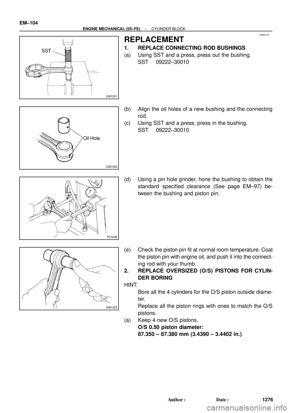
REPLACEMENT
1. REPLACE CONNECTING ROD BUSHINGS
(a) Using SST and a press, press out the bushing.
SST 09222±30010
(b) Align the oil holes of a new bushing and the connecting
rod.
(c) Using SST and a press, press in the bushing.
SST 09222±30010
(d) Using a pin hole grinder, hone the bushing to obtain the
standard specified clearance (See page EM±97) be-
tween the bushing and piston pin.
(e) Check the piston pin fit at normal room temperature. Coat
the piston pin with engine oil, and push it into the connect-
ing rod with your thumb.
2. REPLACE OVERSIZED (O/S) PISTONS FOR CYLIN-
DER BORING
HINT:
�Bore all the 4 cylinders for the O/S piston outside diame-
ter.
�Replace all the piston rings with ones to match the O/S
pistons.
(a) Keep 4 new O/S pistons.
O/S 0.50 piston diameter:
87.350 ± 87.380 mm (3.4390 ± 3.4402 in.)
Page 3501 of 4770
CYLINDER BLOCK
EM±109
1281 Author�: Date�:
(b) Align the bearing claw with the claw groove of the")
P03177
Mark
1, 2, 3, 4, or 5
P05354
P03173
S06012
P00104
1
10
735
84269
± ENGINE MECHANICAL (5S±FE)CYLINDER BLOCK
EM±109
1281 Author�: Date�:
(b) Align the bearing claw with the claw groove of the main
bearing cap, and push in the 5 lower bearings.
HINT:
A number is marked on each main bearing cap to indicate the
installation position.
5. INSTALL UPPER THRUST WASHERS
Install the 2 thrust washers under the No.3 journal position of
the cylinder block with the oil grooves facing outward.
6. PLACE CRANKSHAFT ON CYLINDER BLOCK
7. INSTALL MAIN BEARING CAPS AND LOWER
THRUST WASHERS
(a) Install the 2 thrust washers on the No.3 bearing cap with
the grooves facing outward.
(b) Install the 5 main bearing caps in their proper locations.
HINT:
Each bearing cap has a number and front mark.
(c) Apply a light coat of engine oil on the threads and under
the heads of the main bearing cap bolts.
(d) Install and uniformly tighten the 10 bolts of the main bear-
ing cap in several passes, in the sequence shown.
Torque: 59 N´m (600 kgf´cm, 43 ft´lbf)
(e) Check that the crankshaft turns smoothly.
8. CHECK CRANKSHAFT THRUST CLEARANCE
(See page EM±86)
Page 3503 of 4770
CYLINDER BLOCK
EM±111
1283 Author�: Date�:
(c) Mark the front of")
S02826
Front 90°Painted Mark
90°
S05945
Pulley
Set
Key
Cylinder
Block Top
Surface
P01478
P00716
P00733
± ENGINE MECHANICAL (5S±FE)CYLINDER BLOCK
EM±111
1283 Author�: Date�:
(c) Mark the front of the cap nut with the paint.
(d) Retighten the cap nuts 90° as shown.
(e) Check that the painted mark is now at a 90° angle to the
front.
(f) Check that the crankshaft turns smoothly.
12. CHECK CONNECTING ROD THRUST CLEARANCE
(See page EM±86)
13. INSTALL ENGINE BALANCER
(a) Turn the crankshaft, and set the No.1 cylinder TDC as
shown in the illustration.
(b) Set the balance shafts so that the punch marks of the bal-
ance shafts are aligned with the grooves of the
No.2 housing.
(c) Wipe clean the installation surface of the spacer.
(d) Place the spacers on the cylinder block.
HINT:
When replacing the crankshaft and/or balance shaft, use the
thickest spacers.
(e) Place the engine balancer on the cylinder block.
(f) Check that punch marks shown in the illustration of the
balance shafts are aligned with the grooves of the No.2
housing.
Page 3504 of 4770
CYLINDER BLOCK
1284 Author�: Date�:
(g) While pulling the center part of the engine balancer in the
direction of the arrow,")
S04614
1
Pull 53
426
P01477
Z19357
13
2 EM±112
± ENGINE MECHANICAL (5S±FE)CYLINDER BLOCK
1284 Author�: Date�:
(g) While pulling the center part of the engine balancer in the
direction of the arrow, uniformly tighten the 6 bolts in sev-
eral passes, in the sequence shown.
Torque: 49 N´m (500 kgf´cm, 36 ft´lbf)
(h) Recheck that the punch marks of the balance shafts are
aligned with the grooves of the No.2 housing.
14. CHECK AND ADJUST BACKLASH OF CRANKSHAFT
GEAR AND NO.1 BALANCE SHAFT GEAR
(See page EM±86)
15. INSTALL REAR OIL SEAL RETAINER
Install a new gasket and the retainer with the 6 bolts.
Torque: 13 N´m (130 kgf´cm, 9 ft´lbf)
16. INSTALL WATER PUMP, WATER BYPASS PIPE AND
OIL COOLER (w/ OIL COOLER) ASSEMBLY
(a) Install a new O±ring to the water pump cover.
(b) Install the water pump, water bypass pipe and oil cooler
(w/ oil cooler) assembly with the 3 bolts. Tighten the bolts
in the sequence shown.
Torque: 8.8 N´m (90 kgf´cm, 78 in.´lbf)
(c) Install the generator drive belt adjusting bar with the bolt.
Torque: 22 N´m (224 kgf´cm, 16 ft´lbf)
(d) w/ Oil Cooler:
Install the oil cooler. (See page LU±18)
17. INSTALL OIL FILTER (See page LU±2)
18. INSTALL KNOCK SENSOR 1 (See page SF±57)
19. INSTALL PS PUMP BRACKET
Install the PS pump bracket with the 3 bolts.
Torque: 43 N´m (440 kgf´cm, 32 ft´lbf)
20. INSTALL OIL PUMP AND OIL PAN
(a) Install the oil pump and oil pan. (See page LU±13)
(b) Install the crankshaft position sensor connector to the
generator drive belt adjusting bar.
21. INSTALL OIL DIPSTICK
22. INSTALL CYLINDER HEAD ASSEMBLY
(a) Install the cylinder head assembly. (See page EM±33)
(b) Install the 2 bolts holding the water bypass pipe to the cyl-
inder head.
Torque: 19 N´m (195 kgf´cm, 14 ft´lbf)
(c) Install the VSV for EGR to the cylinder head with the bolt.
(d) Connect the knock sensor 1 connector.
(e) Connect the crankshaft position sensor connector.
Page 3506 of 4770
EM08M±03
A07369
Heated Oxygen Sensor (Bank 1 Sensor 2)
HINT:
Before installing oxygen sensor, twist
sensor wire counterclockwise 3 and 1/2
turns.
After installing oxygen sensor, check that
sensor wire is not twisted. If it is twisted,
remove oxygen sensor and reinstall it.
Heat Insulator
Bracket
RingTailpipe
� Gasket
Center Exhaust Pipe
Heated Oxygen Sensor
(Bank 1 Sensor 2)
TWC (Except California)
Rear TWC (California)
Front Exhaust Pipe Bracket
StayBracket
N´m (kgf´cm, ft´lbf)
� Non±reusable part� Gasket
� Gasket
�Heat Insulator Heat Insulator
Heat Insulator
�
56 (570, 41)
44 (450, 32)
62 (630, 46)
56 (570, 41)
�Bracket
: Specified torqueRing �
�
19 (195, 14)
33 (330, 24)
33 (330, 24)
33 (330, 24)
EM±114
± ENGINE MECHANICAL (5S±FE)EXHAUST SYSTEM
1286 Author�: Date�:
EXHAUST SYSTEM
COMPONENTS
Page 3507 of 4770
CO/HC
EM±1
1287 Author�: Date�:
CO/HC
INSPECTION
HINT:
This check is used only to determine whether or not the idle CO/
HC complies with reg")
EM04I±04
S04994
CO/HC Meter
± ENGINE MECHANICAL (1MZ±FE)CO/HC
EM±1
1287 Author�: Date�:
CO/HC
INSPECTION
HINT:
This check is used only to determine whether or not the idle CO/
HC complies with regulations.
1. INITIAL CONDITIONS
(a) Engine at normal operating temperature
(b) Air cleaner installed
(c) All pipes and hoses of air induction system connected
(d) All accessories switched OFF
(e) All vacuum lines properly connected
HINT:
All vacuum hoses for EGR systems, etc. should be properly
connected.
(f) SFI system wiring connectors fully plugged
(g) Ignition timing check correctly
(h) Transmission in neutral position
(i) Tachometer and CO/HC meter calibrated by hand
2. START ENGINE
3. RACE ENGINE AT 2,500 RPM FOR APPROX. 180
SECONDS
4. INSERT CO/HC METER TESTING PROBE AT LEAST
40 cm (1.3 ft) INTO TAILPIPE DURING IDLING
5. IMMEDIATELY CHECK CO/HC CONCENTRATION
AT IDLE AND/OR 2,500 RPM
HINT:
When doing the 2 mode (idle and 2,500 rpm) test, these mea-
surement order prescribed by the applicable local regulations.

HINT:
Before installing oxygen sensor, twist
sensor wire counterclockwise 3 and 1/2
turns.
After installing oxygen sensor, check that
sensor wir")