Page 4363 of 4770
F00615
R10353
SST
F00616
Clearance
SST
ABC
± SUSPENSION AND AXLEFRONT DRIVE SHAFT (5S±FE)
SA±23
1974 Author�: Date�:
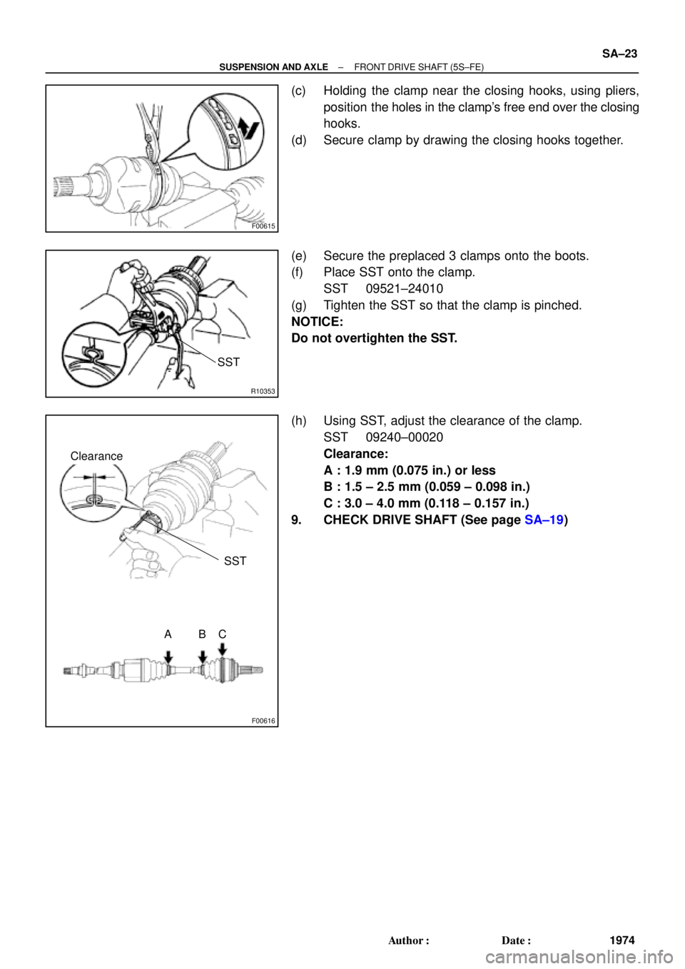
(c) Holding the clamp near the closing hooks, using pliers,
position the holes in the clamp's free end over the closing
hooks.
(d) Secure clamp by drawing the closing hooks together.
(e) Secure the preplaced 3 clamps onto the boots.
(f) Place SST onto the clamp.
SST 09521±24010
(g) Tighten the SST so that the clamp is pinched.
NOTICE:
Do not overtighten the SST.
(h) Using SST, adjust the clearance of the clamp.
SST 09240±00020
Clearance:
A : 1.9 mm (0.075 in.) or less
B : 1.5 ± 2.5 mm (0.059 ± 0.098 in.)
C : 3.0 ± 4.0 mm (0.118 ± 0.157 in.)
9. CHECK DRIVE SHAFT (See page SA±19)
Page 4370 of 4770

1981 Author�: Date�:
4. TEMPORARILY INSTALL OUTBOARD AND INBOARD
JOINT BO")
W03195
Inboard Joint BootOutboard Joint Boot
Vinyl Tape
W03196
R14973
SA±30
± SUSPENSION AND AXLEFRONT DRIVE SHAFT (1MZ±FE)
1981 Author�: Date�:
4. TEMPORARILY INSTALL OUTBOARD AND INBOARD
JOINT BOOTS AND NEW BOOT CLAMPS
HINT:
�Before installing the boots, wrap the spline of the drive
shaft in vinyl tape to prevent the boots from being dam-
aged.
�Before installing the boots, place 3 new clamps to the
small boot ends and large end (wheel side) and then
install boots to drive shaft.
5. INSTALL INBOARD JOINT SHAFT TO OUTBOARD
JOINT SHAFT
Align the matchmarks placed at removal, and using a snap ring
expander, put in the inboard joint shaft expanding the snap ring.
6. INSTALL BOOT TO OUTBOARD JOINT
Before assembling the boot, pack the outboard joint and boot
with grease in the boot kit.
Grease capacity: (Color = Black)
105 ± 125 g (3.7 ± 4.4 oz.)
7. INSTALL BOOT TO INBOARD JOINT SHAFT
(a) Pack the inboard joint and boot with grease in the boot kit.
Grease capacity: (Color = Gray)
Joint side: 142.5 ± 157.5 g (5.0 ± 5.6 oz.)
Boot side: 52.5 ± 57.5 g (2.1 ± 2.3 oz.)
(b) Install the boot to the inboard joint shaft.
8. ASSEMBLE BOOT CLAMPS TO BOTH BOOTS
(a) Make sure that the 2 boots are on the shaft groove.
(b) Make sure that the 2 boots are not stretched or contracted
when the drive shaft is at standard length.
Drive shaft standard length:
M/T LH601.5 ± 2.0 mm (23.681 ± 0.079 in.)
RH871.6 ± 2.0 mm (34.315 ± 0.079 in.)
A/T LH586.0 ± 2.0 mm (23.071 ± 0.079 in.)
RH881.6 ± 2.0 mm (34.709 ± 0.079 in.)
(c) Holding the clamp near the closing hooks, using pliers,
position the holes in the clamp's free end over the closing
hooks.
(d) Secure clamp by drawing the closing hooks together.
Page 4371 of 4770
R10353
SST
F02023
Clearance
SST
ABC
± SUSPENSION AND AXLEFRONT DRIVE SHAFT (1MZ±FE)
SA±31
1982 Author�: Date�:
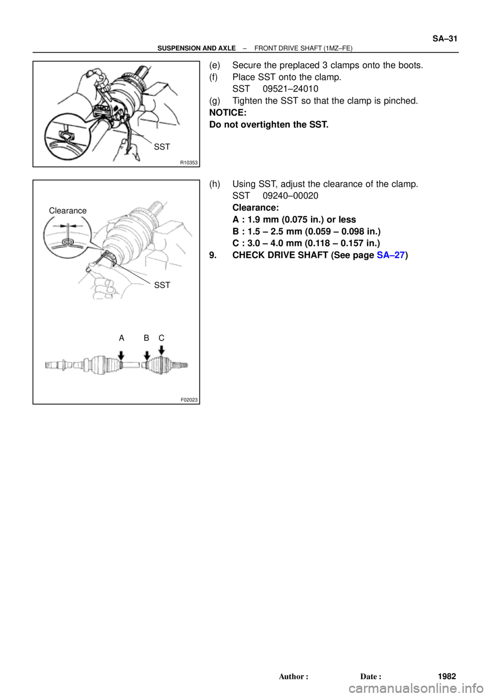
(e) Secure the preplaced 3 clamps onto the boots.
(f) Place SST onto the clamp.
SST 09521±24010
(g) Tighten the SST so that the clamp is pinched.
NOTICE:
Do not overtighten the SST.
(h) Using SST, adjust the clearance of the clamp.
SST 09240±00020
Clearance:
A : 1.9 mm (0.075 in.) or less
B : 1.5 ± 2.5 mm (0.059 ± 0.098 in.)
C : 3.0 ± 4.0 mm (0.118 ± 0.157 in.)
9. CHECK DRIVE SHAFT (See page SA±27)
Page 4375 of 4770
SA07O±01
W03198
SST
SST
W03199
SST
± SUSPENSION AND AXLEFRONT SHOCK ABSORBER
SA±35
1986 Author�: Date�:
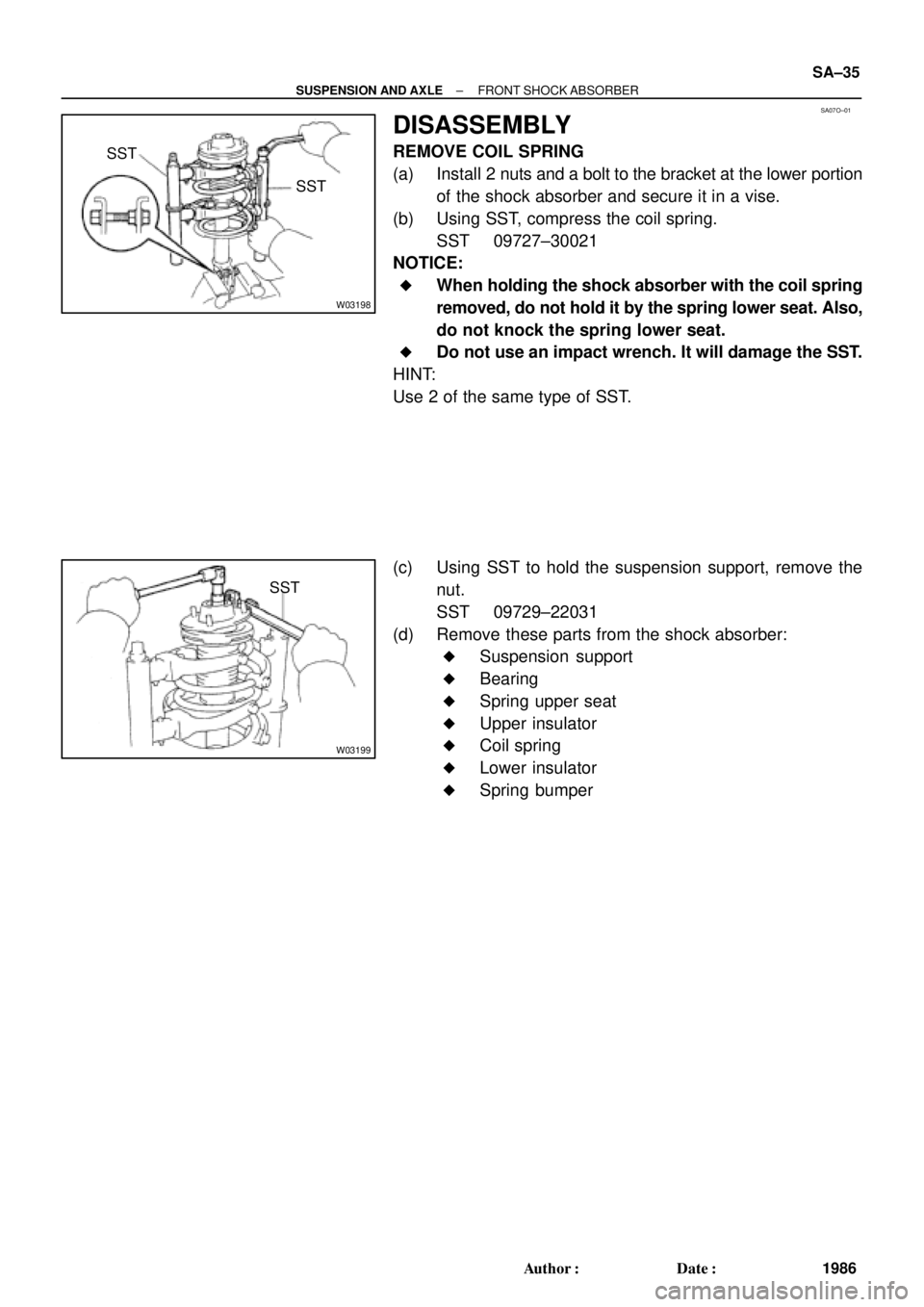
DISASSEMBLY
REMOVE COIL SPRING
(a) Install 2 nuts and a bolt to the bracket at the lower portion
of the shock absorber and secure it in a vise.
(b) Using SST, compress the coil spring.
SST 09727±30021
NOTICE:
�When holding the shock absorber with the coil spring
removed, do not hold it by the spring lower seat. Also,
do not knock the spring lower seat.
�Do not use an impact wrench. It will damage the SST.
HINT:
Use 2 of the same type of SST.
(c) Using SST to hold the suspension support, remove the
nut.
SST 09729±22031
(d) Remove these parts from the shock absorber:
�Suspension support
�Bearing
�Spring upper seat
�Upper insulator
�Coil spring
�Lower insulator
�Spring bumper
Page 4392 of 4770

2. w/ DISC BRAKE:
REMOVE BRAKE CALIPE")
SA086±01
R10948
Z00206
SA±52
± SUSPENSION AND AXLEREAR AXLE HUB
2003 Author�: Date�:
REMOVAL
1. REMOVE REAR WHEEL
Torque: 103 N´m (1,050 kgf´cm, 76 ft´lbf)
2. w/ DISC BRAKE:
REMOVE BRAKE CALIPER AND DISC
(a) Remove the brake caliper and disc.
Torque: 47 N´m (475 kgf´cm, 34 ft´lbf)
(b) Support the brake caliper securely.
3. w/ DRUM BRAKE:
REMOVE BRAKE DRUM
4. CHECK BEARING BACKLASH AND AXLE HUB DEVI-
ATION
(a) Using a dial indicator near the center of the axle hub and
check the backlash in the bearing shaft direction.
Maximum: 0.05 mm (0.0020 in.)
If the backlash exceeds the maximum, replace the axle hub with
the bearing.
(b) Using a dial indicator, check the deviation at the surface
of the axle hub outside the hub bolt.
Maximum: 0.07 mm (0.0028 in.)
If the deviation exceeds the maximum, replace the axle hub
with the bearing.
5. REMOVE REAR AXLE HUB
(a) Remove the 4 bolts and rear axle hub.
Torque: 80 N´m (820 kgf´cm, 59 ft´lbf)
(b) Remove the O±ring.
HINT:
At the time of installation, coat a new O±ring with MP grease.
Page 4393 of 4770
 w/ Drum brake:
Remove the bolt, and disconnect the flexible hose from
the shock absorber.
Torque: 29 N´m (300")
A
B
A
W03211
R11165
± SUSPENSION AND AXLEREAR AXLE HUB
SA±53
2004 Author�: Date�:
(c) w/ Drum brake:
Remove the bolt, and disconnect the flexible hose from
the shock absorber.
Torque: 29 N´m (300 kgf´cm, 22 ft´lbf)
(d) Support the backing plate securely.
6. w/ ABS:
REMOVE ABS SPEED SENSOR
Torque: 8.0 N´m (82 kgf´cm, 71 in.´lbf)
7. REMOVE REAR AXLE CARRIER
(a) Loosen the 3 nuts.
Torque:
Nut A:
Reused nut: 196 N´m (2,000 kgf´cm, 145 ft´lbf)
New nut: 255 N´m (2,600 kgf´cm, 188 ft´lbf)
Nut B: 181 N´m (1,850 kgf´cm, 134 ft´lbf)
HINT:
At the time of installation, please refer to the following items.
�If reusing the 2 nuts, coat the nut's threads with en-
gine oil.
�After stabilizing the suspension, torque the nuts.
(b) Remove the bolt and nut, and disconnect the strut rod
from the rear axle carrier.
NOTICE:
When removing/installing bolt, stop the nut from rotating
and loosen/torque the bolt.
Torque: 113 N´m (1,150 kgf´cm, 83 ft´lbf)
(c) Remove the 2 nuts and bolts on the lower side of the
shock absorber.
(d) Remove the nut, bolt and No.2 lower suspension arm.
(e) Remove the rear axle carrier.
Page 4398 of 4770
SA08B±01
W03214
SST SA±58
± SUSPENSION AND AXLEREAR SHOCK ABSORBER
2009 Author�: Date�:
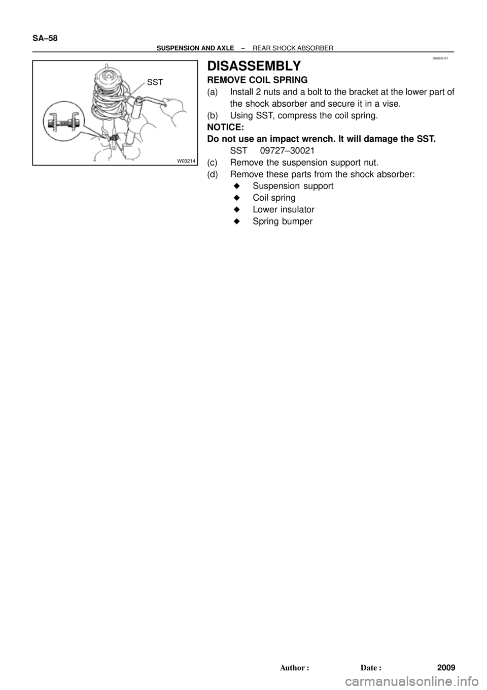
DISASSEMBLY
REMOVE COIL SPRING
(a) Install 2 nuts and a bolt to the bracket at the lower part of
the shock absorber and secure it in a vise.
(b) Using SST, compress the coil spring.
NOTICE:
Do not use an impact wrench. It will damage the SST.
SST 09727±30021
(c) Remove the suspension support nut.
(d) Remove these parts from the shock absorber:
�Suspension support
�Coil spring
�Lower insulator
�Spring bumper
Page 4427 of 4770

Toyota Supports ASE CertificationPage 1 of 4
AX005±99Title:
TOYOTA VIP RS3000 PROGRAMMING
Models:
All Models
Technical Service
BULLETIN
April 9, 1999
This bulletin describes the procedures that are used to program the two±button remote
control for vehicles that are equipped with the dealer or port installed option (PIO), not
the factory security system. For factory security system remote control programming,
refer to the appropriate vehicle repair manual.
Verification of the dealer or PIO Toyota VIP can easily be performed by identifying the
status monitor or remote transmitter.
� The remote transmitter has two
buttons, Top and Bottom.� The status monitor has a Toyota
label, LED, and microphone.
Remote Control Status MonitorLED
Microphone
Starting with 1998 MY, the remote controls for the RS3000 System were revised with new
coding logics. The color of the remote control cases was changed from Black to Gray to
help identify the new remote controls. The new (Gray) remote controls will not work with
the RS3000 ECU's produced prior to 1998 MY. The old (Black) remote controls are still
available for Service Parts.
NOTE:
The TVIP is programmed to operate with the two remote controls that come with the
vehicle. The ECU (computer) can be programmed to operate with up to four different
remote controls. For customer satisfaction, request that any existing remote be
furnished when programming a new or replacement unit.
�All models with dealer or PIO equipped Toyota VIP (RS3000)
CODEDESCRIPTIONTIMEOPNT1T2
N/ANot applicable to warranty ±±±±
ACCESSORIES
Introduction
Affected
Vehicles
Warranty
Information