Page 4221 of 4770

R05403
H0133710 m (33 ft) or more SSTBattery
Side Airbag
Assembly
H00544
RS±46
± SUPPLEMENTAL RESTRAINT SYSTEMSIDE AIRBAG ASSEMBLY (TMC Made)
2191 Author�: Date�:
(e) Place")
H01336
Tires
(5 or More)
R05403
H0133710 m (33 ft) or more SSTBattery
Side Airbag
Assembly
H00544
RS±46
± SUPPLEMENTAL RESTRAINT SYSTEMSIDE AIRBAG ASSEMBLY (TMC Made)
2191 Author�: Date�:
(e) Place the tires.
(1) Place at least 2 tires under the tire to which the side
airbag assembly is tied.
(2) Place at least 2 tires over the tire to which the side
airbag assembly is tied. The top tire should have the
wheel installed.
(3) Tie the tires together with the 2 wire harnesses.
CAUTION:
Make sure that the wire harnesses are tight. It is very dan-
gerous when loose wire harnesses result in the tires com-
ing free due to the shock from the airbag deploying.
HINT:
Place the SST connector and wire harness inside tires. Secure
at least 1 m (3 ft) of slack for the wire harness.
(f) Install the SST.
Connect the connector of 2 SST to the side airbag assem-
bly connector.
SST 09082±00700, 09082±00750
(g) Deploy the airbag.
(1) Connect the SST red clip to the battery positive (+)
terminal and the black clip to the battery negative
(±) terminal.
(2) Check that no one is within 10 m (33 ft) area around
the tire which the side airbag assembly is tied to.
(3) Press the SST activation switch and deploy the air-
bag.
HINT:
The airbag deploys simultaneously as the LED of the SST ac-
tivation switch lights up.
(h) Dispose of the side airbag assembly.
CAUTION:
�The side airbag assembly is very hot when the airbag
is deployed, so leave it alone for at least 30 minutes
after deployment.
�Use gloves and safety glasses when handling a side
airbag assembly with the deployed airbag.
�Do not apply water etc. to a side airbag assembly with
the deployed airbag.
Page 4232 of 4770

RS±57
2202 Author�: Date�:
INSTALLATION
NOTICE:
Never use airbag parts from another vehicle. When replac-
ing parts,")
RS0EX±01
H01871
± SUPPLEMENTAL RESTRAINT SYSTEMSIDE AIRBAG ASSEMBLY (TMMK Made)
RS±57
2202 Author�: Date�:
INSTALLATION
NOTICE:
Never use airbag parts from another vehicle. When replac-
ing parts, replace them with new parts.
1. INSTALL SEATBACK ASSEMBLY
(a) Install the seatback assembly.
(b) Securely fix the side airbag sub wire harness to the seat
cushion with clips.
(c) Connect the side airbag connector of the side airbag as-
sembly side.
(d) Install new hog rings.
HINT:
Install the hog rings to prevent wrinkles as little as possible.
(e) Install the 4 bolts.
2. INSTALL FRONT SEAT CUSHION SHIELD
3. Manual adjuster type:
INSTALL VERTICAL ADJUSTER KNOB
4. Manual adjuster type:
INSTALL RELEASE HANDLE
5. Power adjuster type:
CONNECT CONNECTOR
Connect the connector to the power seat switch.
6. INSTALL FRONT SEAT CUSHION LOWER SHIELD
7. INSTALL HEADREST SUPPORT
8. INSTALL HEADREST
9. INSTALL FRONT SEAT
(a) Slide the front seat to the most front position.
NOTICE:
Make sure that seat adjuster locks.
(b) Without holding the seat track handle, mount the seat to
the vehicle.
HINT:
If holding the seat track handle, the adjusted most front position
will slip off.
(c) Tighten the bolts on the rear side temporarily, starting
from the bolt on the inner side tighten them completely.
Torque: 37 N´m (375 kgf´cm, 27 ft´lbf)
(d) Slide the seat to the rearmost position to install the bolts
on the front side.
Torque: 37 N´m (375 kgf´cm, 27 ft´lbf)
(e) Power adjuster type:
Connect the side airbag connector and power seat con-
nector.
(f) Manual adjuster type:
Connect the side airbag connector.
Page 4234 of 4770
RS0EY±01
H02267H02268H08322
LH side:
RH side:
± SUPPLEMENTAL RESTRAINT SYSTEMAIRBAG SENSOR ASSEMBLY
RS±59
2204 Author�: Date�:
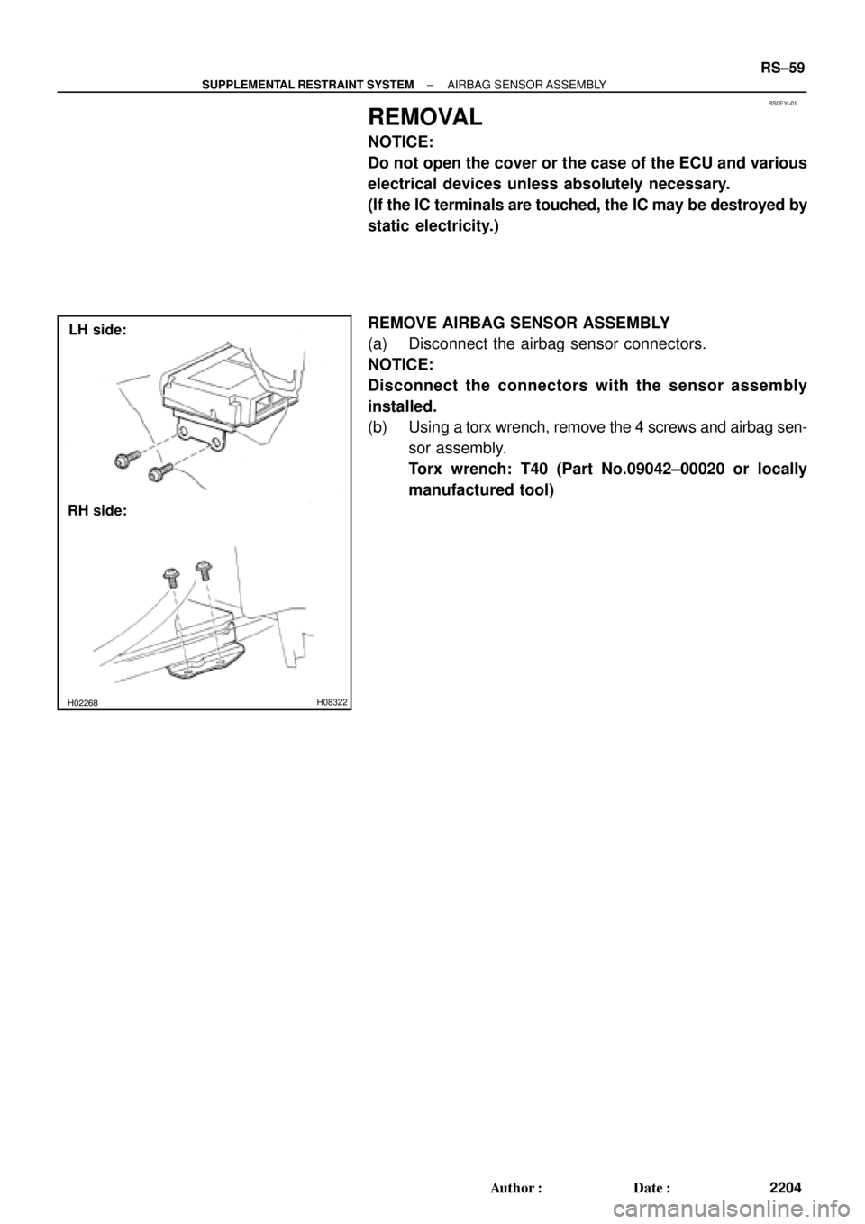
REMOVAL
NOTICE:
Do not open the cover or the case of the ECU and various
electrical devices unless absolutely necessary.
(If the IC terminals are touched, the IC may be destroyed by
static electricity.)
REMOVE AIRBAG SENSOR ASSEMBLY
(a) Disconnect the airbag sensor connectors.
NOTICE:
Disconnect the connectors with the sensor assembly
installed.
(b) Using a torx wrench, remove the 4 screws and airbag sen-
sor assembly.
Torx wrench: T40 (Part No.09042±00020 or locally
manufactured tool)
Page 4242 of 4770
 Install the front airbag sensor with")
RS01P±14
H06728
LH:
RH:
± SUPPLEMENTAL RESTRAINT SYSTEMFRONT AIRBAG SENSOR
RS±67
2212 Author�: Date�:
INSTALLATION
1. INSTALL FRONT AIRBAG SENSOR LH AND RH
(a) Install the front airbag sensor with the arrow on the sensor
facing toward the front of the vehicle.
Torque: 20 N´m (205 kgf´cm, 15 ft´lbf)
NOTICE:
�Connection of the connector is done after the sensor
assembly has been installed.
�Make sure the sensor is installed with the specified
torque.
�If the sensor has been dropped, or there are cracks,
dents or other defects in the case, brackets or con-
nector, replace the removed sensor with a new one.
�The front sensor is equipped with an electrical con-
nection check mechanism. Be sure to lock this mech-
anism securely when connecting the connector. If the
connector is not securely locked, a malfunction code
will be detected by the diagnostic system.
(b) Connect the front airbag sensor connector.
2. INSTALL HEAD LIGHT LH AND RH
(See page BE±28)
3. INSTALL TURN SIGNAL LIGHT LH AND RH
Page 4244 of 4770
RS01R±05
H01346
H01339
± SUPPLEMENTAL RESTRAINT SYSTEMSIDE AIRBAG SENSOR ASSEMBLY
RS±69
2214 Author�: Date�:
REMOVAL
NOTICE:
Do not open the cover or the case of the ECU and various
electrical devices unless absolutely necessary.
(If the IC terminals are touched, the IC may be destroyed by
static electricity.)
1. REMOVE FRONT DOOR SCUFF PLATE
2. REMOVE CENTER PILLAR LOWER GARNISH
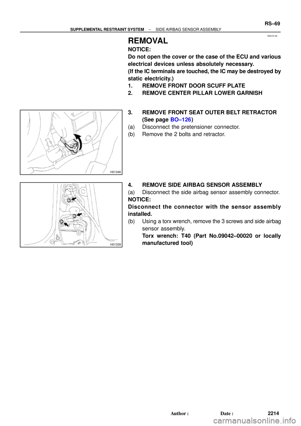
3. REMOVE FRONT SEAT OUTER BELT RETRACTOR
(See page BO±126)
(a) Disconnect the pretensioner connector.
(b) Remove the 2 bolts and retractor.
4. REMOVE SIDE AIRBAG SENSOR ASSEMBLY
(a) Disconnect the side airbag sensor assembly connector.
NOTICE:
Disconnect the connector with the sensor assembly
installed.
(b) Using a torx wrench, remove the 3 screws and side airbag
sensor assembly.
Torx wrench: T40 (Part No.09042±00020 or locally
manufactured tool)
Page 4325 of 4770
SR06V±01
W04228
SST
W04229
SST
R00429
Matchmarks
W04230
R11644
Claw Washer
± STEERINGPOWER STEERING GEAR
SR±35
2130 Author�: Date�:
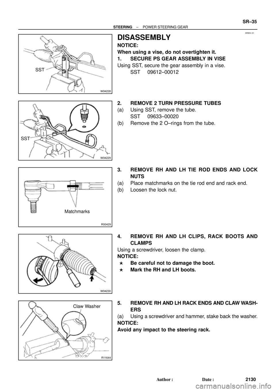
DISASSEMBLY
NOTICE:
When using a vise, do not overtighten it.
1. SECURE PS GEAR ASSEMBLY IN VISE
Using SST, secure the gear assembly in a vise.
SST 09612±00012
2. REMOVE 2 TURN PRESSURE TUBES
(a) Using SST, remove the tube.
SST 09633±00020
(b) Remove the 2 O±rings from the tube.
3. REMOVE RH AND LH TIE ROD ENDS AND LOCK
NUTS
(a) Place matchmarks on the tie rod end and rack end.
(b) Loosen the lock nut.
4. REMOVE RH AND LH CLIPS, RACK BOOTS AND
CLAMPS
Using a screwdriver, loosen the clamp.
NOTICE:
�Be careful not to damage the boot.
�Mark the RH and LH boots.
5. REMOVE RH AND LH RACK ENDS AND CLAW WASH-
ERS
(a) Using a screwdriver and hammer, stake back the washer.
NOTICE:
Avoid any impact to the steering rack.
Page 4350 of 4770

2. CHECK BE")
SA07C±01
W03084W03084
W03093
W03139
W03094
SST
SA±10
± SUSPENSION AND AXLEFRONT AXLE HUB
1961 Author�: Date�:
REMOVAL
1. REMOVE FRONT WHEEL
Torque: 103 N´m (1,050 kgf´cm, 76 ft´lbf)
2. CHECK BEARING BACKLASH AND AXLE HUB DEVI-
ATION
(a) Remove the 2 bolts, brake caliper and disc.
(b) Support the brake caliper securely.
(c) Using a dial indicator near the center of the axle hub and
check the backlash in the bearing shaft direction.
Maximum: 0.05 mm (0.0020 in.)
If the backlash exceeds the maximum, replace the bearing.
(d) Using a dial indicator, check the deviation at the surface
of the axle hub outside the hub bolt.
Maximum: 0.05 mm (0.0020 in.)
If the deviation exceeds the maximum, replace the bearing.
(e) Install the disc, 2 bolts and brake caliper.
Torque: 107 N´m (1,090 kgf´cm, 79 ft´lbf)
3. REMOVE DRIVE SHAFT LOCK NUT
(a) Remove the cotter pin and lock cap.
(b) With applying the brakes, remove the nut.
Torque: 294 N´m (3,000 kgf´cm, 217 ft´lbf)
(c) Remove the brake caliper and disc.
4. w/ ABS:
REMOVE ABS SPEED SENSOR AND WIRE HARNESS
CLAMP
Torque: 8.0 N´m (82 kgf´cm, 71 in.´lbf)
5. LOOSEN 2 NUTS ON LOWER SIDE OF SHOCK AB-
SORBER
Torque: 211 N´m (2,150 kgf´cm, 156 ft´lbf)
HINT:
�Do not remove the bolts.
�At the time of installation, coat the nut's thread with en-
gine oil.
6. DISCONNECT TIE ROD END FROM STEERING
KNUCKLE
(a) Remove the cotter pin and nut.
Torque: 49 N´m (500 kgf´cm, 36 ft´lbf)
(b) Using SST, disconnect the tie rod end from the steering
knuckle.
SST 09610±20012
Page 4355 of 4770
W03096
SST
SA07G±01
W03097
± SUSPENSION AND AXLEFRONT WHEEL HUB BOLT
SA±15
1966 Author�: Date�:
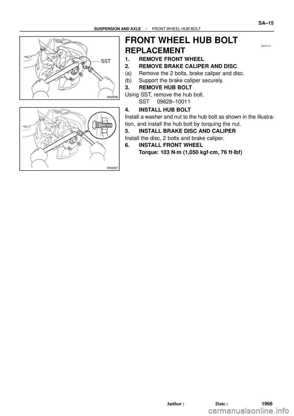
FRONT WHEEL HUB BOLT
REPLACEMENT
1. REMOVE FRONT WHEEL
2. REMOVE BRAKE CALIPER AND DISC
(a) Remove the 2 bolts, brake caliper and disc.
(b) Support the brake caliper securely.
3. REMOVE HUB BOLT
Using SST, remove the hub bolt.
SST 09628±10011
4. INSTALL HUB BOLT
Install a washer and nut to the hub bolt as shown in the illustra-
tion, and install the hub bolt by torquing the nut.
5. INSTALL BRAKE DISC AND CALIPER
Install the disc, 2 bolts and brake caliper.
6. INSTALL FRONT WHEEL
Torque: 103 N´m (1,050 kgf´cm, 76 ft´lbf)