Page 3714 of 4770
± INTRODUCTIONTERMS
IN±43
43 Author�: Date�:
TCMTransmission Control ModuleTransmission ECU, ECT ECU
TPThrottle PositionThrottle Position
TRTransmission Range±
TVVThermal Vacuum ValveBimetallic Vacuum Switching Valve (BVSV)
Thermostatic Vacuum Switching Valve (TVSV)
TWCThree±Way Catalytic Converter
Three±Way Catalytic (TWC)
Manifold Converter
CC
RO
TWC+OCThree±Way + Oxidation Catalytic ConverterCCR + CCo
VA FVolume Air FlowAir Flow Meter
VRVoltage RegulatorVoltage Regulator
VSSVehicle Speed SensorVehicle Speed Sensor
WOTWide Open ThrottleFull Throttle
WU±OCWarm Up Oxidation Catalytic Converter±
WU±TWCWarm Up Three±Way Catalytic Converter±
3GRThird Gear±
4GRFourth Gear±
Page 3751 of 4770

MA001±10
± MAINTENANCEOUTSIDE VEHICLE
MA±1
44 Author�: Date�:
OUTSIDE VEHICLE
GENERAL MAINTENANCE
These are maintenance and inspection items which are considered to be the owner's responsibility.
They can be done by the owner or they can have them done at a service shop.
These items include those which should be checked on a daily basis, those which, in most cases, do not
require (special) tools and those which are considered to be reasonable for the owner to do.
Items and procedures for general maintenance are as follows.
1. GENERAL NOTES
�Maintenance items may vary from country to country. Check the owner's manual supplement in which
the maintenance schedule is shown.
�Every service item in the periodic maintenance schedule must be performed.
�Periodic maintenance service must be performed according to whichever interval in the periodic main-
tenance schedule occurs first, the odometer reading (miles) or the time interval (months).
�Maintenance service after the last period should be performed at the same interval as before unless
otherwise noted.
�Failure to do even one item an cause the engine to run poorly and increase exhaust emissions.
2. TIRES
(a) Check the pressure with a gauge. If necessary, adjust.
(b) Check for cuts, damage or excessive wear.
3. WHEEL NUTS
When checking the tires, check the nuts for looseness or for missing nuts. If necessary, tighten them.
4. TIRE ROTATION
Check the owner's manual supplement in which the maintenance schedule is shown.
5. WINDSHIELD WIPER BLADES
Check for wear or cracks whenever they do not wipe clean. If necessary, replace.
6. FLUID LEAKS
(a) Check underneath for leaking fuel, oil, water or other fluid.
(b) If you smell gasoline fumes or notice any leak, have the cause found and corrected.
7. DOORS AND ENGINE HOOD
(a) Check that all doors and the tailgate operate smoothly, and that all latches lock securely.
(b) Check that the engine hood secondary latch secures the hood from opening when the primary latch
is released.
Page 3752 of 4770

MA002±11
MA±2
± MAINTENANCEINSIDE VEHICLE
45 Author�: Date�:
INSIDE VEHICLE
GENERAL MAINTENANCE
These are maintenance and inspection items which are considered to be the owner's responsibility.
They can be done by the owner or they can have them done at a service shop.
These items include those which should be checked on a daily basis, those which, in most cases, do not
require (special) tools and those which are considered to be reasonable for the owner to do.
Items and procedures for general maintenance are as follows.
1. GENERAL NOTES
�Maintenance items may vary from country to country. Check the owner's manual supplement in which
the maintenance schedule is shown.
�Every service item in the periodic maintenance schedule must be performed.
�Periodic maintenance service must be performed according to whichever interval in the periodic main-
tenance schedule occurs first, the odometer reading (miles) or the time interval (months).
�Maintenance service after the last period should be performed at the same interval as before unless
otherwise noted.
�Failure to do even one item an cause the engine to run poorly and increase exhaust emissions.
2. LIGHTS
(a) Check that the headlights, stop lights, taillights, turn signal lights, and other lights are all working.
(b) Check the headlight aim.
3. WARNING LIGHTS AND BUZZERS
Check that all warning lights and buzzers function properly.
4. HORN
Check that it is working.
5. WINDSHIELD GLASS
Check for scratches, pits or abrasions.
6. WINDSHIELD WIPER AND WASHER
(a) Check operation of the wipers and washer.
(b) Check that the wipers do not streak.
7. WINDSHIELD DEFROSTER
Check that air comes out from the defroster outlet when operating the heater or air conditioner.
8. REAR VIEW MIRROR
Check that it is mounted securely.
9. SUN VISORS
Check that they move freely and are mounted securely.
10. STEERING WHEEL
Check that it has the specified freeplay. Be alert for changes in steering condition, such as hard steering,
excessive freeplay or strange noises.
11. SEATS
(a) Check that the seat adjusters operate smoothly.
(b) Check that all latches lock securely in any position.
(c) Check that the head restraints move up and down smoothly and that the locks hold securely in any
latch position.
(d) For fold±down seat backs, check that the latches lock securely.
12. SEAT BELTS
(a) Check that the seat belt system such as the buckles, retractors and anchors operate properly and
smoothly.
(b) Check that the belt webbing is not cut, frayed, worn or damaged.
Page 3753 of 4770

(a) Check the pe")
± MAINTENANCEINSIDE VEHICLE
MA±3
46 Author�: Date�:
13. ACCELERATOR PEDAL
Check the pedal for smooth operation and uneven pedal effort or catching.
14. CLUTCH PEDAL (See page CL±2)
(a) Check the pedal for smooth operation.
(b) Check that the pedal has the proper freeplay.
15. BRAKE PEDAL (See page BR±5)
(a) Check the pedal for smooth operation.
(b) Check that the pedal has the proper reserve distance and freeplay.
(c) Check the brake booster function.
16. BRAKES
At a safe place, check that the brakes do not pull to one side when applied.
17. PARKING BRAKE (See page BR±8)
(a) Check that the lever has the proper travel.
(b) On a safe incline, check that the vehicle is held securely with only the parking brake applied.
18. AUTOMATIC TRANSMISSION ºPARKº MECHANISM
(a) Check the lock release button of the selector lever for proper and smooth operation.
(b) On a safe incline, check that the vehicle is held securely with the selector lever in ºPº position and all
brakes released.
Page 3758 of 4770

MA0676B00995
MA00O±01
N21126
N21125
MA±8
± MAINTENANCEBODY
51 Author�: Date�:
BODY
INSPECTION
1. TIGHTEN BOLTS AND NUTS ON CHASSIS AND
BODY
Tighten these parts:
�Front seat mount bolts
Torque: 37 N´m (375 kgf´cm, 27 ft´lbf)
�Front suspension member±to±body mounting bolts
Torque: 181 N´m (1,850 kgf´cm, 134 ft´lbf)
�Rear suspension member±to±body mounting nuts
Torque: 51 N´m (520 kgf´cm, 38 ft´lbf)
Check that the brakes work properly and do not drag.
2. FINAL INSPECTION
(a) Check the operation of the body parts:
�Hood:
Auxiliary catch operates properly
Hood locks securely when closed
�Front and rear doors:
Door lock operates properly
Doors close properly
�Luggage compartment door and back door:
Door lock operates properly
�Seats:
Seat adjusts easily and locks securely in any posi-
tion
Front seat back locks securely in any position
Folding±down rear seat backs lock securely
(b) Road test:
�Check the engine and chassis for abnormal noises.
�Check that the vehicle does not wander or pull to
one side.
Page 3764 of 4770
MANUAL TRANSAXLE UNIT
MX±5
1855 Author�: Date�:
10. REMOVE 4 TRANSAXLE UPPER SIDE")
Q10002
14 mm Head
17 mm Head
Q10003
Oil Level
Filler Plug
Drain Plug0 ± 5 mm
Q10010
Q10004
± MANUAL TRANSAXLE (S51)MANUAL TRANSAXLE UNIT
MX±5
1855 Author�: Date�:
10. REMOVE 4 TRANSAXLE UPPER SIDE MOUNTING
BOLTS
Torque:
17 mm head: 64 N´m (650 kgf´cm, 47 ft´lbf)
14 mm head: 46 N´m (470 kgf´cm, 34 ft´lbf)
11. REMOVE FRONT WHEEL
Torque: 103 N´m (1,050 kgf´cm, 76 ft´lbf)
12. RAISE VEHICLE
NOTICE:
Make sure that the vehicle is securely supported.
13. REMOVE ENGINE REAR SIDE SHUTTER PLATE AND
LH AND RH FENDER APRON SEALS
14. DRAIN TRANSAXLE OIL
Oil grade: API GL±4 or GL±5
Viscosity: SAE 75W±90
Capacity: 2.6 liters (2.7 US qts, 2.3 Imp. qts)
Torque: 49 N´m (500 kgf´cm, 36 ft´lbf)
15. REMOVE LH AND RH DRIVE SHAFTS
(See page SA±16)
16. REMOVE FRONT EXHAUST PIPE
(a) Remove the 2 bolts, nut and exhaust pipe bracket.
Torque:
Bolt: 19 N´m (195 kgf´cm, 14 ft´lbf)
Nut: 33 N´m (330 kgf´cm, 24 ft´lbf)
(b) Remove the 3 nuts and gasket from the exhaust manifold.
Torque: 62 N´m (630 kgf´cm, 46 ft´lbf)
(c) Remove the 2 bolts, nuts and gasket.
Torque: 56 N´m (570 kgf´cm, 41 ft´lbf)
(d) Remove the 2 set bolts of the No.1 exhaust pipe support
bracket.
Torque: 33 N´m (330 kgf´cm, 24 ft´lbf)
(e) Remove the front exhaust pipe.
Page 3765 of 4770
MANUAL TRANSAXLE UNIT
1856 Author�: Date�:
17. DISCONNECT PS GEAR ASSEMBLY FROM FRONT
SUSPENSION MEMBER
(a) Remove the 2 nuts and dis")
Q09989
Q09990
Q10005
Q10006
Q10007
MX±6
± MANUAL TRANSAXLE (S51)MANUAL TRANSAXLE UNIT
1856 Author�: Date�:
17. DISCONNECT PS GEAR ASSEMBLY FROM FRONT
SUSPENSION MEMBER
(a) Remove the 2 nuts and disconnect the stabilizer bar link
from the stabilizer bar.
Torque: 39 N´m (400 kgf´cm, 29 ft´lbf)
(b) Remove the 4 set bolts of the stabilizer bar bracket.
Torque: 19 N´m (195 kgf´cm, 14 ft´lbf)
(c) Remove the 2 bolts, nut and No.1 fuel tube protector.
(d) Tie the PS gear assembly to the proper position with a
code or an equivalent to suspend the assembly securely.
(e) Remove the 2 set bolts and nuts of the PS gear assembly.
Torque: 181 N´m (1,850 kgf´cm, 134 ft´lbf)
18. REMOVE 3 ENGINE FRONT SIDE MOUNTING BOLTS
Torque:
Silver bolt: 44 N´m (450 kgf´cm, 33 ft´lbf)
Green bolt: 66 N´m (670 kgf´cm, 48 ft´lbf)
19. REMOVE LH ENGINE MOUNTING INSULATOR WITH
BRACKET
(a) Remove the 2 hole plugs, nuts and 3 bolts.
Torque:
Bolt: 64 N´m (650 kgf´cm, 47 ft´lbf)
Nut: 80 N´m (820 kgf´cm, 59 ft´lbf)
(b) Lift up the transaxle and remove the left engine mounting
insulator with the bracket.
20. REMOVE HOLE PLUG AND 3 ENGINE REAR SIDE
MOUNTING NUTS
Torque: 66 N´m (670 kgf´cm, 48 ft´lbf)
21. ATTACH ENGINE SLING DEVICE TO ENGINE HANG-
ER
(See page EM±69)
22. DISCONNECT STEERING RETURN PIPE FROM
FRONT SUSPENSION MEMBER
Remove the 2 bolts.
Torque: 10 N´m (100 kgf´cm, 7 ft´lbf)
Page 3793 of 4770
MT0792
SM0201
SST
Z00431
SM0202
SST MX±34
± MANUAL TRANSAXLE (S51)OUTPUT SHAFT
1884 Author�: Date�:
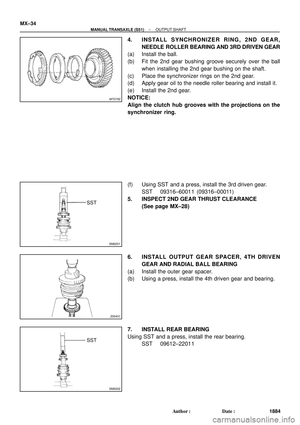
4. INSTALL SYNCHRONIZER RING, 2ND GEAR,
NEEDLE ROLLER BEARING AND 3RD DRIVEN GEAR
(a) Install the ball.
(b) Fit the 2nd gear bushing groove securely over the ball
when installing the 2nd gear bushing on the shaft.
(c) Place the synchronizer rings on the 2nd gear.
(d) Apply gear oil to the needle roller bearing and install it.
(e) Install the 2nd gear.
NOTICE:
Align the clutch hub grooves with the projections on the
synchronizer ring.
(f) Using SST and a press, install the 3rd driven gear.
SST 09316±60011 (09316±00011)
5. INSPECT 2ND GEAR THRUST CLEARANCE
(See page MX±28)
6. INSTALL OUTPUT GEAR SPACER, 4TH DRIVEN
GEAR AND RADIAL BALL BEARING
(a) Install the outer gear spacer.
(b) Using a press, install the 4th driven gear and bearing.
7. INSTALL REAR BEARING
Using SST and a press, install the rear bearing.
SST 09612±22011