Page 357 of 4770
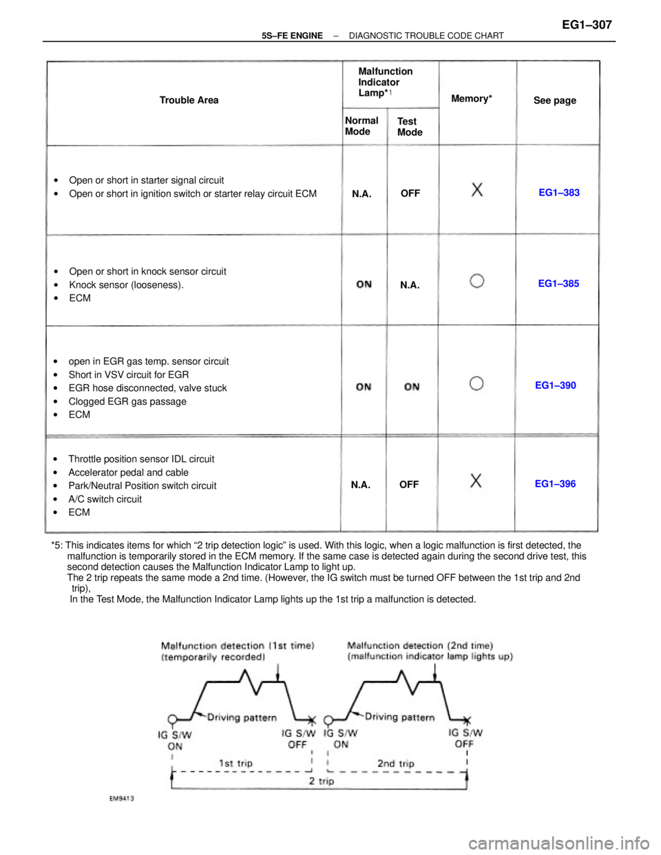
*5: This indicates items for which ª2 trip detection logicº is used. With this logic, when a logic malfunction is first detected, the
malfunction is temporarily stored in the ECM memory. If the same case is detected again during the second drive test, this
second detection causes the Malfunction Indicator Lamp to light up.
The 2 trip repeats the same mode a 2nd time. (However, the IG switch must be turned OFF between the 1st trip and 2nd
trip),
In the Test Mode, the Malfunction Indicator Lamp lights up the 1st trip a malfunction is detected.wopen in EGR gas temp. sensor circuit
wShort in VSV circuit for EGR
wEGR hose disconnected, valve stuck
wClogged EGR gas passage
wECM
wThrottle position sensor IDL circuit
wAccelerator pedal and cable
wPark/Neutral Position switch circuit
wA/C switch circuit
wECM wOpen or short in starter signal circuit
wOpen or short in ignition switch or starter relay circuit ECM
wOpen or short in knock sensor circuit
wKnock sensor (looseness).
wECMMalfunction
Indicator
Lamp*�
Normal
Mode Trouble AreaMemory*�
Test
ModeSee page
EG1±390EG1±385
EG1±396EG1±383
N.A.N.A.
N.A.
OFFOFF
± 5S±FE ENGINEDIAGNOSTIC TROUBLE CODE CHARTEG1±307
Page 368 of 4770
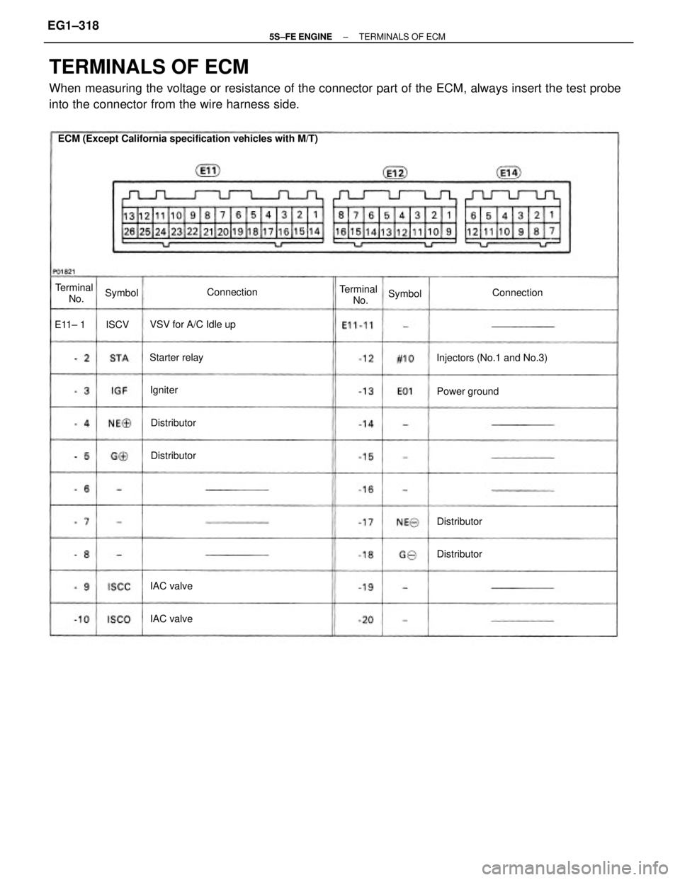
TERMINALS OF ECM
When measuring the voltage or resistance of the connector part of the ECM, always insert the test probe
into the connector from the wire harness side.
ECM (Except California specification vehicles with M/T)
Injectors (No.1 and No.3) VSV for A/C Idle upTerminal
No. Terminal
No.
Power ground Starter relayConnection
Connection
Distributor
Distributor
Distributor
Distributor
IAC valve
IAC valveSymbol Symbol
Igniter E11± 1 ISCV
± 5S±FE ENGINETERMINALS OF ECMEG1±318
Page 371 of 4770
*�: Only for California specification vehicles.
*�: Except California specification vehicles with A/T.wStoplight switch
w Stoplight
w Park/neutral position switch wDefogger relay
wTaillight relay
Park/neutral position switchPark/neutral position switch
Park/neutral position switch
Malfunction indicator lampData link connector 1 and 2 Data link connector 1 and 2No.1 vehicle speed sensor
Throttle position sensor
Throttle position sensorEGR gas temp. sensor
Circuit opening relay Data link connector 1Data link connector 2
Cruise control ECUO/D main switch Terminal
No.Terminal
No.Connection
A/C amplifier
EFI main relay Sensor ground
Sensor ground
A/C amplifierEFI main relay
Knock sensorStarter relay Connection Symbol
Symbol
Battery
± 5S±FE ENGINETERMINALS OF ECMEG1±321
Page 377 of 4770

MATRIX CHART OF PROBLEM SYMPTOMS
When the malfunction code is not confirmed in the diagnostic trouble code check and the problem still can
not be confirmed in the basic inspection, then proceed to this step and perform troubleshooting according
to the numbered order given in the table below.
*: Except California specification vehicles.
Park/Neutral position switch circuitManifold absolute pressure sensor circuit
VSV circuit for fuel pressure control
Ignition signal circuit (Spark test)
After acceleration pedal depressed
After acceleration pedal released
Switch condition signal circuit
Muffler explosion (after fire)No initial combustion
Back up power source circuit
Hesitation/Poor accelerationNo complete combustion
ECM power source circuit
Starter and Starter relay
Engine control module
High engine idle speed
Low engine idle speedUnder normal condition
During A/C operationEngine does not crank
A/C cut control circuit Starter signal circuit
Soon after starting
Fuel system circuit
When N to D shiftIncorrect first idle
Poor
Driveability
IAC valve circuit Difficult to
start
Injector circuit
Rough idling
Does not
start
Compression
Suspect area
Cold engine
Ignition coil Engine Stall
EG R system
Hot engine
Poor Idling
Spark plug
A/T faultylG±10,30*
IG±11,30 Distributor
Symptom
ST±19,21
See page
IG±8,28* IG±6,26*
Hunting
Surging
EG1±400
EG1±410 EG1±390
EG1±403
EG1±408
EG1±415
EG1±419EG1±383EG1±372
EG1±428EG1±396
EG1 ±424
AX1±68 EG1±23
IN±36
± 5S±FE ENGINEMATRIX CHART OF PROBLEM SYMPTOMSEG1±327
Page 433 of 4770

CIRCUIT DESCRIPTION
When the engine is cranked, the intake air flow is slow, so fuel vaporization is poor. A rich mixture
is therefore necessary in order to achieve good startability. While the engine is being cranked, the
battery positive voltage is applied to terminal STA of the ECM. The starter signal is mainly used to
increase the fuel injection volume for the starting injection control and after±start injection control.
DIAGNOSTIC CHART
HINT: This diagnostic chart is based on the premise that the engine is cranked normally. If the
engine is not cranked, proceed to the matrix chart of problem symptoms on page EG1±327, w
Open or short in starter signal circuit.
wOpen or short in ignition switch or starter
relay circuit.
wECM
Check for open in harness and connector
between ECM and relay.Proceed to next circuit inspection
shown on matrix chart (See page
E±G±327). Diagnostic Trouble Code Detecting Condition
Repair or replace harness or
connector.
WIRING DIAGRAM
No starter signal to ECM.
Check and replace ECM.Check for the test mode.Trouble Area
DTC 43 Starter Signal Circuit
DTC No.
± 5S±FE ENGINECIRCUIT INSPECTIONEG1±383
Page 434 of 4770
Setting the test mode.
(1) Turn ignition switch OFF.
(2) Connect terminals TE2 and E1 of DLC2.
(3) Turn ignition switch ON.
(Don't start the engine)
(4) Connect terminals TE1 and E1 of DLC2.
Check for open in harness and connector between engine control
module and starter relay (See page IN±31). Check output condition of diagnostic trouble code 43.
Proceed to next circuit inspection shown on
matrix chart (See page EG1±327).
Check and replace engine control module.Repair or replace harness or connector.
INSPECTION PROCEDURE
Check if code ª43º is output by the malfunc-
tion indicator lamp.
Code ª43º is output.
Start the engine.
Check if the code ª43º disappear.
Code ª43º is not output.
± 5S±FE ENGINECIRCUIT INSPECTIONEG1±384
Page 450 of 4770
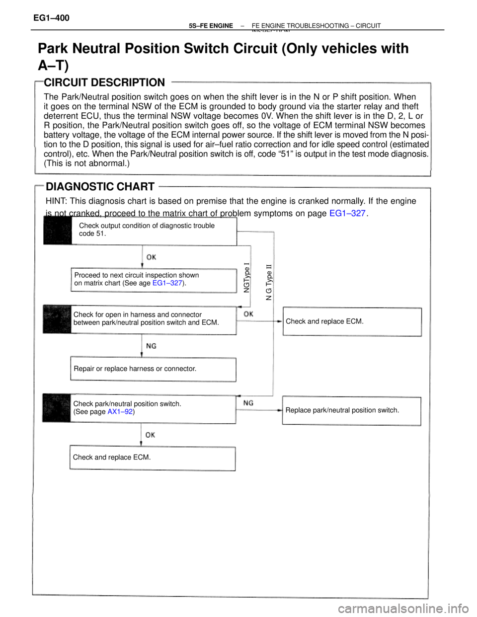
CIRCUIT DESCRIPTION
The Park/Neutral position switch goes on when the shift lever is in the N or P shift position. When
it goes on the terminal NSW of the ECM is grounded to body ground via the starter relay and theft
deterrent ECU, thus the terminal NSW voltage becomes 0V. When the shift lever is in the D, 2, L or
R position, the Park/Neutral position switch goes off, so the voltage of ECM terminal NSW becomes
battery voltage, the voltage of the ECM internal power source. If the shift lever is moved from the N posi-
tion to the D position, this signal is used for air±fuel ratio correction and for idle speed control (estimated
control), etc. When the Park/Neutral position switch is off, code ª51º is output in the test mode diagnosis.
(This is not abnormal.)
Park Neutral Position Switch Circuit (Only vehicles with
A±T)
Check for open in harness and connector
between park/neutral position switch and ECM.Check output condition of diagnostic trouble
code 51.
Proceed to next circuit inspection shown
on matrix chart (See age EG1±327).
Check park/neutral position switch.
(See page AX1±92) Repair or replace harness or connector.
Replace park/neutral position switch.Check and replace ECM.
Check and replace ECM.
N G Type II NGType I
DIAGNOSTIC CHART
HINT: This diagnosis chart is based on premise that the engine is cranked normally. If the engine
is not cranked, proceed to the matrix chart of problem symptoms on page EG1±327.
± 5S±FE ENGINEFE ENGINE TROUBLESHOOTING ± CIRCUITINSPECTION
EG1±400
Page 469 of 4770
CIRCUIT DESCRIPTION
Fuel pump control
The fuel pump is switched on (low voltage at terminal FC) when STA is on or while the NE signal
is input to the ECM.
In the diagram below, when the engine is cranked, current flows from terminal ST of the ignition
switch to the starter relay coil, the starter relay switches on and current flows to coil L1 of the circuit
opening relay. Thus the circuit opening relay switches on, power is supplied to the fuel pump and the
fuel pump operates.
When the STA signal and NE signal are input to the ECM, Tr is turned ON, current flows to coil L2
of the circuit opening relay, the relay switches on and the fuel pump operates.
While the NE signal is generated (engine running), the ECM keeps Tr ON (circuit opening relay ON)
and the fuel pump also keeps operating.
Fuel System Circuit
± 5S±FE ENGINECIRCUIT INSPECTIONEG1±419