Page 3335 of 4770
AB0119
I00144
I00178
ON
PI
(±) (+)
± DIAGNOSTICSCRUISE CONTROL SYSTEM
DI±915
1150 Author�: Date�:
INSPECTION PROCEDURE
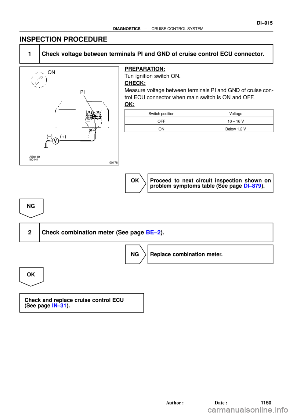
1 Check voltage between terminals PI and GND of cruise control ECU connector.
PREPARATION:
Tun ignition switch ON.
CHECK:
Measure voltage between terminals PI and GND of cruise con-
trol ECU connector when main switch is ON and OFF.
OK:
Switch positionVoltage
OFF10 ± 16 V
ONBelow 1.2 V
OK Proceed to next circuit inspection shown on
problem symptoms table (See page DI±879).
NG
2 Check combination meter (See page BE±2).
NG Replace combination meter.
OK
Check and replace cruise control ECU
(See page IN±31).
Page 3336 of 4770
I00291
Cruise Control ECU
4
PI
5
TC O
LG±R D DJ/C
J/C
B
B B O
LG±R 10
4DLC2
II3 11
C15
LG±R*1
11 DLC1
C15
J2
D4 D4
J3
D1LG±R
P±B
*2
*1: TMC Made, TMMK Made (5S±FE)
*2: TMMK Made (1MZ±FE) DI±916
± DIAGNOSTICSCRUISE CONTROL SYSTEM
1151 Author�: Date�:
Diagnosis Circuit
CIRCUIT DESCRIPTION
This circuit sends a signal to the ECU that outputs DTC.
WIRING DIAGRAM
DI091±11
Page 3337 of 4770
AB0119
I00169
I00179
ON
TC E1
± DIAGNOSTICSCRUISE CONTROL SYSTEM
DI±917
1152 Author�: Date�:
INSPECTION PROCEDURE
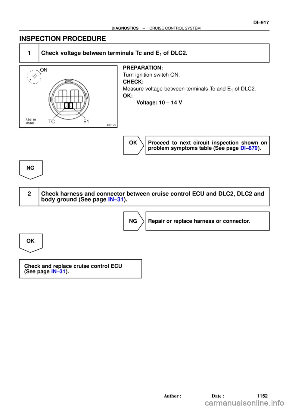
1 Check voltage between terminals Tc and E1 of DLC2.
PREPARATION:
Turn ignition switch ON.
CHECK:
Measure voltage between terminals Tc and E1 of DLC2.
OK:
Voltage: 10 ± 14 V
OK Proceed to next circuit inspection shown on
problem symptoms table (See page DI±879).
NG
2 Check harness and connector between cruise control ECU and DLC2, DLC2 and
body ground (See page IN±31).
NG Repair or replace harness or connector.
OK
Check and replace cruise control ECU
(See page IN±31).
Page 3347 of 4770

DI1KK±03
± DIAGNOSTICSENGINE IMMOBILISER SYSTEM
DI±927
1162 Author�: Date�:
PROBLEM SYMPTOMS TABLE
SymptomSuspect AreaSee page
Immobiliser is not set.
(Engine starts with key codes other than the registered key code.)2. ECMIN±31
Engine does not start.
1. Key
2. Wire harness
3. Transponder key coil
4. Amplifier
5. ECM*1
IN±31
BE±128
IN±31
Security indicator is always ON.
1. Security indicator
2. Wire harness
3. ECM*2
IN±31
IN±31
Security indicator is always ON.
(Although code has been registered in the automatic registration
mode, indicator is not OFF.)1. Wire harness
2. Transponder key coil
3. Amplifier
4. ECMIN±31
BE±128
IN±31
Security indicator is OFF
(When DTC of immobiliser is output)
1. Wire harness
2. Transponder key coil
3. Amplifier
4. ECMIN±31
BE±128
IN±31
Security indicator is OFF.
(When DTC of immobiliser is not output)1. Wire harness
2. ECMIN±31
IN±31
Security indicator is abnormally brinking.1. Wire harness
2. ECMIN±31
IN±31
*1 : Check that the key which did not start the engine has been registered and that it is possible to start with
other already registered key codes.
*2 : Finish the automatic registration mode because the mode might still remain.
Page 3430 of 4770
CYLINDER HEAD
1210 Author�: Date�:
(2) Secure the exhaust camshaft sub±gear to drive
gear w")
P03445
Drive Gear
Service
Bolt
Sub±Gear
P03356
P03241
3
26 54
1
P03357
EM±38
± ENGINE MECHANICAL (5S±FE)CYLINDER HEAD
1210 Author�: Date�:
(2) Secure the exhaust camshaft sub±gear to drive
gear with a service bolt.
Recommended service bolt:
Thread diameter6 mm
Thread pitch1.0 mm
Bolt length16 ± 20 mm (0.63 ± 0.79 in.)
HINT:
When removing the camshaft, make sure that the torsional
spring force of the sub±gear has been eliminated by the above
operation.
(3) Remove the 2 bolts and rear bearing cap.
(4) Uniformly loosen and remove the 6 bolts on the
No.1, No.2 and No.4 bearing caps in several
passes, in the sequence shown.
NOTICE:
Do not remove the No.3 bearing cap bolts at this stage.
(5) Remove the No.1, No.2 and No.4 bearing caps.
(6) Alternately loosen and remove the 2 bolts on the
No.3 bearing cap.
HINT:
�As the 2 No.3 bearing cap bolts are loosened, make sure
that the camshaft is lifted out straight and level.
�If the camshaft is not being lifted out straight and level, re-
tighten the 2 No.3 bearing cap bolts. Then reverse the or-
der of above steps from (6) to (1) and reset the knock pin
of the intake camshaft at 10 ± 45° BTDC, and repeat
steps from (2) to (6) once again.
NOTICE:
Do not pry on or attempt to force the camshaft with a tool
or other object.
(7) Remove the No.3 bearing cap and exhaust cam-
shaft.
Page 3543 of 4770
CYLINDER HEAD
EM±37
1323 Author�: Date�:
29. REMOVE OIL DIPSTICK AND GUIDE
(a) Re")
P12710
O±Ring
A01816
P12811Align Intake
P12871
Main Gear
Sub±Gear
Service Bolt Intake
± ENGINE MECHANICAL (1MZ±FE)CYLINDER HEAD
EM±37
1323 Author�: Date�:
29. REMOVE OIL DIPSTICK AND GUIDE
(a) Remove the bolt holding the dipstick guide to the LH cylin-
der head.
(b) Pull out the dipstick guide together with the dipstick from
the No.1 oil pan.
(c) Remove the O±ring from the dipstick guide.
30. REMOVE CYLINDER HEAD COVERS
Remove the 8 bolts, cylinder head cover and gasket. Remove
the 2 cylinder head covers.
31. REMOVE CAMSHAFTS OF RH CYLINDER HEAD
NOTICE:
Since the thrust clearance of the camshaft is small, the
camshaft must be held level while it is being removed. If the
camshaft is not kept level, the portion of the cylinder head
receiving the shaft thrust may crack or be damaged, caus-
ing the camshaft to seize or break. To avoid this, the follow-
ing steps should be carried out.
(a) Remove the intake camshaft.
(1) Align the timing marks (2 dot marks) of the camshaft
drive and driven gears by turning the camshaft with
a wrench.
(2) Secure the exhaust camshaft sub±gear to the main
gear with a service bolt.
Recommended service bolt:
Thread diameter6 mm
Thread pitch1.0 mm
Bolt length16 ± 20 mm (0.63 ± 0.79 in.)
Page 3545 of 4770
CYLINDER HEAD
EM±39
1325 Author�: Date�:
(2) Secur")
P12873Main Gear
Sub±GearService Bolt Intake
P12958
Intake
7
85
6
3
41
2
9
10
P12886
7
85 6
3 41 2
9 10 Exhaust
P12596
± ENGINE MECHANICAL (1MZ±FE)CYLINDER HEAD
EM±39
1325 Author�: Date�:
(2) Secure the exhaust camshaft sub±gear to the main
gear with a service bolt.
Recommended service bolt:
Thread diameter6 mm
Thread pitch1.0 mm
Bolt length16 ± 20 mm (0.63 ± 0.79 in.)
HINT:
When removing the camshaft, make sure that the torsional
spring force of the sub±gear has been eliminated by the above
operation.
(b) Uniformly loosen and remove the 10 bearing cap bolts, in
several passes, in the sequence shown.
(c) Remove the 5 bearing caps and intake camshaft.
(d) Remove the exhaust camshaft.
(1) Uniformly loosen and remove the 10 bearing cap
bolts, in several passes, in the sequence shown.
(2) Remove the 5 bearing caps, oil seal and exhaust
camshaft.
HINT:
�Arrange the camshafts in the correct order.
�Arrange the bearing caps in the correct order.
33. DISASSEMBLE EXHAUST CAMSHAFTS
(a) Mount the hexagonal wrench head portion of the cam-
shaft in a vise.
NOTICE:
Be careful not to damage the camshaft.
Page 3640 of 4770
BE0A4±04
I21685
E/G Room J/B No.2
� HEAD LH Fuse
(w/o Daytime Running Light)
� HEAD RH Fuse
(w/o Daytime Running Light)
� HEAD LH (UPR) Fuse
(w/ Daytime Running Light)
� HEAD RH (UPR) Fuse
(w/ Daytime Running Light)
� DOME Fuse
� ECU±B Fuse
� Headlight Control Relay
E/G Room R/B No.2
(w/ Daytime Running Light)
� HEAD LH (LWR) Fuse
� HEAD RH (LWR) Fuse
� DRL No.2 Fuse
� Daytime Running Light Relay No.2
� Daytime Running Light Relay No.3
� Daytime Running Light Relay No.4
Headlight
Instrument Panel J/B No.1
� GAUGE Fuse
� TAIL Fuse
� Taillight Control Relay
� Integration Relay
Daytime Running
Light Relay (Main)Ignition Switch
Combination Switch
� Light Control Switch
� Headlight Dimmer Switch
Door Courtesy Switch
Light Failure Sensor
Taillight
Automatic Light
Control Sensor
BE±22
± BODY ELECTRICALHEADLIGHT AND TAILLIGHT SYSTEM
2232 Author�: Date�:
2001 CAMRY (RM819U)
HEADLIGHT AND TAILLIGHT SYSTEM
LOCATION

*2: TMMK Made (1MZ±FE) DI±91")