Page 3317 of 4770
I00052
Throttle Position Sensor
3
4
± DIAGNOSTICSCRUISE CONTROL SYSTEM
DI±897
1132 Author�: Date�:
4 Check throttle position sensor.
PREPARATION:
Disconnect the throttle position sensor connector.
CHECK:
Measure resistance between terminals 3 and 4 of throttle posi-
tion sensor connector when the throttle valve is fully closed and
fully opened.
OK:
Throttle valve positionResistance
Fully opened1 MW or higher
Fully closedBelow 2.3 kW
NG Replace throttle position sensor.
OK
5 Check for open and short in harness and connector between cruise control ECU
and ECM (See page IN±31).
NG Repair or replace harness or connector.
OK
Check and replace cruise control ECU
(See page IN±31).
Page 3318 of 4770

I00285
Cruise Control ECU
2
STP±
8
L
J27
J/C
G±W A A
G±W 5
1R
1R
G±W 1
4 Stop Light Switch
2
3
W
7
1C4
1BG±B 4
B±R
FL BLOCK
F91 1
F4
B±G
FL MAIN
BatteryR±Y
Cruise Control
Actuator
3
4 J/C
A
J7 A
J7
W±B
1J
1JJ/C
AJ11
W±B
IG Instrument Panel J/B
STOP
ALT
C15
C15
Instrument Panel J/B
Instrument Panel J/BW±B
87 DI±898
± DIAGNOSTICSCRUISE CONTROL SYSTEM
1133 Author�: Date�:
Stop Light Switch Circuit
CIRCUIT DESCRIPTION
When the brake pedal is depressed, the stop light switch sends a signal to the ECU. When the ECU receives
this signal, it cancels the cruise control.
A fail±safe function is provided so that the cancel functions normally, even if there is a malfunction in the stop
light signal circuit.
The cancel conditions are: Battery positive voltage at terminal STP±
When the brake is ON, battery positive voltage normally is applied through the STOP fuse and stop light
switch to terminal STP± of the ECU, and the ECU turns the cruise control OFF.
If the harness connected to terminal STP± has an open circuit, terminal STP± will have battery positive volt-
age and the cruise control will be turned OFF.
Also, when the brake is ON, the magnetic clutch circuit is cut mechanically by the stop light switch, turning
the cruise control OFF. (See page DI±883 for operation of the magnetic clutch)
WIRING DIAGRAM
DI08T±11
Page 3320 of 4770
AB0119
I00142
I00173
ON
STP±
(±) (+)
DI±900
± DIAGNOSTICSCRUISE CONTROL SYSTEM
1135 Author�: Date�:
3 Check voltage between terminal STP± of cruise control ECU connector and
body ground.
PREPARATION:
(a) Remove the ECU with connectors still connected.
(b) Turn ignition switch ON.
CHECK:
Measure voltage between terminal STP± of cruise control ECU
connector and body ground, when the brake pedal is de-
pressed and released.
OK:
Depressed10 ± 14 V
ReleasedBelow 1 V
OK Proceed to next circuit inspection shown on
problem symptoms table (See page DI±879).
NG
4 Check for open in harness and connectors between terminal STP± of cruise con-
trol ECU and stop light switch (See page IN±31).
NG Repair or replace harness or connector.
OK
Check and replace cruise control ECU
(See page IN±31).
Page 3321 of 4770

*3: 5S±FE (w/o Immobiliser)
ECT No.2
SolenoidECT C15
6
C15 Y±B
L±B ECM
24 18 20
E8 E7 E7
*1 *2 *3 OD1
8216
E11
E9 E9
*1 *2 *")
I08432
S2OD 14Cruise Control ECU *1: 1MZ±FE
*2: 5S±FE (w/ Immobiliser)
*3: 5S±FE (w/o Immobiliser)
ECT No.2
SolenoidECT C15
6
C15 Y±B
L±B ECM
24 18 20
E8 E7 E7
*1 *2 *3 OD1
8216
E11
E9 E9
*1 *2 *3L±B L±B7
II2 J26
*1
J25*2
J/C
A
AA
± DIAGNOSTICSCRUISE CONTROL SYSTEM
DI±901
1136 Author�: Date�:
Electronically Controlled Transmission Communication Circuit
CIRCUIT DESCRIPTION
When driving uphill under the cruise control, in order to reduce shifting due to ON±OFF overdrive operation
and to provide smooth driving, when down shifting in the electronically controlled transmission occurs, a sig-
nal to prevent upshift until the end of the uphill slope is sent from the cruise control ECU to the electronically
controlled transmission.
Terminal ECT of the cruise control ECU detects the shift change signal (output to electronically controlled
transmission No. 2 solenoid) from the ECM.
If the vehicle speeds down, also when terminal ECT of the cruise control ECU receives down shifting signal,
it sends a signal from terminal OD to ECM to cut overdrive until the end of the uphill slope, and the gear shifts
are reduced and gear shift points in the electronically controlled transmission are changed.
WIRING DIAGRAM
DI08U±11
Page 3322 of 4770
AB0119
I00143
I00174
ON
O/D
(±) (+)
DI±902
± DIAGNOSTICSCRUISE CONTROL SYSTEM
1137 Author�: Date�:
INSPECTION PROCEDURE
1 Check operation of overdrive.
PREPARATION:
Test drive after engine warms up.
CHECK:
Check that overdrive ON e OFF occurs by operation of OD switch ON±OFF.
NG Check and repair electronically controlled
transmission (See page DI±389).
OK
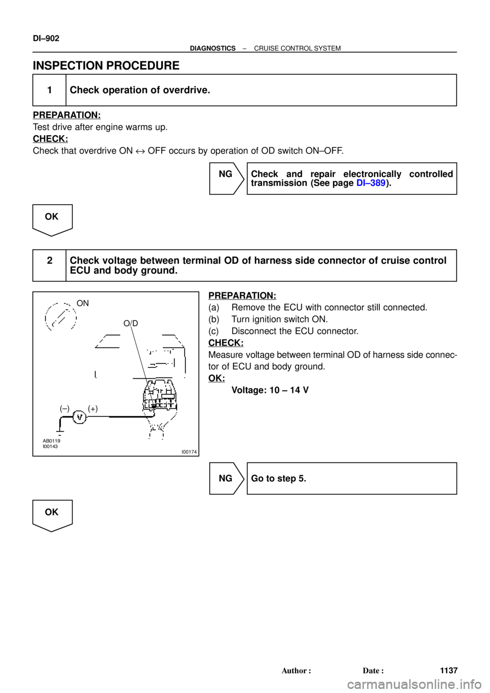
2 Check voltage between terminal OD of harness side connector of cruise control
ECU and body ground.
PREPARATION:
(a) Remove the ECU with connector still connected.
(b) Turn ignition switch ON.
(c) Disconnect the ECU connector.
CHECK:
Measure voltage between terminal OD of harness side connec-
tor of ECU and body ground.
OK:
Voltage: 10 ± 14 V
NG Go to step 5.
OK
Page 3323 of 4770
I00141
ECT
(±) (+)
± DIAGNOSTICSCRUISE CONTROL SYSTEM
DI±903
1138 Author�: Date�:
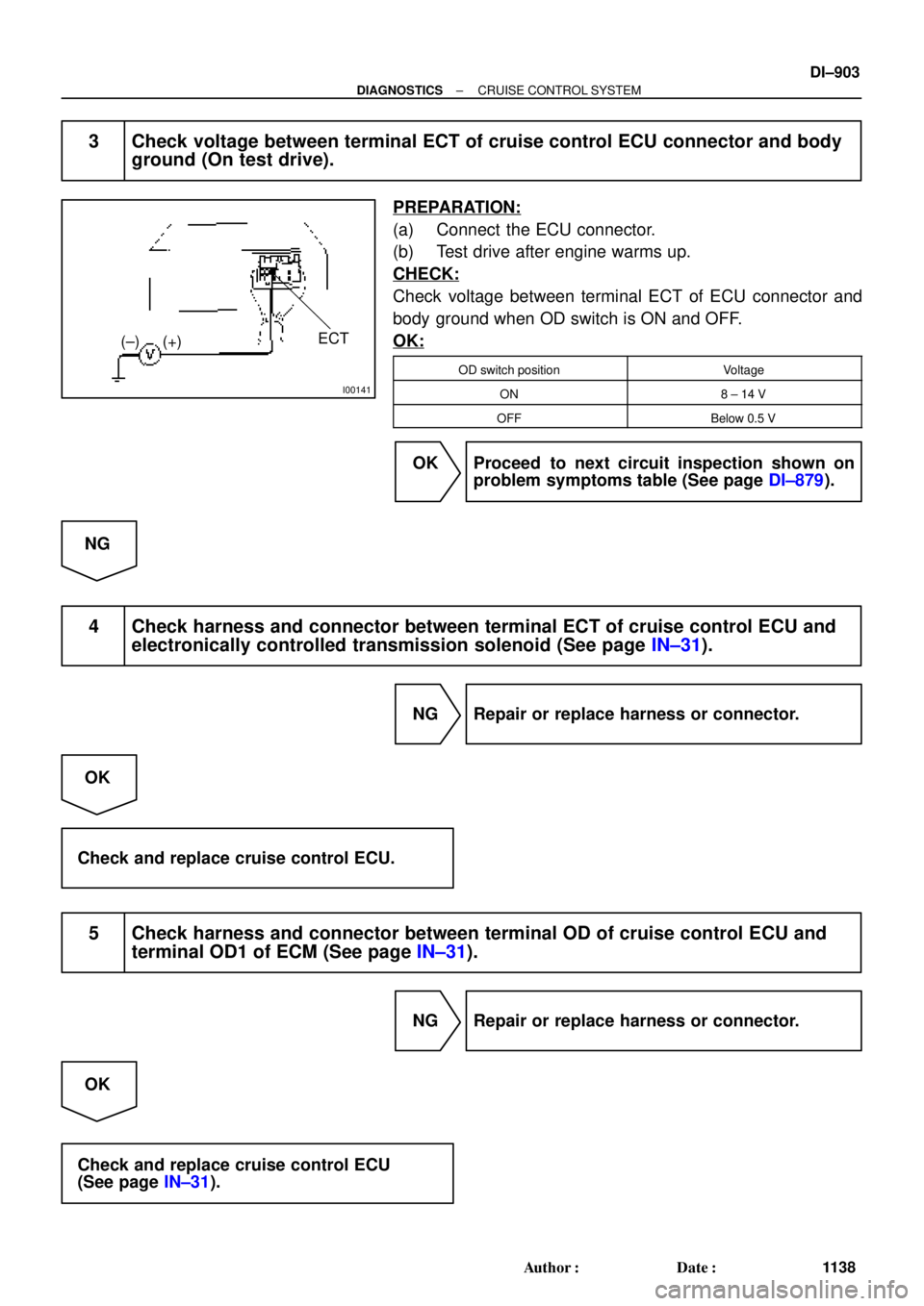
3 Check voltage between terminal ECT of cruise control ECU connector and body
ground (On test drive).
PREPARATION:
(a) Connect the ECU connector.
(b) Test drive after engine warms up.
CHECK:
Check voltage between terminal ECT of ECU connector and
body ground when OD switch is ON and OFF.
OK:
OD switch positionVoltage
ON8 ± 14 V
OFFBelow 0.5 V
OK Proceed to next circuit inspection shown on
problem symptoms table (See page DI±879).
NG
4 Check harness and connector between terminal ECT of cruise control ECU and
electronically controlled transmission solenoid (See page IN±31).
NG Repair or replace harness or connector.
OK
Check and replace cruise control ECU.
5 Check harness and connector between terminal OD of cruise control ECU and
terminal OD1 of ECM (See page IN±31).
NG Repair or replace harness or connector.
OK
Check and replace cruise control ECU
(See page IN±31).
Page 3324 of 4770
I08433
Cruise Control ECU
Instrument Panel J/B
Clutch Switch
PNP Switch GAUGE
1K
D 3 J29
J/C
J/C
J21 (5S±FE)
J24 (1MZ±FE) B±Y1JC15 For M/T
J/C
B±R A
A
A B±R
R±L R±L
2
1 D
J27 F
J28
F J28
R±L
R±L 2
II2
A
A
R±L210
B±R9
II2For A/T
FL BLOCK IG1
Battery Ignition Switch
2
4AM1
Instrument Panel J/B
AM1
1B1
1K2W
B±R
F91
F41
ALT
B±G
FL MAIN 11 DI±904
± DIAGNOSTICSCRUISE CONTROL SYSTEM
1139 Author�: Date�:
Park/Neutral Position Switch Circuit
CIRCUIT DESCRIPTION
When the shift position is except D, a signal is sent from the park/neutral position switch to the ECU. When
this signal is input during cruise control driving, the ECU cancels the cruise control.
WIRING DIAGRAM
DI08V±11
Page 3326 of 4770
AB0119
I00139
I00175
ON
D
(±) (+)
DI±906
± DIAGNOSTICSCRUISE CONTROL SYSTEM
1141 Author�: Date�:
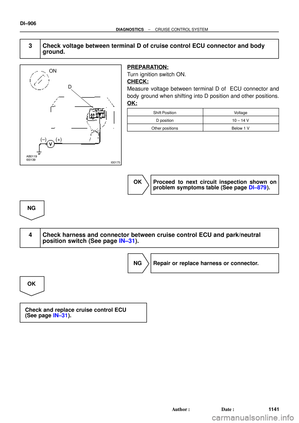
3 Check voltage between terminal D of cruise control ECU connector and body
ground.
PREPARATION:
Turn ignition switch ON.
CHECK:
Measure voltage between terminal D of ECU connector and
body ground when shifting into D position and other positions.
OK:
Shift PositionVoltage
D position10 ± 14 V
Other positionsBelow 1 V
OK Proceed to next circuit inspection shown on
problem symptoms table (See page DI±879).
NG
4 Check harness and connector between cruise control ECU and park/neutral
position switch (See page IN±31).
NG Repair or replace harness or connector.
OK
Check and replace cruise control ECU
(See page IN±31).


J24 (1MZ±FE) B±Y1JC15 For M/T
J/C
B±R A
A
A B±R
R±L R±L
2
1 D
J27 F
J28
F J28
R±L
R")