Page 3287 of 4770
I00298
1 (+)
2 (±)
± DIAGNOSTICSTHEFT DETERRENT SYSTEM
DI±867
1102 Author�: Date�:
INSPECTION PROCEDURE
1 Check engine hood courtesy switch.
PREPARATION:
(a) Remove engine hood lock assembly.
(b) Disconnect engine hood courtesy switch connector.
CHECK:
Check continuity between terminals 1 and 2 when engine hood
lock is locked and unlocked.
OK:
Engine hood lockTester connectionSpecified condition
LOCK±No continuity
UNLOCK1 ± 2Continuity
NG Replace engine hood courtesy switch.
OK
2 Check harness and connector between theft deterrent ECU and switch, switch
and body ground (See page IN±31).
NG Repair or replace harness or connector.
OK
Check and replace theft deterrent ECU
(See page IN±31).
Page 3290 of 4770

I00279CRUISE MAIN Indicator Light
DI1KS±03
BE4034
Indicator light
1.5 sec.0.5 sec.
ON
OFF
I00169
DLC2
Tc E 1
DI±870
± DIAGNOSTICSCRUISE CONTROL SYSTEM
1105 Author�: Date�:
PRE±CHECK
1. DIAGNOSIS SYSTEM
(a) Check the indicator.
(1) Turn the ignition switch ON.
(2) Check that the CRUISE MAIN indicator light comes
ON when the cruise control main switch is turned
ON, and that the indicator light goes OFF when the
main switch is turned OFF.
HINT:
If the indicator check result is not normal, proceed to trouble-
shooting (See page BE±2) for the combination meter section.
(b) Check the DTC.
HINT:
If a malfunction occurs in the No. 1 vehicle speed sensor or ac-
tuator, etc. during cruise control driving, the ECU actuates
AUTO CANCEL of the cruise control and turns on and off the
CRUISE MAIN indicator light to inform the driver of a malfunc-
tion. At the same time, the malfunction is stored in memory as
a DTC.
(c) Output of DTC using diagnosis check wire.
(1) Turn the ignition switch ON.
(2) Using SST, connect terminals Tc and E
1 of DLC2.
SST 09843±18020
(3) Read the DTC on the CRUISE MAIN indicator light.
Page 3291 of 4770
 (d) 5 times")
BE4032
BE4033I00021
Normal code
0.25 sec.
0.25 sec.
ON
OFF
ON
OFF
4 sec.1.5 sec. 0.5 sec.
2.5 sec.0.5 sec.1.5 sec.
Malfunction codes 11 and 21
Code 11 Code 21
H07517
I08438
DLC1
TC
E1(b) (d) 5 times
within 3 seconds
(c)
± DIAGNOSTICSCRUISE CONTROL SYSTEM
DI±871
1106 Author�: Date�:
HINT:
If the DTC is not output, inspect the diagnosis circuit (See page
DI±916).
As an example, the blinking patterns for codes; normal, 11 and
21 are shown in the illustration.
2. USING TOYOTA HAND±HELD TESTER
(a) Hook up the TOYOTA hand±held tester to the DLC2.
(b) Monitor the ECU data by following the prompts on the tes-
ter screen.
HINT:
TOYOTA hand±held tester has a ºSnapshotº function which re-
cords the monitored data.
Please refer to the TOYOTA hand±held tester operator's manu-
al for further details.
3. DTC CLEARANCE (ERASE MODE)
HINT:
During in the erase mode, diag detection does not work.
(a) Stop the vehicle.
(b) Using SST, connect terminals Tc and E
1 of DLC1.
SST 09843±18020
(c) Pull the cruise control switch to CANCEL.
(d) On the above metioned condition, turn on the cruise con-
trol main switch 5 times within 3 seconds.
Page 3294 of 4770

(2)
(1)
No.Operation MethodCRUISE MAIN Indicator Light
Blinking PatternDiagnosis
1 Turn SET/COAST switch ON
2Turn RES/ACC switch ON
3Turn CANCEL switch ON
Turn stop light switch ON
Depress")
N17520
(1)
(2)
(1)
No.Operation MethodCRUISE MAIN Indicator Light
Blinking PatternDiagnosis
1 Turn SET/COAST switch ON
2Turn RES/ACC switch ON
3Turn CANCEL switch ON
Turn stop light switch ON
Depress brake pedal
Turn PNP switch OFF
(Shift to except D position)
4Drive at about 40 km/h
(25 mph)or higher
Drive at about 40 km/h
(25 mph) or below
LightON
OFF
LightON
OFF
LightON
OFFSwitch ON
Switch OFF
LightON
OFFSwitch OFF
Switch ONSET/COAST switch circuit
is normal
RES/ACC switch circuit
is normal
CANCEL switch circuit
is normal
Stop light switch circuit
is normal
PNP switch circuit is
normal
Vehicle Speed Sensor is
normal
LightON
OFF LightON
OFF
1sec.
0.25 sec.0.25 sec.
Turn clutch switch OFF
(Depress clutch pedal)Clutch switch circuit
is normal
DI±874
± DIAGNOSTICSCRUISE CONTROL SYSTEM
1109 Author�: Date�:
5. INPUT SIGNAL CHECK
HINT:
(1) For check No.1 ~ No.3
�Turn ignition switch ON.
(2) For check No.4
�Jack up the vehicle.
�Start the engine.
�Shift to D position.
(a) Pull the control switch to SET/COAST or RES/ACC posi-
tion and hold it down or up (1).
(b) Push the main switch ON (2).
(c) Check that the CRUISE MAIN indicator light blinks twice
or 3 times repeatedly after 3 seconds.
(d) Turn the SET/COAST or RES/ACC switch OFF.
(e) Operate each switch as listed in the table below.
(f) Read the blinking pattern of the CRUISE MAIN indicator
light.
(g) After performing the check, turn the main switch OFF.
HINT:
When 2 or more signals are input to the ECU, the lowest num-
bered code will be displayed first.
Page 3295 of 4770

DI08I±08
± DIAGNOSTICSCRUISE CONTROL SYSTEM
DI±875
111 0 Author�: Date�:
DIAGNOSTIC TROUBLE CODE CHART
If a malfunction code is displayed during the DTC check, check the circuit listed for that code in the table
below and proceed to the appropriate page.
DTC No.
(See Page)Circuit InspectionTrouble Area
11, 15
(DI±881)Actuator Motor Circuit
�Actuator motor
�Harness or connector between cruise control ECU and
actuator motor
�Cruise control ECU
12
(DI±883)Actuator Magnetic Clutch Circuit
�STOP Fuse
�Stop light switch
�Actuator magnetic clutch
�Harness or connector between cruise control ECU and
actuator magnetic clutch, actuator magnetic clutch and body
ground
�Cruise control ECU
14
(DI±886)Actuator Mechanical Malfunction�Actuator motor (actuator lock: motor, arm)
�Cruise control ECU
21
(DI±888)Open in Vehicle Speed Sensor Circuit
�Combination meter
�Harness or connector between cruise control ECU and com-
bination meter, combination meter and vehicle speed sensor
�Vehicle speed sensor
�Cruise control ECU
23
(DI±891)Vehicle Speed Signal Abnormal�Vehicle speed sensor
�Cruise control ECU
32
(DI±892)Control Switch Circuit
�Cruise control switch
�Harness or connector between cruise control ECU and cruise
control switch, cruise control switch and body ground
�Cruise control ECU
41Cruise control ECU�Cruise control ECU
42Source voltage drop�Power source
51
(DI±895)Idle Signal Circuit
�Throttle position sensor
�Harness or connector between ECM and throttle position
sensor
�Harness or connector between cruise control ECU and ECM
�Cruise control ECU
Page 3296 of 4770
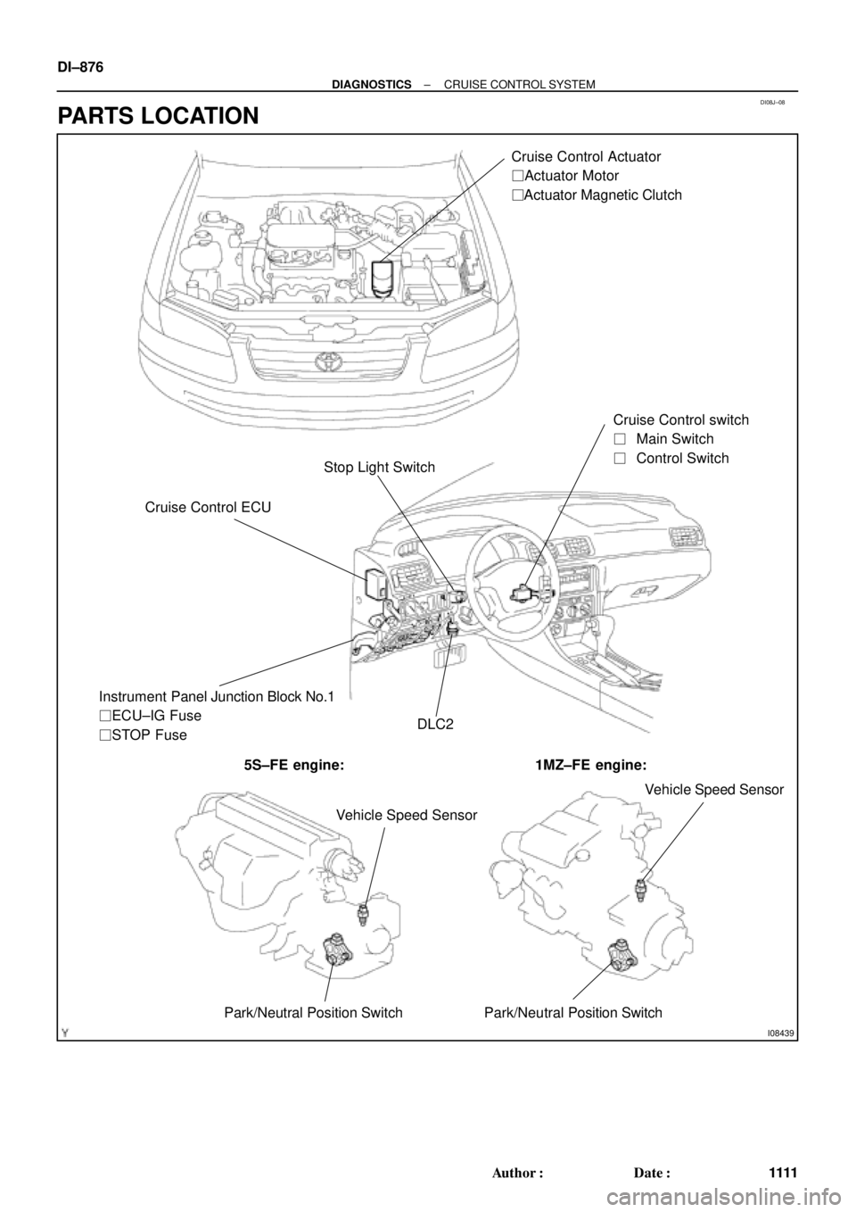
DI08J±08
I08439
Stop Light SwitchCruise Control Actuator
� Actuator Motor
� Actuator Magnetic Clutch
Cruise Control ECUCruise Control switch
��Main Switch
��Control Switch
DLC2 Instrument Panel Junction Block No.1
� ECU±IG Fuse
� STOP Fuse
5S±FE engine: 1MZ±FE engine:
Vehicle Speed Sensor
Park/Neutral Position Switch Park/Neutral Position SwitchVehicle Speed Sensor
DI±876
± DIAGNOSTICSCRUISE CONTROL SYSTEM
1111 Author�: Date�:
PARTS LOCATION
Page 3297 of 4770
Wiring ColorConditionSTD Voltage (V)
STP± e GND GWWBDepress brake pedal1")
DI1KT±06
I00293
C15
± DIAGNOSTICSCRUISE CONTROL SYSTEM
DI±877
111 2 Author�: Date�:
TERMINALS OF ECU
Symbols (Terminals No.)Wiring ColorConditionSTD Voltage (V)
STP± e GND GWWBDepress brake pedal10 ± 16 VSTP e GND
(C15±2 e C15±16)G±W e W±BRelease brake pedalBelow 1 V
DGND (C15 3C15 16)BRWBShift to positions except DBelow 1 VD e GND (C15±3 e C15±16)B±R e W±BShift to D position10 ± 16 V
PIGND (C15 4C15 16)OWB
Ignition switch ON
Cruise control main switch ONBelow 1.2 V
PI e GND (C15±4 e C15±16)O e W±BIgnition switch ON
Cruise control main switch OFF10 ± 16 V
TCGNDIgnition switch ON10 ± 16 VTC e GND
(C15±5 e C15±16)LG±R e W±BIgnition switch ON
Connect terminals Tc and E1 of diagnostic check connectorBelow 1 V
ECT e GND LBWB
During driving
Gear position 3rd10 ± 16 VECT e GND
(C15±6 e C15±16)L±B e W±BDuring driving
Gear position O/DBelow 1 V
MC e GND RBWB
During cruise control driving
COAST switch held ON9 ± 15 VMC e GND
(C15±7 e C15±16)R±B e W±BDuring cruise control driving
ACC switch held ONBelow 1 V
L e GND GBWBDuring cruise control driving9 ± 15 VL e GND
(C15±8 e C15±16)G±B e W±BExcept during cruise control drivingBelow 1 V
B e GND
(C15±9 e C15±16)B±R e W±BIgnition switch ON10 ± 16 V
Ignition switch ON10 ± 16 V
CCSGND
Ignition switch ON
CANCEL switch held ON4.2 ± 8.8 V
CCS e GND
(C15±10 e C15±16)W e W±BIgnition switch ON
SET/COAST switch held ON2.5 ± 6.3 V
Ignition switch ON
RES/ACC switch held ON0.8 ± 3.7 V
Page 3299 of 4770

DI08L±13
± DIAGNOSTICSCRUISE CONTROL SYSTEM
DI±879
111 4 Author�: Date�:
PROBLEM SYMPTOMS TABLE
SymptomSuspect AreaSuspect AreaSee pageSee
page
SET not occourring or CANCEL occurring.
(DTC is Normal)
3. Main Switch Circuit
(Cruise control switch)
4. Vehicle Speed Sensor
5. Control Switch Circuit
(Cruise control switch)
6. Stop Light Switch Circuit
7. Park/Neutral Position Switch Circuit
8. Clutch Switch
9. Actuator Motor Circuit
10.Cruise Control Cable
11. Cruise Control ECU
DI±912
DI±888
DI±892
DI±898
DI±904
DI±907
DI±881
DI±918
IN±31
SET not occurring or CANCEL occurring.
(DTC dose not output)1. ECU Power Source Circuit
2. Cruise Control ECUDI±909
IN±31
Actual vehicle speed deviates above or below the set speed.
1. Cruise Control Cable
2. Vehicle Speed Signal Abnormal
3. Electronically Controlled Transmission
Communication Circuit
4. Actuator Motor Circuit
5. Idle Signal Circuit
(Main throttle position sensor)
6. Cruise Control ECUDI±918
DI±891
DI±901
DI±881
DI±895
IN±31
Gear shifting frequent between 3rd O/D when driving on uphill
road. (Hurting)1. Electronically Controlled Transmission
Communication Circuit
2. Cruise Control ECU
DI±901
IN±31
Cruise control not cancelled, even when brake pedal is de-
pressed.
1. Cruise Control Cable
2. Stop Light Switch Circuit
3. Actuator Motor Circuit
4. Cruise Control ECUDI±918
DI±898
DI±881
IN±31
Cruise control not cancelled, even when transmission is shifted to
ºNº postion.
1. Cruise Control Cable
2. Park/Neutral Position Switch Circuit
3. Actuator Motor Circuit
4. Cruise Control ECUDI±918
DI±904
DI±881
IN±31
Cruise control not cancelled, even when clutch pedal is de-
pressed.
1. Cruise Control Cable
2. Clutch Switch Circuit
3. Actuator Motor Circuit
4. Cruise Control ECUDI±918
DI±907
DI±881
IN±31
Control switch does not operate.
(SET/COAST, ACC/RES, CANCEL not possible)
1. Cruise Control Cable
2. Control Switch Circuit
3. Actuator Motor Circuit
4. Cruise Control ECUDI±918
DI±892
DI±881
IN±31
SET possible at 40 km/h (25 mph) or less, or CANCEL does not
operate at 40 km/h (25 mph) or less.
1. Cruise Control Cable
2. Vehicle Speed Signal Abnormal
3. Actuator Motor Circuit
4. Cruise Control ECUDI±918
DI±891
DI±881
IN±31
Poor response is in ACCEL and RESUME modes.
1. Cruise Control Cable
2. Electronically Controlled Transmission
Communication Circuit
3. Actuator Motor Circuit
4. Cruise Control ECUDI±918
DI±901
DI±881
IN±31
O/D does not resume, even though the road is not uphill.
1. Electronically Controlled Transmission
Communication Circuit
2. Cruise Control ECU
DI±901
IN±31