Page 3253 of 4770
DI06P±05
I00233
I00234
I00236
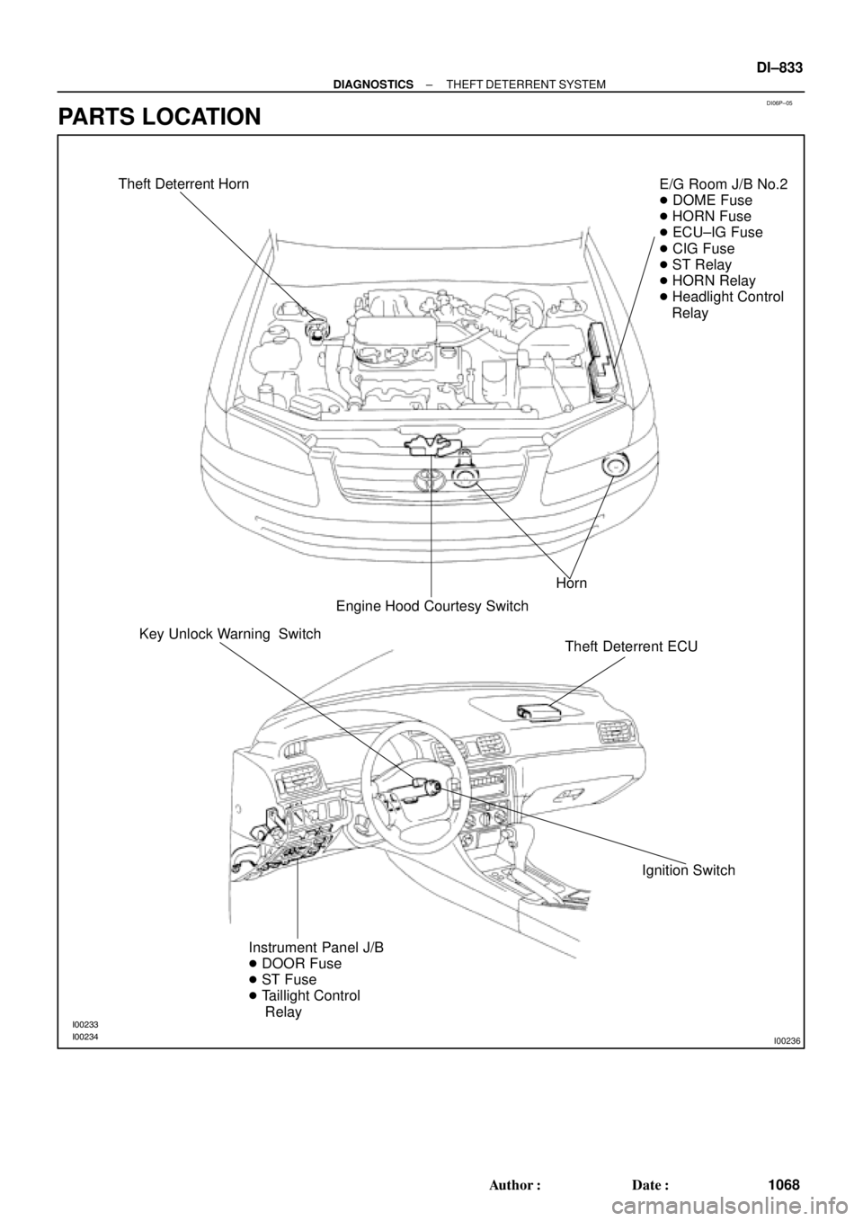
Theft Deterrent Horn
Horn
Engine Hood Courtesy SwitchE/G Room J/B No.2
� DOME Fuse
� HORN Fuse
� ECU±IG Fuse
� CIG Fuse
� ST Relay
� HORN Relay
� Headlight Control
Relay
Theft Deterrent ECU
Ignition Switch Key Unlock Warning Switch
Instrument Panel J/B
� DOOR Fuse
� ST Fuse
� Taillight Control
Relay
± DIAGNOSTICSTHEFT DETERRENT SYSTEM
DI±833
1068 Author�: Date�:
PARTS LOCATION
Page 3255 of 4770
Wiring ColorConditionSTD Value
CTY e ERWWB
Door courtesy switch ºONº")
DI1KV±03
I01920
T4
T3
± DIAGNOSTICSTHEFT DETERRENT SYSTEM
DI±835
1070 Author�: Date�:
TERMINALS OF ECU
Symbols (Terminals No.)Wiring ColorConditionSTD Value
CTY e ERWWB
Door courtesy switch ºONº
(Rear door opened)Below 1 WCTY e E
(T4±1 e T3±7)R±W e W±BDoor courtesy switch ºOFFº
(Rear door closed)1 MW or higher
DSWL e ERYWB
Luggage compartment door courtesy switch ºONº
(Luggage compartment door opened)Below 1 WDSWL e E
(T4±2 e T3±7)R±Y e W±BLuggage compartment door courtesy switch ºOFFº
(Luggage compartment door closed)1 MW or higher
DSWH e EBWB
Engine hood courtesy switch ºONº
(Engine hood opened)Below 1 WDSWH e E
(T4±3 e T3±7)B e W±BEngine hood courtesy switch ºOFFº
(Engine hood closed)1 MW or higher
DSWD e ERGWB
Door courtesy switch ºONº
(Driver's door opened)Below 1 WDSWD e E
(T4±4 e T3±7)R±G e W±BDoor courtesy switch ºOFFº
(Driver's door Closed)1 MW or higher
DSWP e ERGWB
Door courtesy switch ºONº
(Passenger's door opened)Below 1 WDSWP e E
(T4±5 e T3±7)R±G e W±BDoor courtesy switch ºOFFº
(Passenger's door closed)1 MW or higher
KSW e ELBWB
Key unlock warning switch ºONº
(Key inserted)Below 1 WKSW e E
(T4±6 e T3±7)L±B e W±BKey unlock warning switch ºOFFº
(Key removed)1 MW or higher
LUG e E GWWBLuggage compartment door key lock and unlock switch ºONºBelow 1 WLUG e E
(T4±7 e T3±7)G±W eW±BLuggage compartment door key lock and unlock switch ºOFFº1 MW or higher
L2 e E LWWB
Door key lock and unlock switch ºLOCKº
(Driver's and passenger's doors)Below 1 WL2 e E
(T4±8 e T3±7)L±W e W±BDoor key lock and unlock switch ºUNLOCKº
(Driver's and passenger's doors)1 MW or higher
UL3 e E RGWB
Door key lock and unlock switch ºUNLOCKº
(Driver's door)Below 1 WUL3 e E
(T4±9 e T3±7)R±G e W±BDoor key lock and unlock switch ºLOCKº
(Driver's door)1 MW or higher
UL2 e E LWB
Door key lock and unlock switch ºUNLOCKº
(passenger's door)Below 1 WUL2 e E
(T4±10 e T3±7)L e W±BDoor key lock and unlock switch ºLOCKº
(passenger's door)1 MW or higher
Page 3257 of 4770

DI06R±06
Details of Problem
The theft deterrent system cannot be set
Inspecting Circuit*1See page
DI±838 1. Indicator light circuit
2. ECU power source circuit
3. Key unlock warning switch circuit
7. Door courtesy switch circuit
8. Door unlock detection switch circuit
9. Engine hood courtesy switch circuit
The indicator light does not blink when system is setIndicator light circuit
When the
system is
set
When the rear doors are unlocked
When the luggage compartment door is opened
by a method other than the key4. Luggage compartment door key
lock and unlock switch circuit
5. Luggage compartment door
courtesy switch circuit
When the engine hood is opened
The system
does not
operateDoor unlock detection switch circuit
Luggage compartment door
courtesy switch circuit
Engine hood courtesy switch circuit
While the system is
in warning operation
Horns do not sound
Theft deterrent horn does not sound
Headlights do not flash
Taillights do not flash
The door lock is not locked in unlock conditionHorn relay circuit
Theft deterrent horn circuit
Headlight control relay circuit
Taillight control relay circuit
Door unlock detection switch circuit
6. Door key lock and unlock switch
circuit
It is not canceled when the ignition key is turned to
ACC or ON position
It still operates when the luggage compartment door is
opened with the key When the
system is
set
Ignition switch circuit
Luggage compartment door key
lock and unlock switch circuit
System is still set even when a rear door is open
Door courtesy switch circuit
Even when the
system is not
setHorns sound
Theft deterrent horn sounds
Headlights stay on
Taillights stay onHorn relay circuit
Theft deterrent horn circuit
Headlight control relay circuit
Taillight control relay circuit
DI±840
DI±853
DI±855
DI±858
DI±855
DI±864
DI±862
DI±866
DI±838
DI±862
DI±858
DI±866
DI±845
DI±843
DI±847
DI±849
DI±862
DI±851
DI±855
DI±864
DI±845
DI±843
DI±847
DI±849
*1: If numbers are given to the circuit proceed with troubleshooting in the order indicated by those numbers.
± DIAGNOSTICSTHEFT DETERRENT SYSTEM
DI±837
1072 Author�: Date�:
PROBLEM SYMPTOMS TABLE
Proceed to the reference page shown in the matrix chart below for each malfunction symptom and trouble-
shoot for each circuit.
HINT:
Troubleshooting of the theft deterrent system is based on the premise that the door lock control system is
operating normally. Accordingly, before troubleshooting the theft deterrent system, first make certain that
the door lock control system is operating normally.
Page 3258 of 4770
DI06S±04
I04447
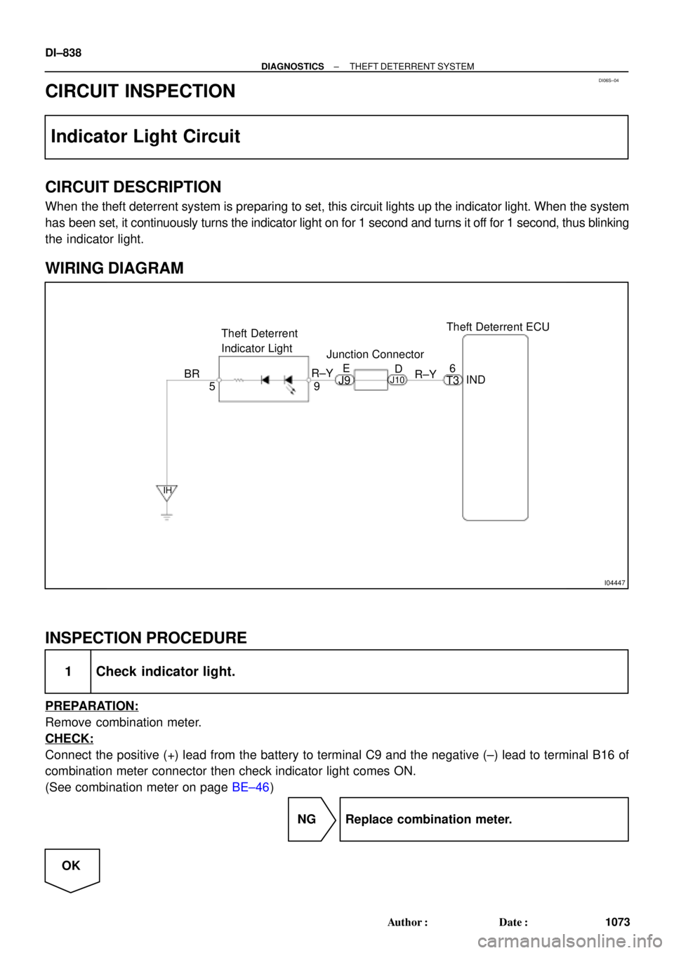
Theft Deterrent ECU
9 Theft Deterrent
Indicator Light
5IND 6
BR
IH
R±Y
T3 R±YE
D
J9J10
Junction Connector
DI±838
± DIAGNOSTICSTHEFT DETERRENT SYSTEM
1073 Author�: Date�:
CIRCUIT INSPECTION
Indicator Light Circuit
CIRCUIT DESCRIPTION
When the theft deterrent system is preparing to set, this circuit lights up the indicator light. When the system
has been set, it continuously turns the indicator light on for 1 second and turns it off for 1 second, thus blinking
the indicator light.
WIRING DIAGRAM
INSPECTION PROCEDURE
1 Check indicator light.
PREPARATION:
Remove combination meter.
CHECK:
Connect the positive (+) lead from the battery to terminal C9 and the negative (±) lead to terminal B16 of
combination meter connector then check indicator light comes ON.
(See combination meter on page BE±46)
NG Replace combination meter.
OK
Page 3259 of 4770
± DIAGNOSTICSTHEFT DETERRENT SYSTEM
DI±839
1074 Author�: Date�:
2 Check harness and connector between theft deterrent ECU and indicator light,
indicator light and body ground (See page IN±31).
NG Repair or replace harness or connector.
OK
Check and replace theft deterrent ECU.*1
*1: When there is a malfunction that the theft deterrent system
cannot be set, proceed to the next numbered circuit inspection
shown on problem symptoms table (See page DI±837).
Page 3260 of 4770
I00238
Theft Deterrent ECU
+B2
E
W±B L±WL±W
J/C
T4
T3
J/C
1G 1
A
AD
8
1W DOME12
R
IF
R
E
T3
+B1
DOOR
J34
C
1B 1D
B±R SHORT PIN
E/G Room J/B No.2
1 4
FL BLOCK
C
R B
F6
F4F9
FL MAIN
Battery
B±G2A1
2J
111
1
7 ALT 1
1
J17 J16
Instrument Panel J/B
Instrument Panel J/B
J5
J/C
R±Y12 DIODE (DOME)
W±B
DI±840
± DIAGNOSTICSTHEFT DETERRENT SYSTEM
1075 Author�: Date�:
ECU Power Source Circuit
CIRCUIT DESCRIPTION
This circuit provides power to operate the theft deterrent ECU.
WIRING DIAGRAM
DI06T±06
Page 3261 of 4770
I00268
I00269
I00275
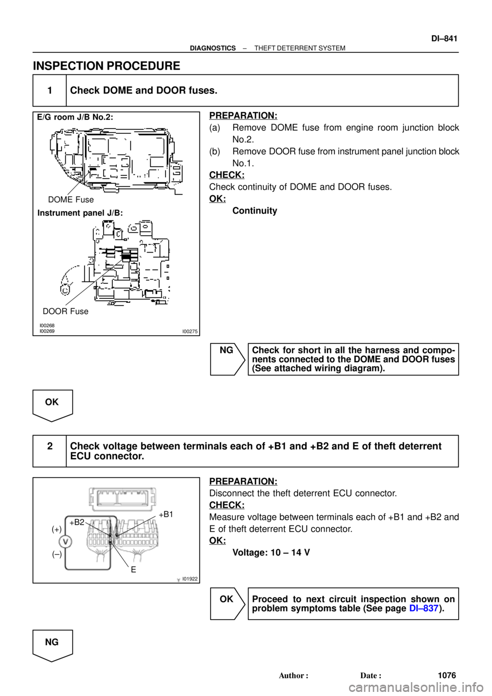
E/G room J/B No.2:
Instrument panel J/B:DOME Fuse
DOOR Fuse
I01922E+B1
+B2
(+)
(±)
± DIAGNOSTICSTHEFT DETERRENT SYSTEM
DI±841
1076 Author�: Date�:
INSPECTION PROCEDURE
1 Check DOME and DOOR fuses.
PREPARATION:
(a) Remove DOME fuse from engine room junction block
No.2.
(b) Remove DOOR fuse from instrument panel junction block
No.1.
CHECK:
Check continuity of DOME and DOOR fuses.
OK:
Continuity
NG Check for short in all the harness and compo-
nents connected to the DOME and DOOR fuses
(See attached wiring diagram).
OK
2 Check voltage between terminals each of +B1 and +B2 and E of theft deterrent
ECU connector.
PREPARATION:
Disconnect the theft deterrent ECU connector.
CHECK:
Measure voltage between terminals each of +B1 and +B2 and
E of theft deterrent ECU connector.
OK:
Voltage: 10 ± 14 V
OK Proceed to next circuit inspection shown on
problem symptoms table (See page DI±837).
NG
Page 3262 of 4770
DI±842
± DIAGNOSTICSTHEFT DETERRENT SYSTEM
1077 Author�: Date�:
3 Check for open in harness and connector between ECU and body ground
(See page IN±31).
NG Repair or replace harness or connector.
OK
Check and repair harness and connector be-
tween ECU and battery.