Page 3240 of 4770
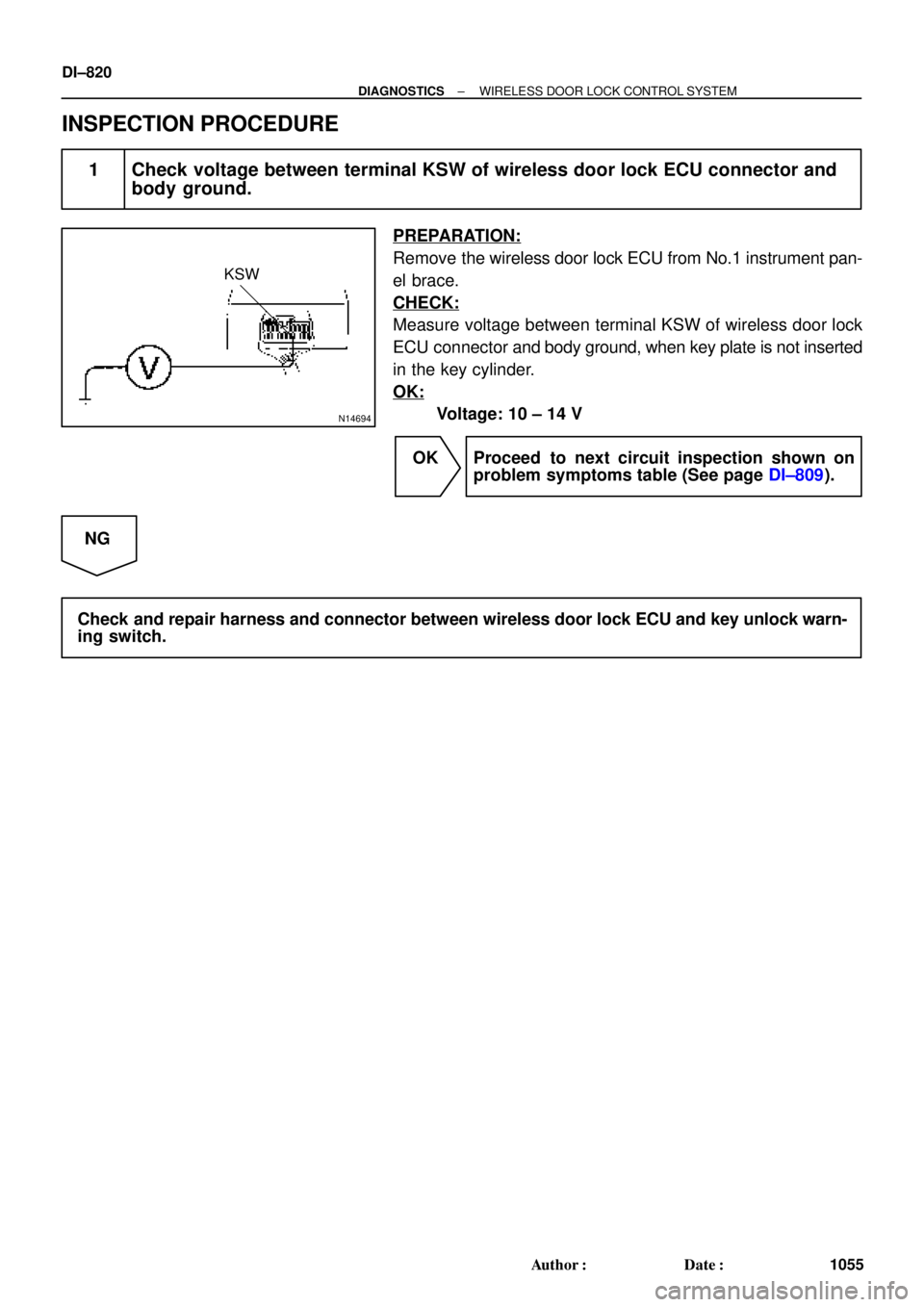
N14694
KSW
DI±820
± DIAGNOSTICSWIRELESS DOOR LOCK CONTROL SYSTEM
1055 Author�: Date�:
INSPECTION PROCEDURE
1 Check voltage between terminal KSW of wireless door lock ECU connector and
body ground.
PREPARATION:
Remove the wireless door lock ECU from No.1 instrument pan-
el brace.
CHECK:
Measure voltage between terminal KSW of wireless door lock
ECU connector and body ground, when key plate is not inserted
in the key cylinder.
OK:
Voltage: 10 ± 14 V
OK Proceed to next circuit inspection shown on
problem symptoms table (See page DI±809).
NG
Check and repair harness and connector between wireless door lock ECU and key unlock warn-
ing switch.
Page 3241 of 4770
I00223
Wireless Door
Lock ECU Theft Deterrent
ECU
Integration Relay
Door Cour-
tesy Switch R±W
R±G DSWD
CTY
DSWPR±WIN2 1G
1S J10 J9
J33 J34
ED A 4
4
6
Rear RH
Rear LHFront RH
Front LH8 1S1G R±G R±G
R±GR±W
R±G R±W R±W
4
CTY
5
6 1C
14
1
2 712
11 11 R±W J33J33
J34D
DE
R±G
J33
J33
J34 DE
ER±W
T4W6 T4
T4
IN2R±G Instrument Panel J/B
1
± DIAGNOSTICSWIRELESS DOOR LOCK CONTROL SYSTEM
DI±821
1056 Author�: Date�:
Door Courtesy Switch Circuit
CIRCUIT DESCRIPTION
The door courtesy switch comes ON when the door is opened and goes OFF when door is closed. Further-
more. the door courtesy switch circuit has terminal +B connected inside the theft deterrent ECU . Battery
positive voltage is applied to terminal DSWD of the theft deterrent ECU when all doors are closed, i.e., when
the door courtesy switches of all doors are OFF.
WIRING DIAGRAM
DI05W±03
Page 3242 of 4770
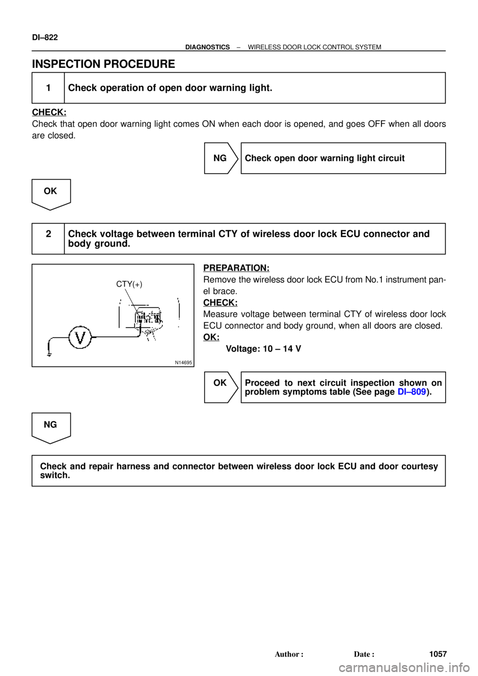
N14695
CTY(+)
DI±822
± DIAGNOSTICSWIRELESS DOOR LOCK CONTROL SYSTEM
1057 Author�: Date�:
INSPECTION PROCEDURE
1 Check operation of open door warning light.
CHECK:
Check that open door warning light comes ON when each door is opened, and goes OFF when all doors
are closed.
NG Check open door warning light circuit
OK
2 Check voltage between terminal CTY of wireless door lock ECU connector and
body ground.
PREPARATION:
Remove the wireless door lock ECU from No.1 instrument pan-
el brace.
CHECK:
Measure voltage between terminal CTY of wireless door lock
ECU connector and body ground, when all doors are closed.
OK:
Voltage: 10 ± 14 V
OK Proceed to next circuit inspection shown on
problem symptoms table (See page DI±809).
NG
Check and repair harness and connector between wireless door lock ECU and door courtesy
switch.
Page 3243 of 4770
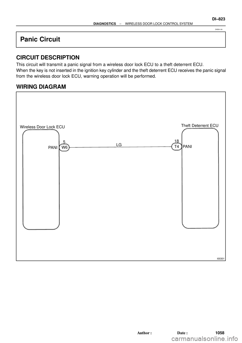
I00301
Wireless Door Lock ECUTheft Deterrent ECU
518
LG
PANI
PANIW6T4
± DIAGNOSTICSWIRELESS DOOR LOCK CONTROL SYSTEM
DI±823
1058 Author�: Date�:
Panic Circuit
CIRCUIT DESCRIPTION
This circuit will transmit a panic signal from a wireless door lock ECU to a theft deterrent ECU.
When the key is not inserted in the ignition key cylinder and the theft deterrent ECU receives the panic signal
from the wireless door lock ECU, warning operation will be performed.
WIRING DIAGRAM
DI05X±04
Page 3244 of 4770
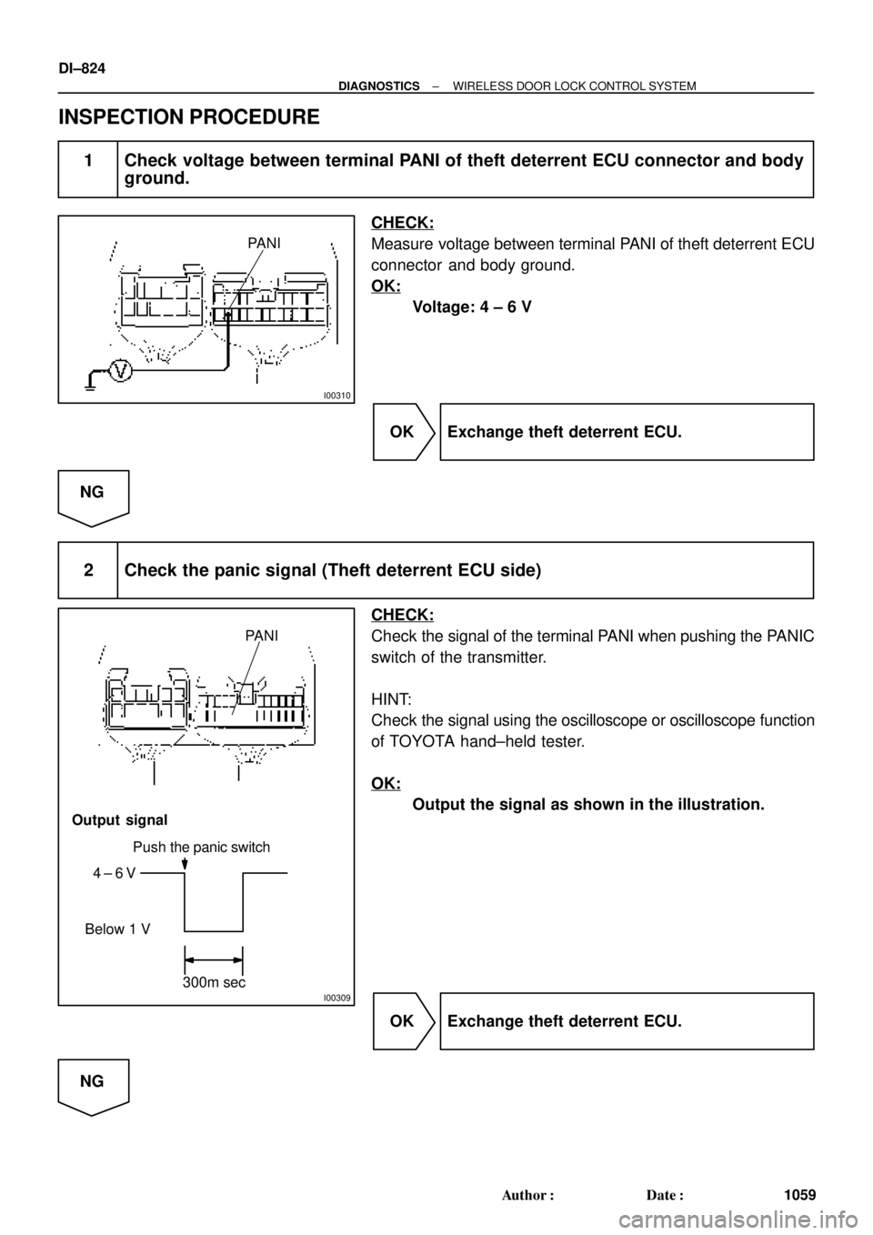
I00310
PANI
I00309
PANI
Push the panic switch
4 ± 6 V
Below 1 V
Output signal
300m sec
DI±824
± DIAGNOSTICSWIRELESS DOOR LOCK CONTROL SYSTEM
1059 Author�: Date�:
INSPECTION PROCEDURE
1 Check voltage between terminal PANI of theft deterrent ECU connector and body
ground.
CHECK:
Measure voltage between terminal PANI of theft deterrent ECU
connector and body ground.
OK:
Voltage: 4 ± 6 V
OK Exchange theft deterrent ECU.
NG
2 Check the panic signal (Theft deterrent ECU side)
CHECK:
Check the signal of the terminal PANI when pushing the PANIC
switch of the transmitter.
HINT:
Check the signal using the oscilloscope or oscilloscope function
of TOYOTA hand±held tester.
OK:
Output the signal as shown in the illustration.
OK Exchange theft deterrent ECU.
NG
Page 3245 of 4770
I00308
PANI
± DIAGNOSTICSWIRELESS DOOR LOCK CONTROL SYSTEM
DI±825
1060 Author�: Date�:
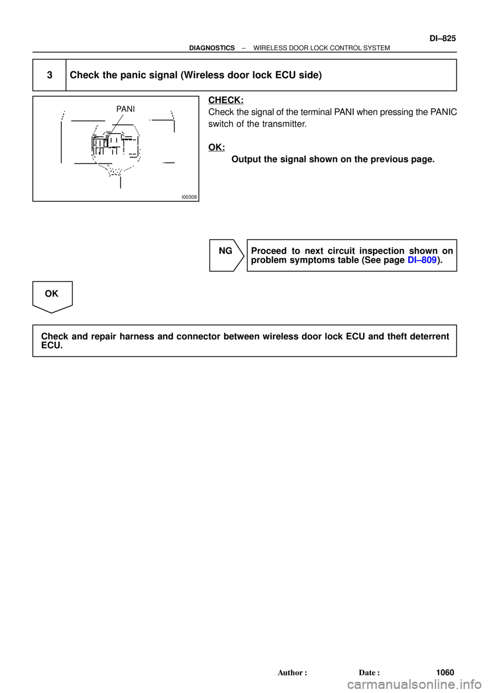
3 Check the panic signal (Wireless door lock ECU side)
CHECK:
Check the signal of the terminal PANI when pressing the PANIC
switch of the transmitter.
OK:
Output the signal shown on the previous page.
NG Proceed to next circuit inspection shown on
problem symptoms table (See page DI±809).
OK
Check and repair harness and connector between wireless door lock ECU and theft deterrent
ECU.
Page 3250 of 4770

I00229
0.75 ± 0.1 sec.
1.25 ± 0.1 sec.
ON
OFF
Blinking Pattern Security only: DI±830
± DIAGNOSTICSTHEFT DETERRENT SYSTEM
1065 Author�: Date�:
4. CANCELLATION OF THEFT DETERRENT OPERA-
TION OR MODE
The theft deterrent operation of mode can be cancelled when
any of the following conditions is met.
No.ConditionCancel of OperationCancel of Mode
1Unlock front doors with the keyEffectiveEffective
2Unlock doors with remote keyless entryEffectiveEffective
3Insert key into ignition key cylinder and turn
it to ACC or ON positionEffectiveEffective
4About 1 minute passes after theft deterrent
operation beginsAutomatic stop *1±
5Unlock the luggage compartment door with
the key or keyless entry.UneffectiveEffective
6Unlock the luggage compartment door with
the keyless entry.UneffectiveEffective
7
If the system receives panic signal again or
unlock signal when the system is activated
by panic signal
Effective *2Uneffective
6If the system receives unlock signal when
the system is activated by panic signalEffectiveEffective
*1: The system is set to the theft deterrent mode again in
about 2 seconds after the operation stops, if all doors are
closed.
*2: The alarm caused by the panic signal malces the sys-
tem in the previous condition.
5. INDICATOR LIGHT (LED)
The indicator light functions as shown below according to the
system condition in the theft deterrent mode. It remains OFF in
the initial state.
System ConditionIndicator Light
During set preparation timeON
When the mode is set*OFF
When alarm is activatedON
When the system is temporally cancelled*OFF
*: The indicator flashes with the output from the immobiliser.
6. KEEPING POWER SUPPLY FUNCTION IN CASE OF
DOME FUSE OPEN
Even if the dome fuse blows open on the theft deterrent mode,
the system will keep working on the theft deterrent mode.
Page 3252 of 4770
N09348
ECUTOYOTA hand±held tester
TOYOTA Break±out±box
DI±832
± DIAGNOSTICSTHEFT DETERRENT SYSTEM
1067 Author�: Date�:
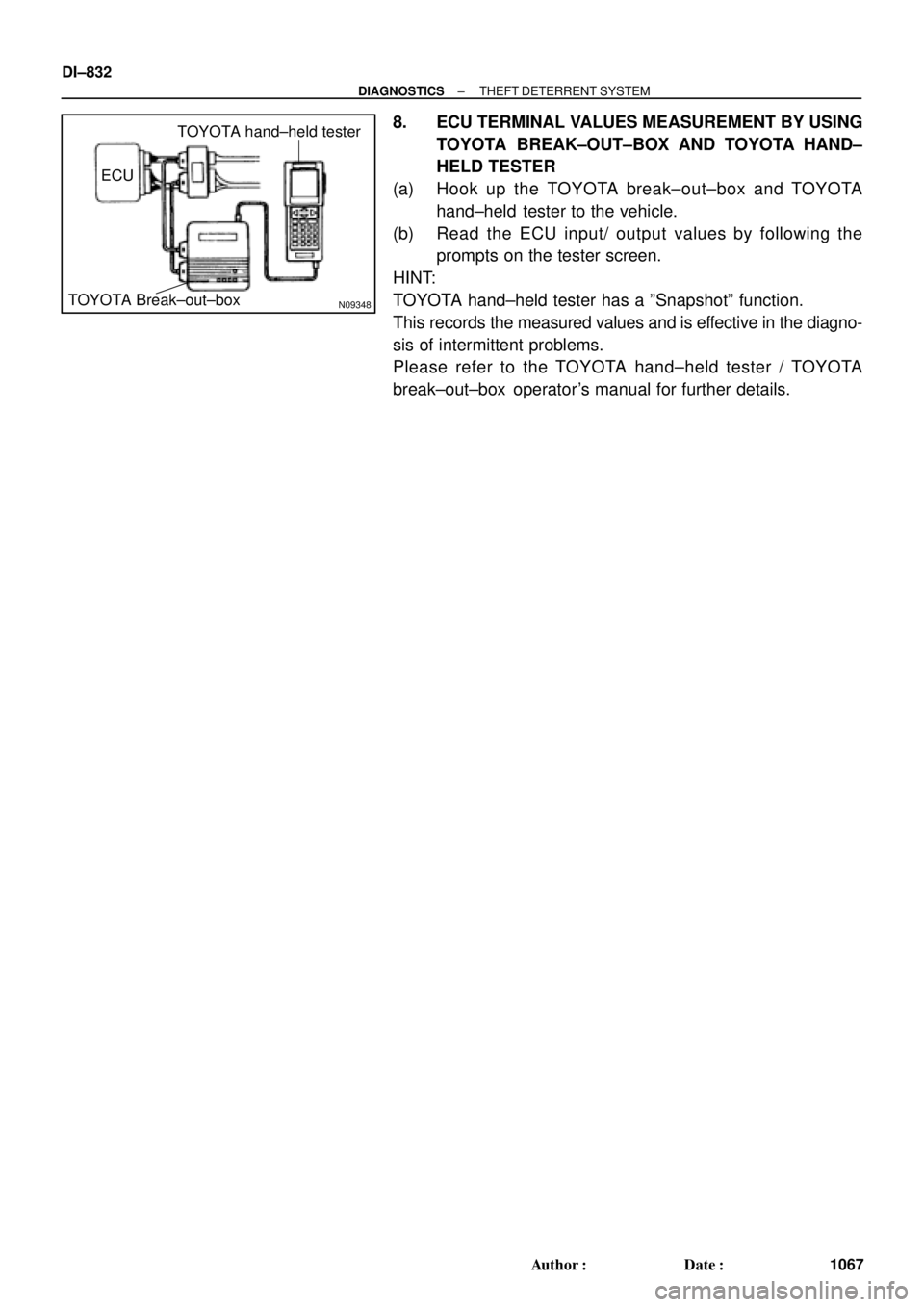
8. ECU TERMINAL VALUES MEASUREMENT BY USING
TOYOTA BREAK±OUT±BOX AND TOYOTA HAND±
HELD TESTER
(a) Hook up the TOYOTA break±out±box and TOYOTA
hand±held tester to the vehicle.
(b) Read the ECU input/ output values by following the
prompts on the tester screen.
HINT:
TOYOTA hand±held tester has a ºSnapshotº function.
This records the measured values and is effective in the diagno-
sis of intermittent problems.
Please refer to the TOYOTA hand±held tester / TOYOTA
break±out±box operator's manual for further details.