Page 3309 of 4770
Input SignalIndicator Light
Blinking Pattern
Drive at about
40 km/h (25 mph)
or below
Drive at about
40 km/h (25 mph)
or higherLightON
OFF
LightON
OFF
± DIAGNOSTICSCRUISE CONTROL SYSTEM
DI±889
1124 Author�: Date�:
INSPECTION PROCEDURE
1 Input signal check.
CHECK:
(a) See input signal check on page DI±870.
(b) Check indicator light operation when driving with vehicle
speed above 40 km/h (25 mph), and with vehicle speed
below 40 km/h (25 mph).
OK:
Vehicle speed above 40 km/h (25 mph):
Indicator light blinks
Vehicle speed below 40 km/h (25 mph):
Indicator light stays on
OK Check and replace cruise control ECU
(See page IN±31).
NG
2 Check speedometer circuit (See Combination meter troubleshooting on page
BE±2).
NG Repair or replace harness, connector or com-
bination meter assembly.
OK
3 Check harness and connector between cruise control ECU and combination me-
ter, combination meter and vehicle speed sensor (See page IN±31).
NG Repair or replace harness or connector.
OK
Page 3310 of 4770
DI±890
± DIAGNOSTICSCRUISE CONTROL SYSTEM
1125 Author�: Date�:
4 Check vehicle speed sensor (See page BE±47).
NG Replace vehicle speed sensor.
OK
Check and replace cruise control ECU
(See page IN±31).
Page 3311 of 4770
± DIAGNOSTICSCRUISE CONTROL SYSTEM
DI±891
1126 Author�: Date�:
DTC 23 Vehicle Speed Signal Abnormal
CIRCUIT DESCRIPTION
See page DI±888.
DTC No.Detection ItemTrouble Area
23Vehicle speed sensor pulse is abnormal.�Vehicle speed sensor
�Cruise control ECU
WIRING DIAGRAM
See page DI±888.
INSPECTION PROCEDURE
1 Check vehicle speed sensor (See page BE±47).
NG Replace vehicle speed sensor.
OK
Check and replace cruise control ECU
(See page IN±31).
DI08Q±10
Page 3312 of 4770
I00283
Cruise Control ECU
CMS
CCS
GND
CMS
W±L
W±B
W Cruise Control Switch
� Main Switch
� Control Switch
1J
78
W±B5
4
3
W±B MAIN
CANCEL
SET/COAST
RES/ACC
A11
10
16 CCS
EP
J7
J7J8 AJ/C
A
A
1J
W±B J/C
IGC15
C15
C15
J11
Instrument Panel J/B DI±892
± DIAGNOSTICSCRUISE CONTROL SYSTEM
1127 Author�: Date�:
DTC 32 Control Switch Circuit (Cruise Control
Switch)
CIRCUIT DESCRIPTION
This circuit carries the SET/COAST, RESUME/ACCEL and CANCEL signals (each voltage) to the ECU.
DTC No.Detection ItemTrouble Area
32Short in control switch circuit.
�Cruise control switch
�Harness or connector between cruise control ECU and
cruise control switch, cruise control switch and body ground
�Cruise control ECU
WIRING DIAGRAM
DI08R±12
Page 3313 of 4770
 (+)
± DIAGNOSTICSCRU")
Input SignalIndicator Light
Blinking Pattern
SET/COAST
switch
RESUME/ACCEL
switch
CANCEL switch2 Pulses
ON
OFF
ON
OFF3 Pulses
ON
OFFSW OFF
SW ON
AB0119
I00168
I00171
ON
CCS
(±) (+)
± DIAGNOSTICSCRUISE CONTROL SYSTEM
DI±893
1128 Author�: Date�:
INSPECTION PROCEDURE
1 Input signal check.
PREPARATION:
See input signal check on page DI±870.
CHECK:
Check the indicator light operation when each of the SET/
COAST, RESUME/ACCEL and CANCEL is turned on.
OK:
SET/COAST, RESUME/ACCEL switch
The signals shown in the table on the left should be
output when each switch is ON. The signal should
disappear when the switch is turned OFF.
CANCEL switch
The indicator light goes off when the cancel switch is
turned ON.
OK Wait and see.
NG
2 Check voltage between terminals CCS of cruise control ECU connector and body
ground.
PREPARATION:
(a) Remove the ECU with connector still connected.
(b) Turn ignition switch ON.
CHECK:
Measure voltage between terminals 18 of ECU connector and
body ground, when each of the SET/COAST, RESUME/AC-
CEL and CANCEL is turned ON.
Switch positionResistance (V)
Neutral10 ± 16 V
RES/ACC0.8 ± 3.7 V
SET/COAST2.5 ± 6.3 V
CANCEL4.2 ± 8.8 V
NG Proceed to next circuit inspection shown on
problem symptoms table (See page DI±879).
OK
Page 3314 of 4770
N16045
3 4
DI±894
± DIAGNOSTICSCRUISE CONTROL SYSTEM
1129 Author�: Date�:
3 Check control switch.
PREPARATION:
(a) Remove steering wheel center pad.
(b) Disconnect the control switch connector.
CHECK:
Measure resistance between terminals 3 and 4 of control switch
connector when control switch is operated.
Switch positionResistance (W)
Neutral8 (No continuity)
RES/ACC50 ± 80
SET/COAST180 ± 220
CANCEL400 ± 440
NG Replace control switch.
OK
4Check harness and connector between cruise control ECU and cruise control switch,
cruise control switch and body ground (See page
IN±31).
NG Repair or replace harness or connector.
OK
5 Input signal check (See step 1).
OK Wait and see.
NG
Check and replace cruise control ECU
(See page IN±31).
Page 3315 of 4770
I00284
Cruise Control ECU
IDL 13
L±R *
2*1
ECM
IDL
*
1: 5S±FE Engine
*2: 1MZ±FE Engine E7 E8
C15
34
± DIAGNOSTICSCRUISE CONTROL SYSTEM
DI±895
1130 Author�: Date�:
DTC 51 Idle Signal Circuit
CIRCUIT DESCRIPTION
When the idle switch is turned ON, a signal is sent to the ECU. The ECU uses this signal to correct the dis-
crepancy between the throttle valve position and the actuator position sensor value to enable accurate
cruise control at the set speed. If the idle switch is malfunctioning, problem symptoms also occur in the en-
gine, so also inspect the engine.
DTC No.Detection ItemTrouble Area
51Short in idle signal circuit.
�Harness or connector between ECM and throttle position
sensor
�Throttle position sensor
�Harness or connector between cruise control ECU and ECM
�Cruise control ECU
WIRING DIAGRAM
DI08S±10
Page 3316 of 4770
AB0119
I00167
I00172
ON
IDL
(±) (+)
DI±896
± DIAGNOSTICSCRUISE CONTROL SYSTEM
1131 Author�: Date�:
INSPECTION PROCEDURE
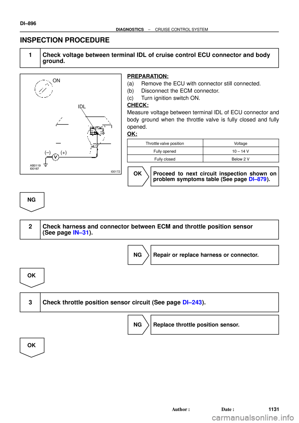
1 Check voltage between terminal IDL of cruise control ECU connector and body
ground.
PREPARATION:
(a) Remove the ECU with connector still connected.
(b) Disconnect the ECM connector.
(c) Turn ignition switch ON.
CHECK:
Measure voltage between terminal IDL of ECU connector and
body ground when the throttle valve is fully closed and fully
opened.
OK:
Throttle valve positionVoltage
Fully opened10 ± 14 V
Fully closedBelow 2 V
OK Proceed to next circuit inspection shown on
problem symptoms table (See page DI±879).
NG
2 Check harness and connector between ECM and throttle position sensor
(See page IN±31).
NG Repair or replace harness or connector.
OK
3 Check throttle position sensor circuit (See page DI±243).
NG Replace throttle position sensor.
OK

or below
Drive at about
40 km/h (25 mph)
or higherLightON
OFF
LightON
OFF
± DIAGNOSTICSCRUISE CONTROL SYSTEM
DI±889
112")